power outlet MERCEDES-BENZ GL450 2010 X164 Owner's Manual
[x] Cancel search | Manufacturer: MERCEDES-BENZ, Model Year: 2010, Model line: GL450, Model: MERCEDES-BENZ GL450 2010 X164Pages: 380, PDF Size: 9.81 MB
Page 10 of 380
Through standing water .................262
With Distronic ................................ 153
Driving and parking
Safety notes .................................. 108
Driving off .................................. 110, 261
Driving safety systems ....................... 61
4-ETS ............................................... 64
ABS .................................................. 62
BAS .................................................. 63
EBP .................................................. 63
ESP ®
................................................ 63
Driving systems
Air suspension program .................159
All-wheel drive (4MATIC) ................ 166
Cruise control ................................ 144
Distronic ........................................ 147
Downhill Speed Regulation (DSR) ..155
Hill-start assist system ..................155
Off-road driving program ...............158
Parktronic system ..........................166
Rear view camera .......................... 169
Driving tips, automatic
transmission ...................................... 117
DSR (Downhill Speed Regulation) .... 155
Messages in the multifunction
display ........................................... 303
E
Easy-entry/exit feature .............. 92, 139
EBP (Electronic Brake
Proportioning) ...................................... 63
Electrical system
Improper work on or
modifications ................................... 23
Power outlets ................................. 212
Electrical system (Technical data)
see Vehicle specification
Electronic Stability Program
see ESP ®
Electronic Traction System
see 4-ETS
Emergency, in case of
First aid kit ..................................... 284
Flat tire .......................................... 336
Hazard warning flasher ..................101
Roadside Assistance ................ 21, 216
Towing the vehicle .........................352
Emergency calls
Tele Aid .......................................... 215
Emergency engine shutdown ........... 357
Emergency operations
Limp-home mode ........................... 119
Remote door unlock (Tele Aid) .......219
Emergency Tensioning Device
see ETD
Emission control ............................... 272
Information label ............................ 361
System warranties ...........................20
Engine
Break-in recommendations ............226
Cleaning ......................................... 276
Compartment ................................ 228
Malfunction indicator
lamp ........................................ 29, 320
Messages in the multifunction
display ........................................... 306
Number .......................................... 361
Starting .......................................... 108
Turning off ..................................... 113
Engine (Technical data)
see Vehicle specification
Engine compartment
Radiator ......................................... 230
Engine coolant
see Coolant
Engine oil
Adding ........................................... 231
Additives ........................................ 371
Checking level ............................... 230
Consumption ................................. 230
Messages in the multifunction
display ........................................... 308
Oil dipstick ..................................... 230
Recommended engine oils and oil
filter ............................................... 370
ESP ®
(Electronic Stability
Program) .............................................. 63
4-ETS ............................................... 64
Messages in the multifunction
display ................................... 289, 300
Off-road ESP ®
.................................. 65
Trailer stabilization ........................... 65
Warning lamp ................................. 3188IndexX164_AKB; 5; 31, en-USd2ureepe,Version: 2.11.8.12009-09-11T12:30:16+02:00 - Seite 8
Page 16 of 380
Returning ....................................... 268
Ruts ............................................... 267
Steep terrain .................................. 264
Off-road driving program .................. 158
Off-road menu ................................... 131
Oil, oil level see Engine oil
On-board computer
see Control system
One-touch gearshifting ..................... 118
Operating safety .................................. 23
Ornamental moldings, cleaning ....... 277
Outside temperature see Displays
Overhead control panel ...................... 33
P
Paintwork, cleaning .......................... 276
Paintwork code ................................. 361
Panic alarm .......................................... 61
Panorama roof
Sunshade ....................................... 211
Parcel nets ......................................... 200
Parking ............................................... 112
Parktronic system ..........................166
Parking brake ............................ 112, 261
Messages in the multifunction
display ........................................... 300
Parking position
Exterior rear view mirrors ................95
Transmission position ....................116
Parktronic system
Cleaning system sensors ...............278
Malfunction .................................... 169
Minimum distance .........................167
Sensor range ................................. 167
Switching on/off ........................... 168
System sensors ............................. 167
Warning indicators ...................27, 168
Parts service ...................................... 360
PASS AIR BAG OFF indicator lamp
(Canada only) see Front passenger front air bag
off indicator lamp (Canada only)
PASS AIR BAG OFF indicator lamp
(USA only) see Front passenger front air bag
off indicator lamp (USA only)
Passenger safety
see Occupant safety
Pedals ................................................. 259
Phone see Telephone
Plastic parts, cleaning ...................... 279
Power assistance .............................. 259
Power outlets .................................... 212
Power seats see Seats
Power tailgate
Closing ............................................. 76
Messages in the multifunction
display ........................................... 304
Opening ........................................... 76
Power tilt/sliding sunroof
Operation ....................................... 192
Synchronizing ................................ 194
Power washer .................................... 276
Power windows ................................. 105
Cleaning ......................................... 278
Door windows ................................ 106
Hinged quarter windows ................106
Operation ....................................... 105
Rear door window, override
switch .............................................. 60
Synchronizing ................................ 107
Practical hints ................................... 284
Preglow indicator lamp .............. 29, 109
PRE-SAFE ®
............................................ 52
Messages in the multifunction
display ........................................... 290
Problems
While driving .................................. 111
With vehicle ..................................... 23
With wipers .................................... 105
Product information ............................ 20
Production options weight ............... 256
Proximity key see Key, SmartKey
PSI (air pressure unit) ....................... 25614IndexX164_AKB; 5; 31, en-USd2ureepe,Version: 2.11.8.12009-09-11T12:30:16+02:00 - Seite 14
Page 29 of 380
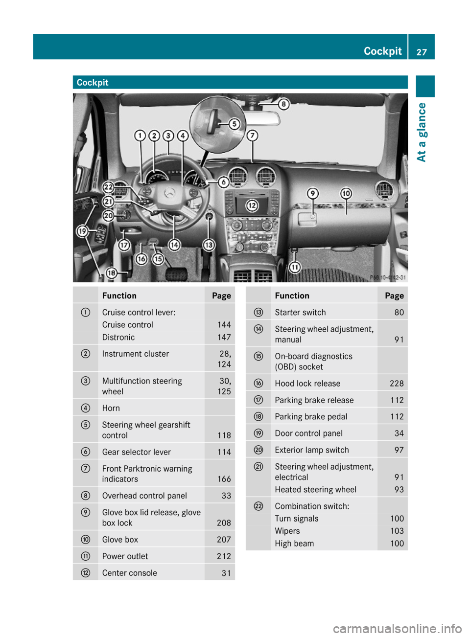
CockpitFunctionPage:Cruise control lever:Cruise control144Distronic147;Instrument cluster28,
124
=Multifunction steering
wheel
30,
125
?Horn ASteering wheel gearshift
control118
BGear selector lever114CFront Parktronic warning
indicators 166
DOverhead control panel33EGlove box lid release, glove
box lock208
FGlove box207GPower outlet212HCenter console31FunctionPageIStarter switch80JSteering wheel adjustment,
manual91
KOn-board diagnostics
(OBD) socket
LHood lock release228MParking brake release112NParking brake pedal112ODoor control panel34PExterior lamp switch97QSteering wheel adjustment,
electrical91
Heated steering wheel93RCombination switch:Turn signals100Wipers103High beam100Cockpit27At a glanceX164_AKB; 5; 31, en-USd2ureepe,Version: 2.11.8.12009-09-11T12:30:16+02:00 - Seite 27Z
Page 214 of 380
XReinstalling ashtray insert: Install
ashtray insert :.
XClosing: Push cover ;.
Cigarette lighter
GObserve Safety notes, see page 55.GWarning!
Never touch the heating element or sides of
the lighter; they are extremely hot. Hold the
knob only.
Make sure any children traveling with you do
not injure themselves or start a fire with the
hot cigarette lighter.
If the engine is off and the cigarette lighter is
being used extensively, the vehicle battery
may become discharged.
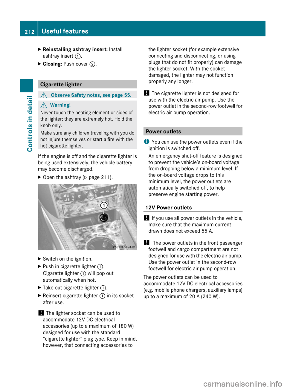
XOpen the ashtray (Y page 211).XSwitch on the ignition.XPush in cigarette lighter :.
Cigarette lighter : will pop out
automatically when hot.
XTake out cigarette lighter :.XReinsert cigarette lighter : in its socket
after use.
! The lighter socket can be used to
accommodate 12V DC electrical
accessories (up to a maximum of 180 W)
designed for use with the standard
“cigarette lighter” plug type. Keep in mind,
however, that connecting accessories to
the lighter socket (for example extensive
connecting and disconnecting, or using
plugs that do not fit properly) can damage
the lighter socket. With the socket
damaged, the lighter may not function
properly any longer.
! The cigarette lighter is not designed for
use with the electric air pump. Use the
power outlet in the second-row footwell for
electric air pump operation.
Power outlets
iYou can use the power outlets even if the
ignition is switched off.
An emergency shut-off feature is designed
to prevent the vehicle’s on-board voltage
from dropping below a minimum level. If
the on-board voltage drops to this
minimum level, the power outlets are
automatically switched off, to help
preserve engine starting power.
12V Power outlets
! If you use all power outlets in the vehicle,
make sure that the maximum current
drawn does not exceed 55 A.
! The power outlets in the front passenger
footwell and cargo compartment are not
designed for use with the electric air pump.
Use the power outlet in the second-row
footwell for electric air pump operation.
The power outlets can be used to
accommodate 12V DC electrical accessories
(e.g. mobile phone chargers, auxiliary lamps)
up to a maximum of 20 A (240 W).
212Useful featuresControls in detail
X164_AKB; 5; 31, en-USd2ureepe,Version: 2.11.8.12009-09-11T12:30:16+02:00 - Seite 212
Page 215 of 380
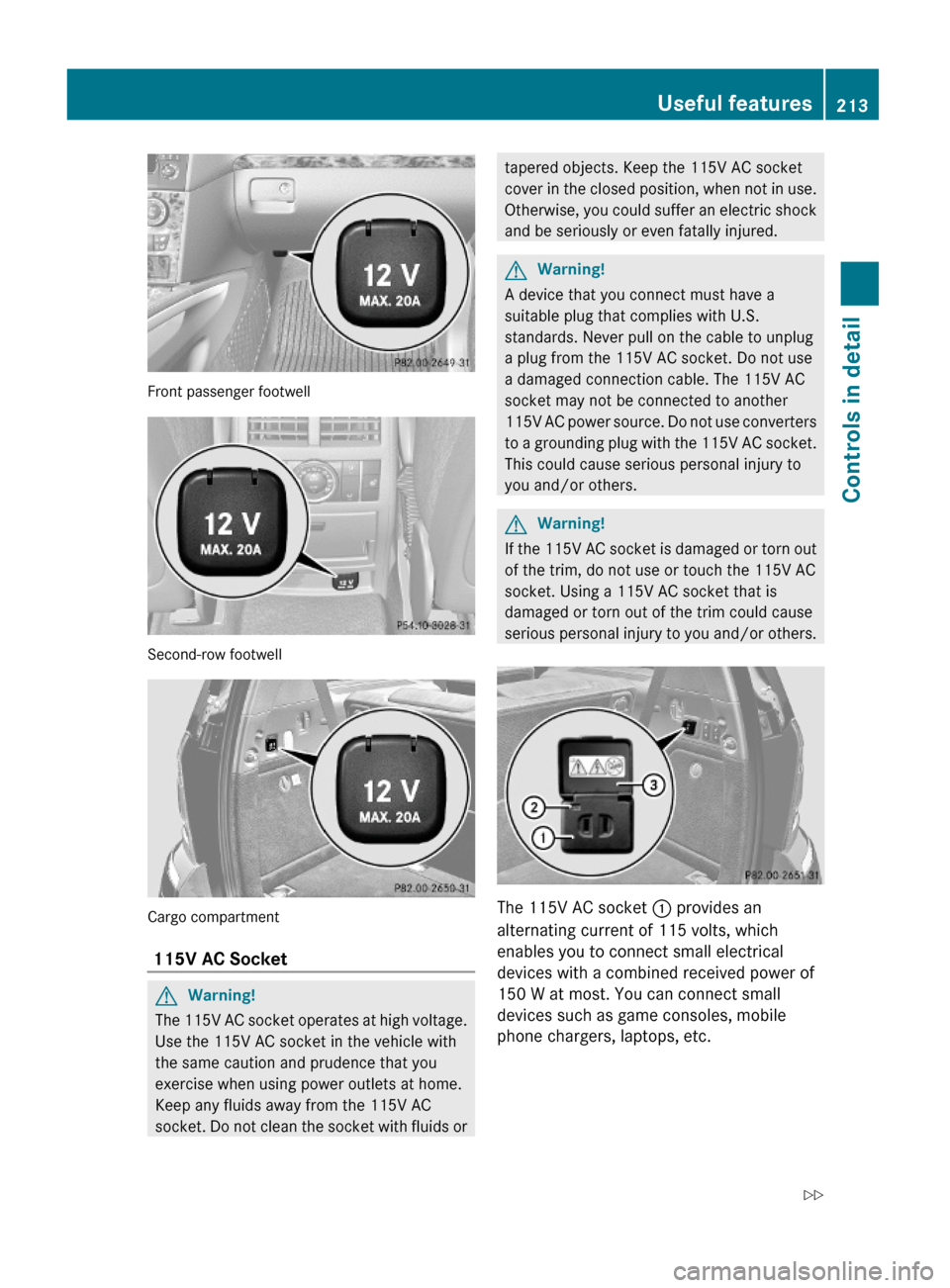
Front passenger footwell
Second-row footwell
Cargo compartment
115V AC Socket
GWarning!
The 115V AC socket operates at high voltage.
Use the 115V AC socket in the vehicle with
the same caution and prudence that you
exercise when using power outlets at home.
Keep any fluids away from the 115V AC
socket. Do not clean the socket with fluids or
tapered objects. Keep the 115V AC socket
cover in the closed position, when not in use.
Otherwise, you could suffer an electric shock
and be seriously or even fatally injured.
GWarning!
A device that you connect must have a
suitable plug that complies with U.S.
standards. Never pull on the cable to unplug
a plug from the 115V AC socket. Do not use
a damaged connection cable. The 115V AC
socket may not be connected to another
115V AC power source. Do not use converters
to a grounding plug with the 115V AC socket.
This could cause serious personal injury to
you and/or others.
GWarning!
If the 115V AC socket is damaged or torn out
of the trim, do not use or touch the 115V AC
socket. Using a 115V AC socket that is
damaged or torn out of the trim could cause
serious personal injury to you and/or others.
The 115V AC socket : provides an
alternating current of 115 volts, which
enables you to connect small electrical
devices with a combined received power of
150 W at most. You can connect small
devices such as game consoles, mobile
phone chargers, laptops, etc.
Useful features213Controls in detailX164_AKB; 5; 31, en-USd2ureepe,Version: 2.11.8.12009-09-11T12:30:16+02:00 - Seite 213Z
Page 216 of 380
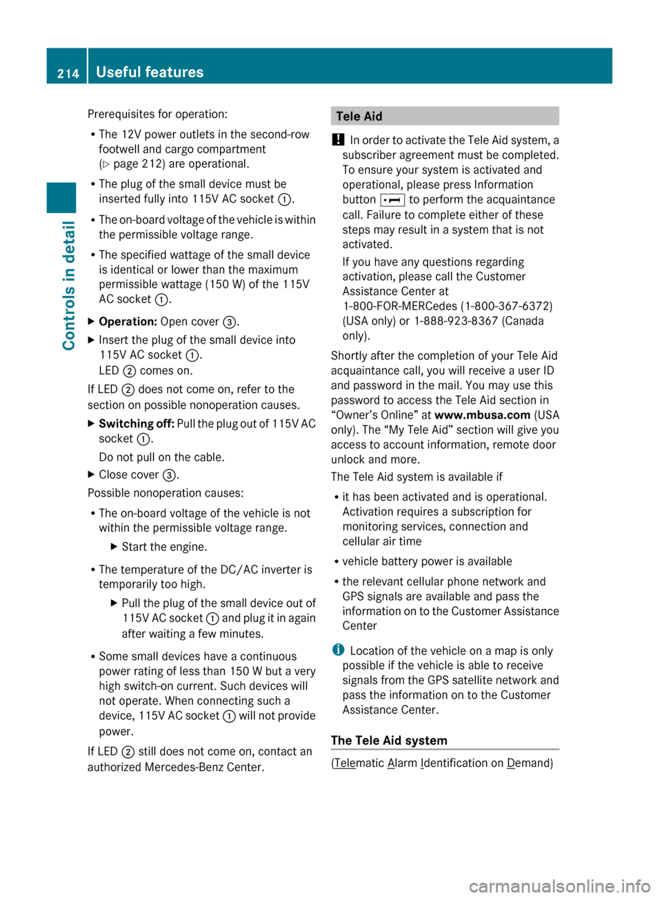
Prerequisites for operation:
R The 12V power outlets in the second-row
footwell and cargo compartment
( Y page 212) are operational.
R The plug of the small device must be
inserted fully into 115V AC socket :.
R The on-board voltage of the vehicle is within
the permissible voltage range.
R The specified wattage of the small device
is identical or lower than the maximum
permissible wattage (150 W) of the 115V
AC socket :.XOperation: Open cover =.XInsert the plug of the small device into
115V AC socket :.
LED ; comes on.
If LED
; does not come on, refer to the
section on possible nonoperation causes.
XSwitching off: Pull the plug out of 115V AC
socket :.
Do not pull on the cable.XClose cover =.
Possible nonoperation causes:
R The on-board voltage of the vehicle is not
within the permissible voltage range.
XStart the engine.
R The temperature of the DC/AC inverter is
temporarily too high.
XPull the plug of the small device out of
115V AC socket : and plug it in again
after waiting a few minutes.
R Some small devices have a continuous
power rating of less than 150 W but a very
high switch-on current. Such devices will
not operate. When connecting such a
device, 115V AC socket : will not provide
power.
If LED ; still does not come on, contact an
authorized Mercedes-Benz Center.
Tele Aid
! In order to activate the Tele Aid system, a
subscriber agreement must be completed.
To ensure your system is activated and
operational, please press Information
button E to perform the acquaintance
call. Failure to complete either of these
steps may result in a system that is not
activated.
If you have any questions regarding
activation, please call the Customer
Assistance Center at
1-800-FOR-MERCedes (1-800-367-6372)
(USA only) or 1-888-923-8367 (Canada
only).
Shortly after the completion of your Tele Aid
acquaintance call, you will receive a user ID
and password in the mail. You may use this
password to access the Tele Aid section in
“Owner’s Online” at www.mbusa.com (USA
only). The “My Tele Aid” section will give you
access to account information, remote door
unlock and more.
The Tele Aid system is available if
R it has been activated and is operational.
Activation requires a subscription for
monitoring services, connection and
cellular air time
R vehicle battery power is available
R the relevant cellular phone network and
GPS signals are available and pass the
information on to the Customer Assistance
Center
i Location of the vehicle on a map is only
possible if the vehicle is able to receive
signals from the GPS satellite network and
pass the information on to the Customer
Assistance Center.
The Tele Aid system
(Telematic Alarm Identification on Demand)
214Useful featuresControls in detail
X164_AKB; 5; 31, en-USd2ureepe,Version: 2.11.8.12009-09-11T12:30:16+02:00 - Seite 214
Page 339 of 380
Open doors only when conditions are safe
to do so.
XVehicles with KEYLESS-GO: Remove the
KEYLESS-GO start/stop button from the
starter switch.
XHave any passenger exit the vehicle at a
safe distance from the roadway. Open
doors only when conditions are safe to do
so.
iVehicles retrofitted with TIREFIT kit:
Only use the power outlet in the second-
row footwell for electric air pump
operation.
You can use the power outlet even when
the ignition is switched off, e.g. in order to
inflate the collapsible tire.
An emergency shut-off feature is designed
to prevent the vehicle’s on-board voltage
from dropping below a minimum level. If
the on-board voltage drops to this
minimum level, the power outlets are
switched off automatically to help preserve
engine starting power.
Sealing tires with TIREFIT
This section applies to vehicles retrofitted
with a TIREFIT kit only.
Small tire punctures, particularly those in the
tread, can be sealed with TIREFIT.
TIREFIT can be used in ambient temperatures
down to -4‡ (-20†).
GWarning!
TIREFIT is a limited repair device. TIREFIT
cannot be used for cuts or punctures larger
than approximately 0.16 in (4 mm) and tire
damage caused by driving with extremely low
tire inflation pressure, or on a flat tire, or a
damaged wheel.
Do not drive the vehicle under such
circumstances.
Contact the nearest authorized Mercedes-
Benz Center for assistance or call Roadside
Assistance.
XForeign objects (e.g. screws or nails)
should not be removed from the tire.
XTake the TIREFIT kit, the sticker, and the
electric air pump out of the vehicle.
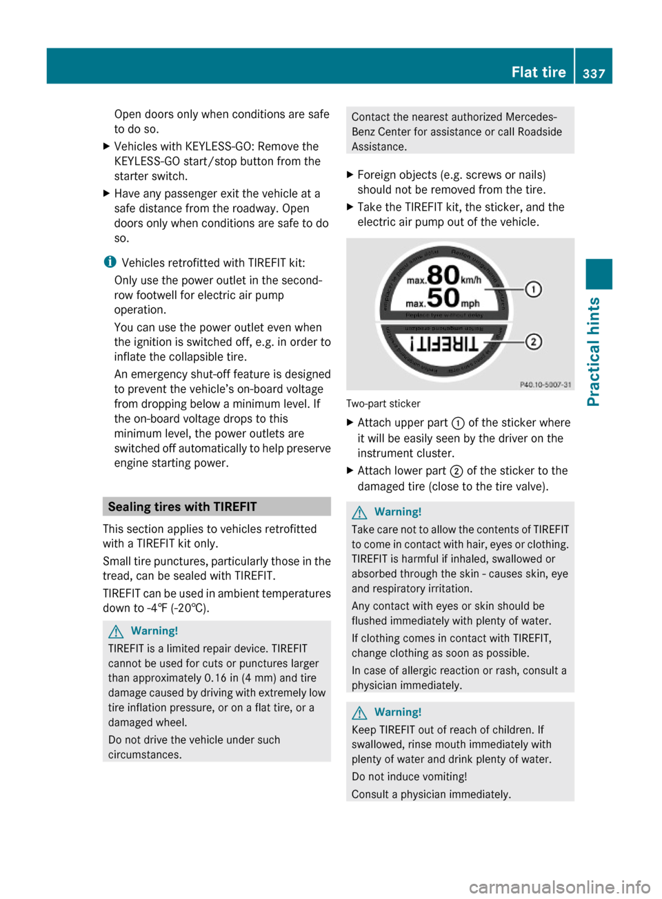
Two-part sticker
XAttach upper part : of the sticker where
it will be easily seen by the driver on the
instrument cluster.
XAttach lower part ; of the sticker to the
damaged tire (close to the tire valve).
GWarning!
Take care not to allow the contents of TIREFIT
to come in contact with hair, eyes or clothing.
TIREFIT is harmful if inhaled, swallowed or
absorbed through the skin - causes skin, eye
and respiratory irritation.
Any contact with eyes or skin should be
flushed immediately with plenty of water.
If clothing comes in contact with TIREFIT,
change clothing as soon as possible.
In case of allergic reaction or rash, consult a
physician immediately.
GWarning!
Keep TIREFIT out of reach of children. If
swallowed, rinse mouth immediately with
plenty of water and drink plenty of water.
Do not induce vomiting!
Consult a physician immediately.
Flat tire337Practical hintsX164_AKB; 5; 31, en-USd2ureepe,Version: 2.11.8.12009-09-11T12:30:16+02:00 - Seite 337Z
Page 340 of 380
iIf sealant has leaked out, let it dry. You
can then peel it off.
If clothing has come in contact with
TIREFIT, have it dry-cleaned with
perchloroethylene as soon as possible.
GWarning!
Observe safety instructions on air pump label.
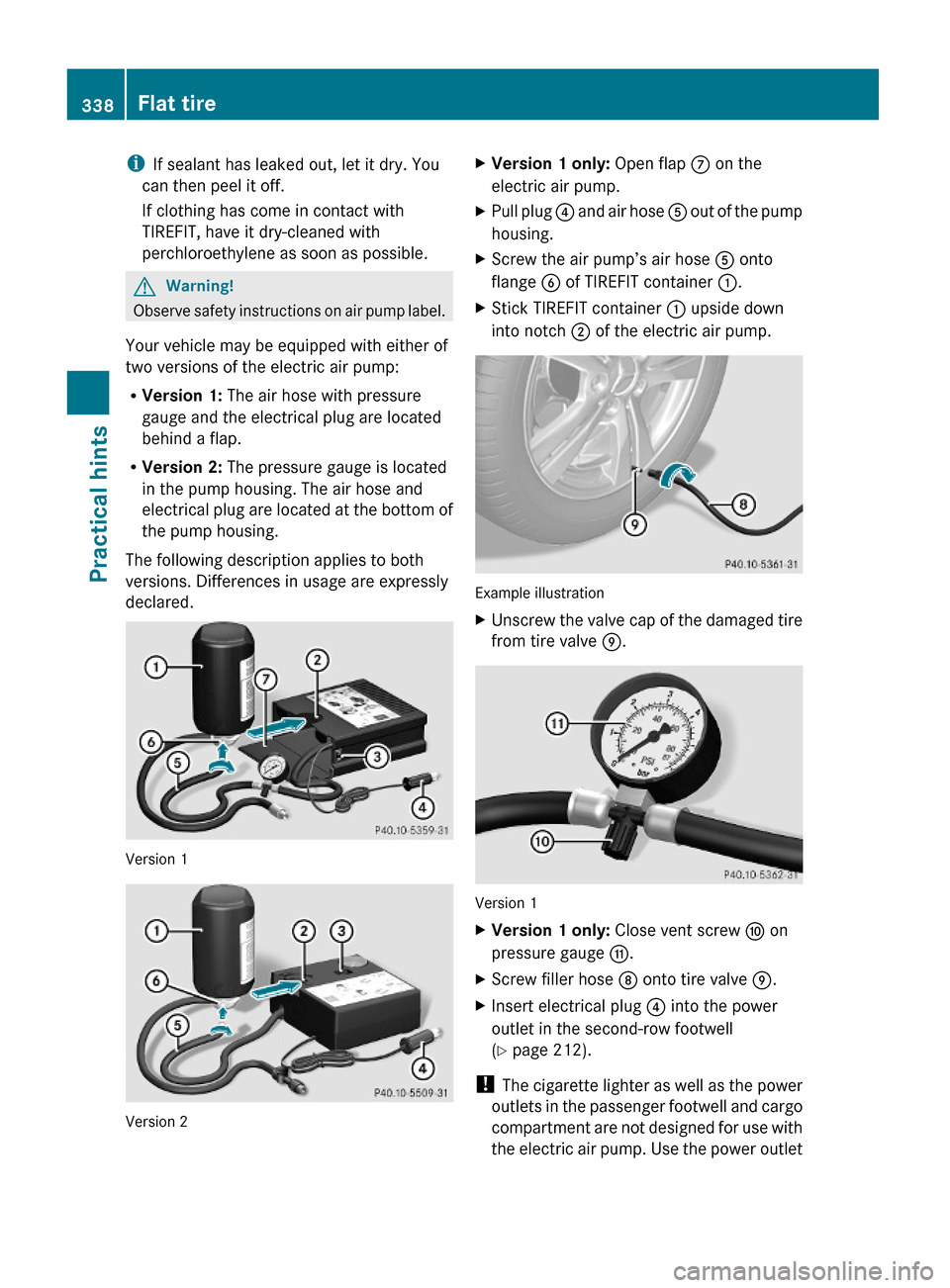
Your vehicle may be equipped with either of
two versions of the electric air pump:
RVersion 1: The air hose with pressure
gauge and the electrical plug are located
behind a flap.
RVersion 2: The pressure gauge is located
in the pump housing. The air hose and
electrical plug are located at the bottom of
the pump housing.
The following description applies to both
versions. Differences in usage are expressly
declared.
Version 1
Version 2
XVersion 1 only: Open flap C on the
electric air pump.
XPull plug ? and air hose A out of the pump
housing.
XScrew the air pump’s air hose A onto
flange B of TIREFIT container :.
XStick TIREFIT container : upside down
into notch ; of the electric air pump.
Example illustration
XUnscrew the valve cap of the damaged tire
from tire valve E.
Version 1
XVersion 1 only: Close vent screw F on
pressure gauge G.
XScrew filler hose D onto tire valve E.XInsert electrical plug ? into the power
outlet in the second-row footwell
(Y page 212).
! The cigarette lighter as well as the power
outlets in the passenger footwell and cargo
compartment are not designed for use with
the electric air pump. Use the power outlet
338Flat tirePractical hints
X164_AKB; 5; 31, en-USd2ureepe,Version: 2.11.8.12009-09-11T12:30:16+02:00 - Seite 338