technical data MERCEDES-BENZ GLC-Class 2016 X253 Owner's Manual
[x] Cancel search | Manufacturer: MERCEDES-BENZ, Model Year: 2016, Model line: GLC-Class, Model: MERCEDES-BENZ GLC-Class 2016 X253Pages: 418, PDF Size: 9.23 MB
Page 5 of 418
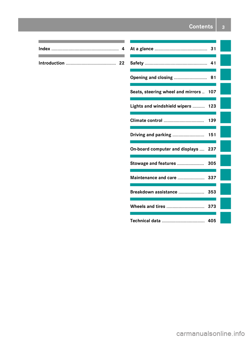
Index....................................................... 4
Introduction......................................... 22
At a glance........................................... 31
Safety................................................... 41
Opening and closing...........................81
Seats, steering wheel and mirrors ..107
Lights and windshield wipers ..........123
Climate control ................................. 139
Driving and parking..........................151
On-board computer and displays ....237
Stowage and features ......................305
Maintenance and care ......................337
Breakdown assistance .....................353
Wheels and tires ............................... 373
Technical data................................... 405
Contents3
Page 20 of 418
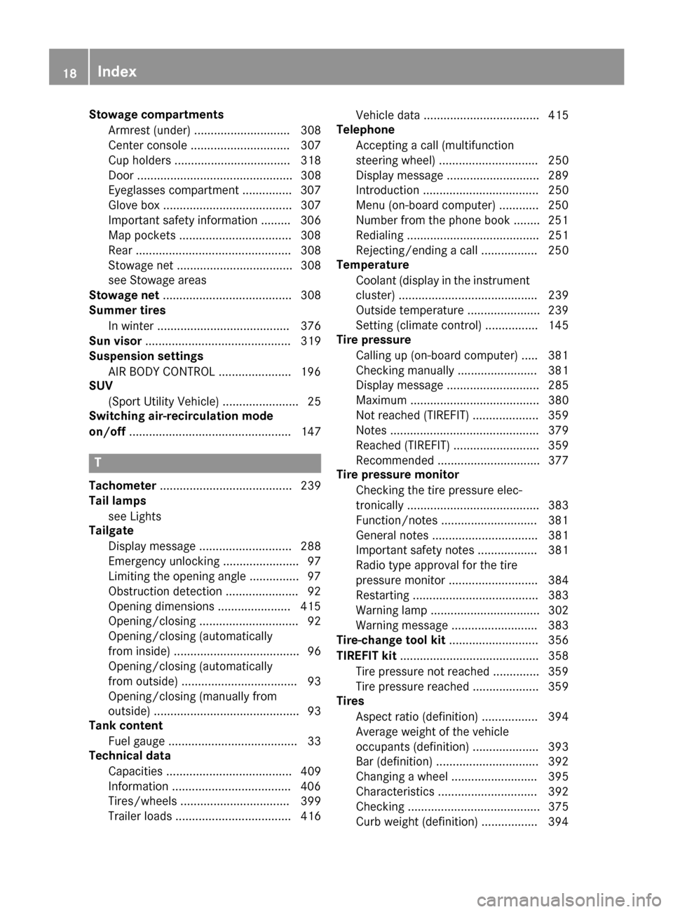
Stowage compartmentsArmrest (under) ............................. 308
Center console .............................. 307
Cup holders ................................... 318
Door ............................................... 308
Eyeglasses compartment ............... 307
Glove box ....................................... 307
Important safety information ......... 306
Map pockets ..................................3 08
Rear ............................................... 308
Stowage net ................................... 308
see Stowage areas
Stowage net ....................................... 308
Summer tires
In winter ........................................ 376
Sun visor ............................................ 319
Suspension settings
AIR BODY CONTROL ......................1 96
SUV
(Sport Utility Vehicle) ....................... 25
Switching air-recirculation mode
on/off ................................................. 147
T
Tachometer ........................................ 239
Tail lamps
see Lights
Tailgate
Display message ............................ 288
Emergency unlocking ....................... 97
Limiting the opening angle ...............9 7
Obstruction detection ......................9 2
Opening dimensions ......................4 15
Opening/closing .............................. 92
Opening/closing (automatically
from inside) ...................................... 96
Opening/closing (automatically
from outside) ................................... 93
Opening/closing (manually from
outside) ............................................ 93
Tank content
Fuel gauge ....................................... 33
Technical data
Capacities ...................................... 409
Information ....................................4 06
Tires/wheels ................................. 399
Trailer loads ................................... 416 Vehicle data ................................... 415
Telephone
Accepting a call (multifunction
steering wheel) .............................. 250
Display message ............................ 289
Introduction ................................... 250
Menu (on-board computer) ............ 250
Number from the phone book ........2 51
Redialing ........................................ 251
Rejecting/ending a call ................. 250
Temperature
Coolant (display in the instrument
cluster) .......................................... 239
Outside temperature ......................2 39
Setting (climate control) ................ 145
Tire pressure
Calling up (on-board computer) ..... 381
Checking manually ........................ 381
Display message ............................ 285
Maximum ....................................... 380
Not reached (TIREFIT) .................... 359
Notes ............................................. 379
Reached (TIREFIT) .......................... 359
Recommended ............................... 377
Tire pressure monitor
Checking the tire pressure elec-
tronically ........................................ 383
Function/notes .............................3 81
G
eneral notes ................................ 381
Important safety notes .................. 381
Radio type approval for the tire
pressure monitor ........................... 384
Restarting ...................................... 383
Warning lamp ................................. 302
Warning message .......................... 383
Tire-change tool kit ........................... 356
TIREFIT kit .......................................... 358
Tire pressure not reached .............. 359
Tire pressure reached .................... 359
Tires
Aspect ratio (definition) ................. 394
Average weight of the vehicle
occupants (definition) .................... 393
Bar (definition) ............................... 392
Changing a wheel .......................... 395
Characteristics .............................. 392
Checking ........................................ 375
Curb weight (definition) ................. 394
18Index
Page 29 of 418
the driver's footwell. Install the floormats
securely and as specified in order to ensure
sufficient clearance for the pedals. Do not use
loose floormats and do not place floormats on
top of one another.
!If the engine is switched off and equip-
ment on the diagnostics connection is
used, the starter battery may discharge.
Connecting equipment to the diagnostics
connection can lead to emissions monitoring
information being reset, for example. This
may lead to the vehicle failing to meet the
requirements of the next emissions test dur-
ing the main inspection.
Qualified specialist workshop
An authorized Mercedes-Benz Center is a
qualified specialist workshop. It has the nec-
essary specialist knowledge, tools and quali-
fications to correctly carry out the work
required on your vehicle. This is especially the
case for work relevant to safety.
Observe the notes in the Maintenance Book-
let.
Always have the following work carried out at an authorized Mercedes-Benz Center:
Rwork relevant to safety
Rservice and maintenance work
Rrepair work
Ralterations, installation work and modifica-
tions
Rwork on electronic components
Correct use
If you remove any warning stickers, you or
others could fail to recognize certain dangers.
Leave warning stickers in position.
Observe the following information when driv-
ing your vehicle:
Rthe safety notes in this manual
Rthe vehicle technical data
Rtraffic rules and regulations
Rlaws and safety standards pertaining to
motor vehicles
Problems with your vehicle
If you should experience a problem with your
vehicle, particularly one that you believe mayaffect its safe operation, we urge you to con-
tact an authorized Mercedes-Benz Center
immediately to have the problem diagnosed
and rectified. If the problem is not resolved to
your satisfaction, please discuss the problem
again with a Mercedes-Benz Center or con-
tact us at one of the following addresses.
In the USA
Customer Assistance Center
Mercedes-Benz USA, LLC
One Mercedes Drive
Montvale, NJ 07645-0350
In Canada
Customer Relations Department
Mercedes-Benz Canada, Inc.
98 Vanderhoof Avenue
Toronto, Ontario M4G 4C9
Reporting safety defects
USA only:
The following text is published as required ofmanufacturers under Title 49, Code of U.S.
Federal Regulations, Part 575 pursuant to the
"National Traffic and Motor Vehicle Safety Act
of 1966".
If you believe that your vehicle has a defect
which could cause a crash or could cause
injury or death, you should immediately
inform the National Highway Traffic Safety
Administration (NHTSA) in addition to notify-
ing Mercedes-Benz USA, LLC.
If NHTSA receives similar complaints, it may
open an investigation, and if it finds that a
safety defect exists in a group of vehicles, it
may order a recall and remedy campaign.
Introduction27
Z
Page 231 of 418
speed and do not countersteer. Apply the
brake as necessary.
Please observe the manufacturer's operating
instructions for the trailer coupling if a
detachable trailer coupling is used.
Couple and uncouple the trailer carefully. If
you do not couple the trailer to the towing
vehicle correctly, the trailer could become
detached.
Make sure that the following values are not
exceeded:
Rthe permissible trailer drawbar noseweight
Rthe permissible trailer load
Rthe permissible rear axle load of the towing
vehicle
Rthe maximum permissible gross vehicle
weight of both the towing vehicle and the
trailer
The applicable permissible values, which
must not be exceeded, can be found:
Rin the vehicle documents
Ron the identification plates of the trailer tow hitch, the trailer and the vehicle
If the values differ, the lowest value applies.
You will find the values approved by the man-
ufacturer on the vehicle identification plates
and those for the towing vehicle under "Tech-
nical data" (
Ypage 416).
When towing a trailer, your vehicle's handling
characteristics will be different in comparison
with when driving without a trailer.
The vehicle/trailer combination:
Ris heavier
Ris restricted in its acceleration and gradi-
ent-climbing capability
Rhas an increased braking distance
Ris affected more by strong crosswinds
Rdemands more sensitive steering
Rhas a larger turning radius
This could impair the handling characteris-
tics. When towing a trailer, always adjust your
speed to the current road and weather con-
ditions. Do not exceed the maximum permis-
sible speed for your vehicle/trailer combina-
tion.
General notes
RDo not exceed the legally prescribed max-
imum speed for vehicle/trailer combina-
tions in the relevant country.
This lowers the risk of an accident.
ROnly install an approved trailer coupling on
your vehicle.
Further information on availability and on
installation is available from any authorized Mercedes-Benz Center.
RThe bumpers of your vehicle are not suita-
ble for installing detachable trailer cou-
plings.
RDo not install hired trailer couplings or
other detachable trailer couplings on the
bumpers of your vehicle.
RTo reduce the risk of damage to the ball
coupling, remove it from the ball coupling
recess when not in use.
iWhen towing a trailer, set the tire pres-
sure on the rear axle of the towing vehicle
for a maximum load; see the tire pressure
table in the fuel filler flap (
Ypage 393).
Please note that when towing a trailer,
PARKTRONIC (
Ypage 198) is only available
with limitations or not at all.
iOn vehicles without level control, the
height of the ball coupling will alter accord-
ing to the load placed on the vehicle. If nec-
essary, use a trailer with a height-adjusta-
ble drawbar.
You will find installing dimensions and loads
under "Technical data" (
Ypage 415).
Driving tips
iObserve the notes on ESP®trailer stabi-
lization (
Ypage 75).
Towing a trailer229
Driving and parking
Z
Page 232 of 418
The maximum permissible speed for vehicle/
trailer combinations depends on the type of
trailer. Before beginning the journey, check
the trailer's documents to see what the max-
imum permissible speed is. Observe the
legally prescribed maximum speed in the rel-
evant country.
For certain Mercedes-Benz vehicles, the max-
imum permissible rear axle load is increased
when towing a trailer. Refer to the "Technical
data" section to find out whether this applies
to your vehicle.
If you utilize any of the added maximum rear
axle load when towing a trailer, the vehicle/
trailer combination may not exceed a maxi-
mum speed of 60 mph (100 km/h) for rea-
sons concerning the operating permit. This
also applies in countries in which the permis-
sible maximum speed for vehicle/trailer com-
binations is above 60 mph (100 km/h).
When towing a trailer, your vehicle's handling
characteristics will be different in comparison
with when driving without a trailer.
Use the left-hand steering wheel paddle
shifter to shift into a lower gear in good time
on long and steep downhill gradients.
iThis also applies if you have activated
cruise control.
This will use the braking effect of the engine,
so that less braking will be required to main-
tain the speed. This relieves the load on the
brake system and prevents the brakes from
overheating and wearing too quickly. If you
need additional braking, depress the brake
pedal repeatedly rather than continuously.
Driving tips
RMaintain a greater distance from the vehi-
cle in front than when driving without a
trailer.
RAvoid braking abruptly. If possible, brake
gently at first to allow the trailer to run on.
Then, increase the braking force rapidly.
RThe values given for gradient-climbing
capabilities from a standstill refer to sea level. When driving in mountainous areas,
note that the power output of the engine
and, consequently, the vehicle's gradient-
climbing capability, decreases with
increasing altitude.
If the trailer swings from side to side:
XDo not accelerate.
XDo not counter-steer.
XBrake if necessary.
Installing the ball coupling
GWARNING
If the ball coupling is not correctly installed
and secured, it can come loose during the
journey and endanger other road users. There is a risk of an accident and injury.
Always install and secure the ball coupling as
described. Before every journey, ensure that
the ball coupling is secured with the bolt and
the corresponding spring cotter.
GWARNING
If the ball coupling is not installed correctly or not secured with the bolt provided and the
corresponding spring cotter, the trailer may
come loose. There is a risk of an accident.
Always install and secure the ball coupling as
described. Before every journey, ensure that
the ball coupling is secured with the bolt and
the corresponding spring cotter.
GWARNING
If the ball coupling is not installed and secured
correctly the trailer may come loose. There is
a risk of an accident.
Install and secure the ball coupling as descri-
bed in the ball coupling installation instruc-
tions. Make sure that the ball coupling is
installed and secured correctly before every
journey.
230Towing a trailer
Driving and parking
Page 236 of 418
XMake sure that the automatic transmissionis set to position P.
XApply the vehicle's parking brake.
XClose all doors and the tailgate.
XApply the trailer's parking brake.
XRemove the trailer cable and decouple the
trailer.
Removing the ball coupling
XRemove the spring cotter.
XRemove the bolt from the ball coupling
recess.
XRemove the ball coupling from the ball cou-
pling recess.
XClean the ball coupling if it is dirty.
XStow the ball coupling so that it cannot be
thrown around.
Observe the loading guidelines (
Ypage 306)
and the safety notes regarding stowage
spaces (
Ypage 306).
Information on cleaning and care of the trailer
tow hitch (
Ypage 349).
Trailer power supply
The trailer socket of your vehicle is equipped
at the factory with a permanent power supply.
The permanent power supply is supplied via
trailer socket pin 4.
!Accessories with a maximum power con-
sumption of 180 W can be connected to the
permanent power supply.
You must not charge a trailer battery using
the power supply.
The trailer's permanent power supply is
switched off in the event of low vehicle supply
voltage and after six hours at the latest.
A qualified specialist workshop can provide
more information about installing the trailer
electrics.
Permissible trailer loads and trailer
drawbar noseweights
Weight specifications
The gross trailer weight is calculated by add-
ing the weight of the trailer to the weight of
the load and equipment on the trailer.
You will find installing dimensions and loads
under "Technical data" (
Ypage 415).
Loading a trailer
RWhen loading the trailer, make sure that
neither the permissible gross weight of the
trailer nor the gross vehicle weight is
exceeded. The permissible gross vehicle
weight is indicated on the identification
plate on the B-pillar on the driver's side of
the vehicle.
You can find the maximum permissible val-
ues on the type plates of your vehicle and
the trailer. When calculating how much
weight the vehicle and trailer may carry,
pay attention to the respective lowest val-
ues.
RThe trailer drawbar load on the ball coupling
must be added to the rear axle load to avoid
exceeding the permissible gross axle
weight. The permissible gross vehicle
weight is indicated on the identification
plate on the B-pillar on the driver's side of
the vehicle.
iMercedes-Benz recommends a trailer
load where the trailer drawbar noseweight
accounts for 8% to 15% of the trailer's per-
missible gross weight.
iThe weight of other accessories, passen-
gers and loads reduces:
Rthe permissible trailer load
Rthe permissible noseweight that your
vehicle can tow
234Towing a trailer
Driving and parking
Page 319 of 418
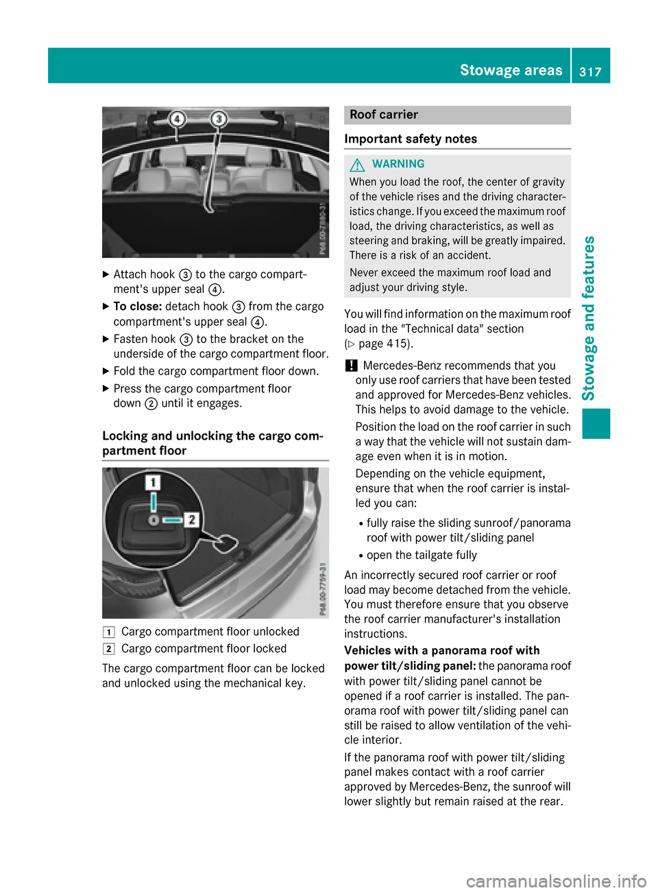
XAttach hook=to the cargo compart-
ment's upper seal ?.
XTo close:detach hook =from the cargo
compartment's upper seal ?.
XFasten hook=to the bracket on the
underside of the cargo compartment floor.
XFold the cargo compartment floor down.
XPress the cargo compartment floor
down ;until it engages.
Locking and unlocking the cargo com-
partment floor
1Cargo compartment floor unlocked
2Cargo compartment floor locked
The cargo compartment floor can be locked
and unlocked using the mechanical key.
Roof carrier
Important safety notes
GWARNING
When you load the roof, the center of gravity
of the vehicle rises and the driving character-
istics change. If you exceed the maximum roof
load, the driving characteristics, as well as
steering and braking, will be greatly impaired.
There is a risk of an accident.
Never exceed the maximum roof load and
adjust your driving style.
You will find information on the maximum roof
load in the "Technical data" section
(
Ypage 415).
!Mercedes-Benz recommends that you
only use roof carriers that have been tested
and approved for Mercedes-Benz vehicles.
This helps to avoid damage to the vehicle.
Position the load on the roof carrier in such
a way that the vehicle will not sustain dam-
age even when it is in motion.
Depending on the vehicle equipment,
ensure that when the roof carrier is instal-
led you can:
Rfully raise the sliding sunroof/panorama
roof with power tilt/sliding panel
Ropen the tailgate fully
An incorrectly secured roof carrier or roof
load may become detached from the vehicle.
You must therefore ensure that you observe
the roof carrier manufacturer's installation
instructions.
Vehicles with a panorama roof with
po
wer tilt/sliding panel: the panorama roof
with power tilt/sliding panel cannot be
opened if a roof carrier is installed. The pan-
orama roof with power tilt/sliding panel can
still be raised to allow ventilation of the vehi-
cle interior.
If the panorama roof with power tilt/sliding
panel makes contact with a roof carrier
approved by Mercedes-Benz, the sunroof will
lower slightly but remain raised at the rear.
Stowage areas317
Stowag ean d features
Z
Page 407 of 418
Useful information............................406
Information regarding technical
data .................................................... 406
Vehicle electronics ...........................406
Identification plates .........................408
Service products and filling capaci-
ties ..................................................... 409
Vehicle data ....................................... 415
Trailer tow hitch ................................ 415
405
Technical data
Page 408 of 418
Useful information
i
This Operator's Manual describes all
models and all standard and optional equip-
ment of your vehicle available at the time of
publication of the Operator's Manual.
Country-specific differences are possible.
Please note that your vehicle may not be
equipped with all features described. This
also applies to safety-related systems and
functions.
iRead the information on qualified special-
ist workshops (
Ypage 27).
Information regarding technical data
i
The data stated here specifically refers to
a vehicle with standard equipment. Consult an authorized Mercedes-Benz Center for
the data for all vehicle variants and trim
levels.
Vehicle electronics
Retrofitting two-way radios and
mobile phones (RF transmitters)
GWARNING
The electromagnetic radiation from modified
or incorrectly retrofitted RF-transmitters can
interfere with the vehicle electronics. This can compromise the operational safety of the
vehicle. There is a risk of an accident.
You should have all work to electrical and
electronic equipment carried out at a qualified
specialist workshop.
GWARNING
The electromagnetic radiation from incor-
rectly operated RF transmitters can interfere
with the vehicle electronics, for example:
Rif the RF transmitter is not connected with
an exterior antenna
Rthe exterior antenna has been installed
incorrectly or is not a low-reflection type
This can compromise the operational safety
of the vehicle. There is a risk of an accident.
Have the low-reflection exterior antenna
mounted at a qualified specialist workshop.
When operating RF transmitters in the vehi-
cle, always connect them with the low-reflec-
tion exterior antenna.
!The operating permit may be invalidated if
the instructions for installation and use of
RF transmitters are not observed.
In particular, the following conditions must
be complied with:
Ronly approved wavebands may be used.
Rcompliance with the maximum permissi-
ble output in these wavebands is
required.
Ronly approved antenna positions may be used.
Excessive levels of electromagnetic radiation
may cause damage to your health and the
health of others. Using an exterior antenna
takes into account current scientific discus-
sions relating to the possible health hazards
that may result from electromagnetic fields.
406Vehicle electronics
Technical data
Page 409 of 418
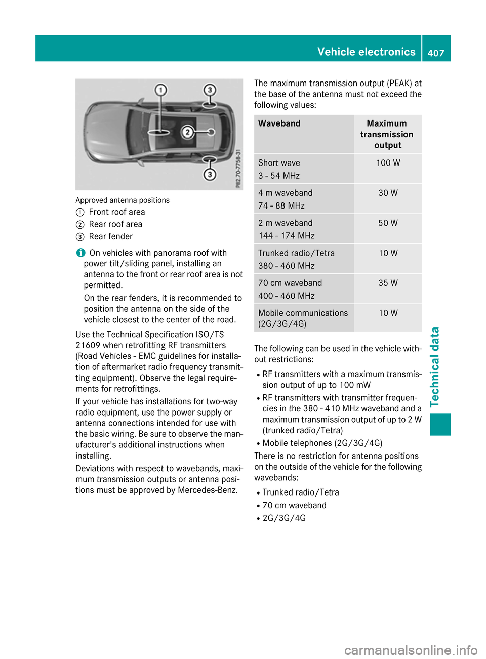
Approved antenna positions
:
Front roof area
;Rear roof area
=Rear fender
iOn vehicles with panorama roof with
power tilt/sliding panel, installing an
antenna to the front or rear roof area is not
permitted.
On the rear fenders, it is recommended to
position the antenna on the side of the
vehicle closest to the center of the road.
Use the Technical Specification ISO/TS
21609 when retrofitting RF transmitters
(Road Vehicles - EMC guidelines for installa-
tion of aftermarket radio frequency transmit-
ting equipment). Observe the legal require-
ments for retrofittings.
If your vehicle has installations for two-way
radio equipment, use the power supply or
antenna connections intended for use with
the basic wiring. Be sure to observe the man-
ufacturer's additional instructions when
installing.
Deviations with respect to wavebands, maxi-
mum transmission outputs or antenna posi-
tions must be approved by Mercedes-Benz. The maximum transmission output (PEAK) at
the base of the antenna must not exceed the
following values:
WavebandMaximum
transmission output
Short wave
3 - 54 MHz100 W
4 m waveband
74 - 88 MHz30 W
2 m waveband
144 - 174 MHz50 W
Trunked radio/Tetra
380 - 460 MHz10 W
70 cm waveband
400 - 460 MHz35 W
Mobile communications
(2G/3G/4G)10 W
The following can be used in the vehicle with-
out restrictions:
RRF transmitters with a maximum transmis-
sion output of up to 100 mW
RRF transmitters with transmitter frequen-
cies in the 380 - 410 MHz waveband and a
maximum transmission output of up to 2 W
(trunked radio/Tetra)
RMobile telephones (2G/3G/4G)
There is no restriction for antenna positions
on the outside of the vehicle for the following
wavebands:
RTrunked radio/Tetra
R70 cm waveband
R2G/3G/4G
Vehicle electronics407
Technical data
Z