lock MERCEDES-BENZ GLC COUPE 2016 User Guide
[x] Cancel search | Manufacturer: MERCEDES-BENZ, Model Year: 2016, Model line: GLC COUPE, Model: MERCEDES-BENZ GLC COUPE 2016Pages: 389, PDF Size: 7.34 MB
Page 26 of 389
Switching on/of
f........................... 117
TV
Operating (on-board computer) ..... 238
Two-way radio
Frequencies ................................... 371
Installation ..................................... 371
Transmission output (maximum) .... 371
Type identification plate
see Vehicle identification plate
Tyre changing tool kit ....................... 340
Tyre inflation compressor
see TIREFIT kit
Tyre pressure
Calling up (on-board computer) ..... 361
Display message ............................ 273
Not reached (TIREFIT) .................... 344
Reached (TIREFIT) .......................... 344
Recommended ............................... 359
Tyre pressure loss warning
General notes ................................ 360
Important safety notes .................. 361
Restarting ...................................... 361
Tyre pressure monitor
Checking the tyre pressure elec-
tronically ........................................ 362
Function/note s............................. 361
General notes ................................ 361
Important safety notes .................. 362
Radio type approval for the tyre
pressure monitor ........................... 364
Restarting ...................................... 363
Warning lamp ................................. 290
Warning message .......................... 363
Tyres
Changing a whee l.......................... 364
Checking ........................................ 356
Direction of rotation ...................... 365
Display message ............................ 273
Important safety notes .................. 356
Information on driving .................... 356
MOExtended tyre s......................... 358
Replacing ....................................... 364
Service life ..................................... 357
Snow chains .................................. 359
Storing ........................................... 365
Summer tyres in winter ................. 358
Tyre size (data ).............................. 368
Tyre tread ...................................... 357 Wheel and tyre combinations ........ 368
see Flat tyre U
Unlocking Emergency unlocking ....................... 90
From inside the vehicle (central
unlocking button) ............................. 89
USB devices
Connecting to the Media Inter-
face ............................................... 304
Using the TIREFIT
tyre pressure kit ............................ 343 V
Vanity mirror (in sun visor) .............. 317
Variable SPEEDTRONIC
see SPEEDTRONIC
Vehicle
Correct use ...................................... 30
Data acquisition ............................... 30
Display message ............................ 275
Electronics ..................................... 371
Equipment ....................................... 27
Implied warranty .............................. 30
Individual settings .......................... 240
Leaving parked up ......................... 170
Locking (in an emergency) ............... 90
Locking (key) ................................... 83
Lowering ........................................ 368
Operating safety .............................. 27
Parking .......................................... 167
Pulling away ................................... 146
Raising ........................................... 366
Registration ..................................... 30
Securing from rolling away ............ 365
Technical data ............................... 371
Towing away .................................. 350
Transporting .................................. 353
Unlocking (in an emergency) ........... 90
Unlocking (key) ................................ 83
Vehicle data ................................... 379
Vehicle dimensions ........................... 379
Vehicle emergency locking ................ 90
Vehicle identification number
see VIN Index
23
Page 32 of 389
documentation: director of the technical
department at Brano a.s.
4. Hradec nad Moravicí City
5. 05.05.2015 Date
Signed by
Director of Quality
TIREFIT kit Copy and translation of the original declaration of conformity:
EC declaration of conformity
In accordance with EC directive 2006/42/EC
We hereby declare that the product
Product designation: Daimler electric air pump
Model designation: 0851, DT/UW 200045
MB part no. :A 000 583 8000
complies with the following relevant regulations:
EMC 2004/108/EC (2014/30/EU)
Applied harmonised standards, in particular:
DIN EN 55014-1:2012-05
DIN EN 55014-2:2009-06
Manufacturer: Dunlop Tech GmbH
Address: Birkenhainerstrasse 77, 63450
Hanau, Germany
Authorised representative :I MS department
Date: March 2015
Signature: IMS-AM, IMS-AE-LDiagnostics connection
The diagnostics connection is used for connect- ing diagnostic equipment at a qualified special-
ist workshop. G
WARNING
If you connect equipment to a diagnostics
connection in the vehicle, it may affect the
operation of vehicle systems. As a result, the operating safety of the vehicle could be affec-
ted. There is a risk of an accident.
Only connect equipment to a diagnostics con-
nection in the vehicle, which is approved for
your vehicle by Mercedes-Benz. G
WARNING
Objects in the driver's footwell may restrict
the clearance around the pedals or block a
depressed pedal. This jeopardises the oper- ating and road safety of the vehicle. There is a
risk of an accident.
Stow all objects securely in the vehicle so that
they do not get into the driver's footwell.
Always fit the floormats securely and as pre-
scribed in order to ensure that there is always sufficient room for the pedals. Do not use
loose floormats and do not place several floor- mats on top of one another.
! If the engine is switched off and equipment
on the diagnostics connection is used, the
starter battery may discharge.
Connecting equipment to the diagnostics con-
nection can lead to emissions monitoring infor-
mation being reset, for example. This may lead
to the vehicle failing to meet the requirements of
the next emissions test during the main inspec- tion. Operating safety
29Introduction Z
Page 35 of 389
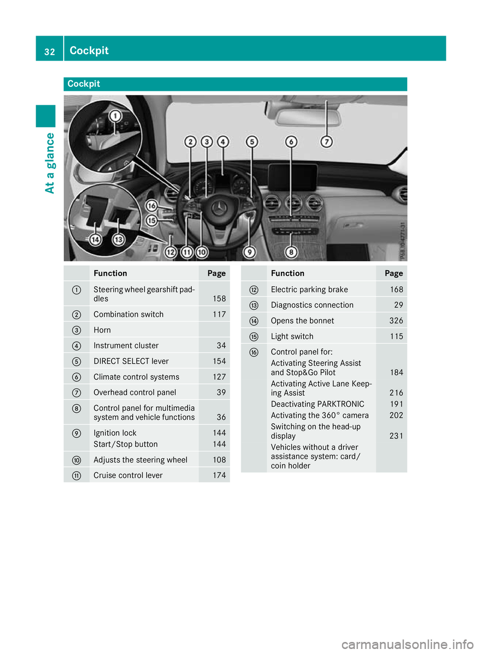
Cockpit
Function Page
:
Steering wheel gearshift pad-
dles 158
;
Combination switch 117
=
Horn
?
Instrument cluster 34
A
DIRECT SELECT lever 154
B
Climate control systems 127
C
Overhead control panel 39
D
Control panel for multimedia
system and vehicle functions
36
E
Ignition lock 144
Start/Stop button 144
F
Adjusts the steering wheel 108
G
Cruise control lever 174 Function Page
H
Electric parking brake 168
I
Diagnostics connection 29
J
Opens the bonnet 326
K
Light switch 115
L
Control panel for:
Activating Steering Assist
and Stop&Go Pilot 184
Activating Active Lane Keep-
ing Assist 216
Deactivating PARKTRONIC 191
Activating the 360° camera 202
Switching on the head-up
display
231
Vehicles without a driver
assistance system: card/
coin holder 32
CockpitAt a glance
Page 36 of 389
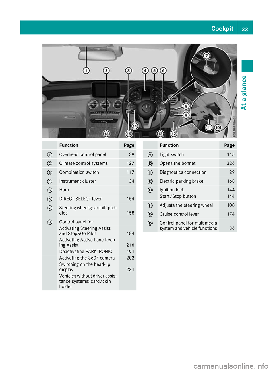
Function Page
:
Overhead control panel 39
;
Climate control systems 127
=
Combination switch 117
?
Instrument cluster 34
A
Horn
B
DIRECT SELECT lever 154
C
Steering wheel gearshift pad-
dles 158
D
Control panel for:
Activating Steering Assist
and Stop&Go Pilot
184
Activating Active Lane Keep-
ing Assist
216
Deactivating PARKTRONIC 191
Activating the 360° camera 202
Switching on the head-up
display
231
Vehicles without driver assis-
tance systems: card/coin
holder Function Page
E
Light switch 115
F
Opens the bonnet 326
G
Diagnostics connection 29
H
Electric parking brake 168
I
Ignition lock 144
Start/Stop button 144
J
Adjusts the steering wheel 108
K
Cruise control lever 174
L
Control panel for multimedia
system and vehicle functions
36Cockpit
33At a glance
Page 43 of 389
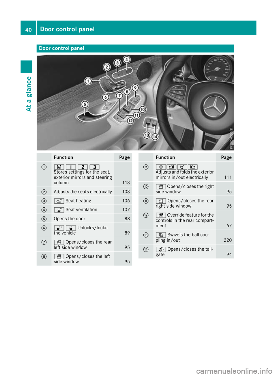
Door control panel
Function Page
:
r
45=
Stores settings for the seat,
exterior mirrors and steering
column 113
;
Adjusts the seats electrically 103
=
c
Seat heating 106
?
s
Seat ventilation 107
A
Opens the door 88
B
%&Unlocks/locks
the vehicle
89
C
W
Opens/closes the rear
left side window 95
D
W
Opens/closes the left
side window 95 Function Page
E
7Zª\
Adjusts and folds the exterior
mirrors in/out electrically 111
F
W
Opens/closes the right
side window 95
G
W
Opens/closes the rear
right side window 95
H
n
Override feature for the
controls in the rear compart-
ment 67
I
Ü
Swivels the ball cou-
pling in/out 220
J
p
Opens/closes the tail-
gate 9440
Door control panelAt a glance
Page 44 of 389
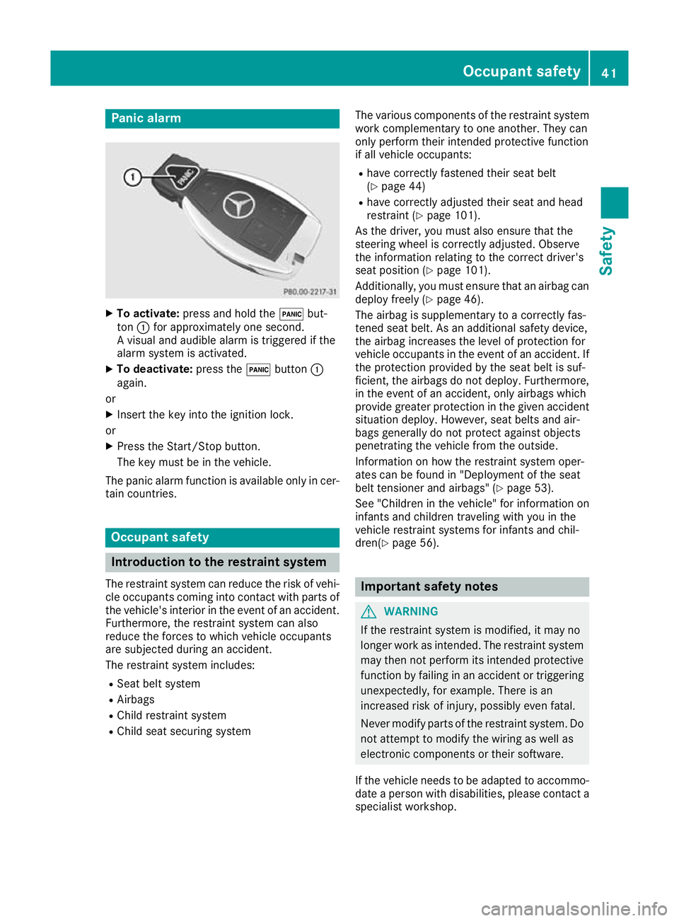
Panic alarm
X
To activate: press and hold the !but-
ton :for approximately one second.
A visual and audible alarm is triggered if the
alarm system is activated.
X To deactivate: press the!button :
again.
or X Insert the key into the ignition lock.
or X Press the Start/Stop button.
The key must be in the vehicle.
The panic alarm function is available only in cer- tain countries. Occupant safety
Introduction to the restraint system
The restraint system can reduce the risk of vehi- cle occupants coming into contact with parts of
the vehicle's interior in the event of an accident.
Furthermore, the restraint system can also
reduce the forces to which vehicle occupants
are subjected during an accident.
The restraint system includes:
R Seat belt system
R Airbags
R Child restraint system
R Child seat securing system The various components of the restraint system
work complementary to one another. They can
only perform their intended protective function
if all vehicle occupants:
R have correctly fastened their seat belt
(Y page 44)
R have correctly adjusted their seat and head
restraint (Y page 101).
As the driver, you must also ensure that the
steering wheel is correctly adjusted. Observe
the information relating to the correct driver's
seat position (Y page 101).
Additionally, you must ensure that an airbag can
deploy freely (Y page 46).
The airbag is supplementary to a correctly fas-
tened seat belt. As an additional safety device,
the airbag increases the level of protection for
vehicle occupants in the event of an accident. If the protection provided by the seat belt is suf-
ficient, the airbags do not deploy. Furthermore,
in the event of an accident, only airbags which
provide greater protection in the given accident situation deploy. However, seat belts and air-
bags generally do not protect against objects
penetrating the vehicle from the outside.
Information on how the restraint system oper-
ates can be found in "Deployment of the seat
belt tensioner and airbags" (Y page 53).
See "Children in the vehicle" for information on
infants and children traveling with you in the
vehicle restraint systems for infants and chil-
dren(Y page 56). Important safety notes
G
WARNING
If the restraint system is modified, it may no
longer work as intended. The restraint system
may then not perform its intended protective function by failing in an accident or triggering
unexpectedly, for example. There is an
increased risk of injury, possibly even fatal.
Never modify parts of the restraint system. Do not attempt to modify the wiring as well as
electronic components or their software.
If the vehicle needs to be adapted to accommo- date a person with disabilities, please contact a
specialist workshop. Occupant safety
41Safety Z
Page 46 of 389
tion system" (Y
page 49) and on "Children in
the vehicle" (Y page 56).
R All other persons: the PASSENGER AIR BAG
OFF indicator lamp must be off. The front-
passenger front airbag is enabled. Depending
on the stature of the person on the front-
passenger seat, the PASSENGER AIR BAG
OFF indicator lamp may light up. The front-
passenger front airbag is disabled. It will then
not be deployed in the event of an accident. In this case, the front-passenger seat should not
be used.
It is imperative to observe the notes on the
"Automatic front-passenger front airbag
deactivation system" (Y page 49) as well as
on "Seat belts" (Y page 43) and "Airbags"
(Y page 46). There, you can also find infor-
mation on the correct seat position. Seat belts
Introduction A correctly worn seat belt is the most effective
means of restraining the movement of vehicle
occupants in the event of a collision or if the
vehicle overturns. This reduces the risk of vehi-
cle occupants coming into contact with parts of
the vehicle interior or being ejected from it. The seat belt also helps to keep the vehicle occu-
pants in the best position in relation to the air-
bag being deployed.
The seat belt system consists of:
R seat belts
R belt tensioners for the front seat belts and the
outer seat belts in the rear
R belt force limiters for the front seat belts and
the outer seat belts in the rear
If the seat belt is pulled quickly or sharply from
the belt outlet, the inertia reel locks. The belt
strap cannot be pulled out any further.
The belt tensioner tightens the seat belt in the
event of a collision so that it fits tightly across
your body. However, it does not pull the vehicle
occupants back in the direction of the seat
backrest.
The belt tensioner does not, however, correct an
incorrect seat position or correct the routing of a seat belt that is worn incorrectly.
If the seat belt is also fitted with a belt force
limiter and this is triggered, the force exerted by
the seat belt on the vehicle occupant is reduced. The belt force limiters on the front seats are
synchronised with the front airbags, which take
on a part of the deceleration force. This can
reduce the forces to which the vehicle occu-
pants are subjected during an accident.
! If the co-driver's seat is not occupied, do not
engage the seat belt tongue in the buckle on
the co-driver's seat. Otherwise, the belt ten-
sioner could be triggered in the event of an
accident and would have to be replaced.
Important safety notes G
WARNING
If the seat belt is worn incorrectly, it cannot
perform its intended protective function. Fur- thermore, an incorrectly worn seat belt can
cause additional injuries, e.g. in the event of
an accident, heavy braking or sudden
changes of direction. There is an increased
risk of injury, possibly even fatal.
Always ensure that all vehicle occupants have their seat belts fastened correctly and are sit-
ting properly. G
WARNING
The seat belt does not offer the intended level of protection if you have not moved the back-
rest to an almost vertical position. When brak-
ing or in the event of an accident, you could
slide underneath the seat belt and sustain
abdomen or neck injuries, for example. This
poses an increased risk of injury or even fatal injury.
Adjust the seat properly before beginning
your journey. Always ensure that the backrest
is in an almost vertical position and that the
shoulder section of your seatbelt is routed
across the centre of your shoulder. G
WARNING
Persons under 1.50 mtall cannot wear the
seat belts correctly without an additional suit- able restraint system. If the seat belt is worn
incorrectly, it cannot perform its intended
protective function. Furthermore, an incor-
rectly worn seat belt can cause additional
injuries, e.g. in the event of an accident, heavy Occupant safety
43Safety
Z
Page 48 of 389
R
The seat belt is not routed over sharp, pointed
or fragile objects.
If such objects are located on or in your cloth- ing, e.g. pens, keys, spectacles, etc. stow
these in a suitable location.
R Only one person should use each seat belt at
any one time.
Babies and children must never travel sitting
on the lap of another vehicle occupant. In the event of an accident, they could be crushed
between the vehicle occupant and seat belt.
R Do not secure any objects with a seat belt if
the seat belt is being used by one of the vehi-
cle's occupants.
You must also make sure that objects, e.g.
cushions, are never placed between a person and the seat.
Seat belts are solely intended to secure and
restrain persons. To secure objects, luggage or
loads, always observe the "Loading guidelines"
(Y page 305).
Fastening and adjusting the seat belts Observe the safety notes on seat belts
(Y
page 43) and the information on correct use
of seat belts (Y page 44).
If a passenger is wearing the centre rear seat
belt, also observe the information on the seat
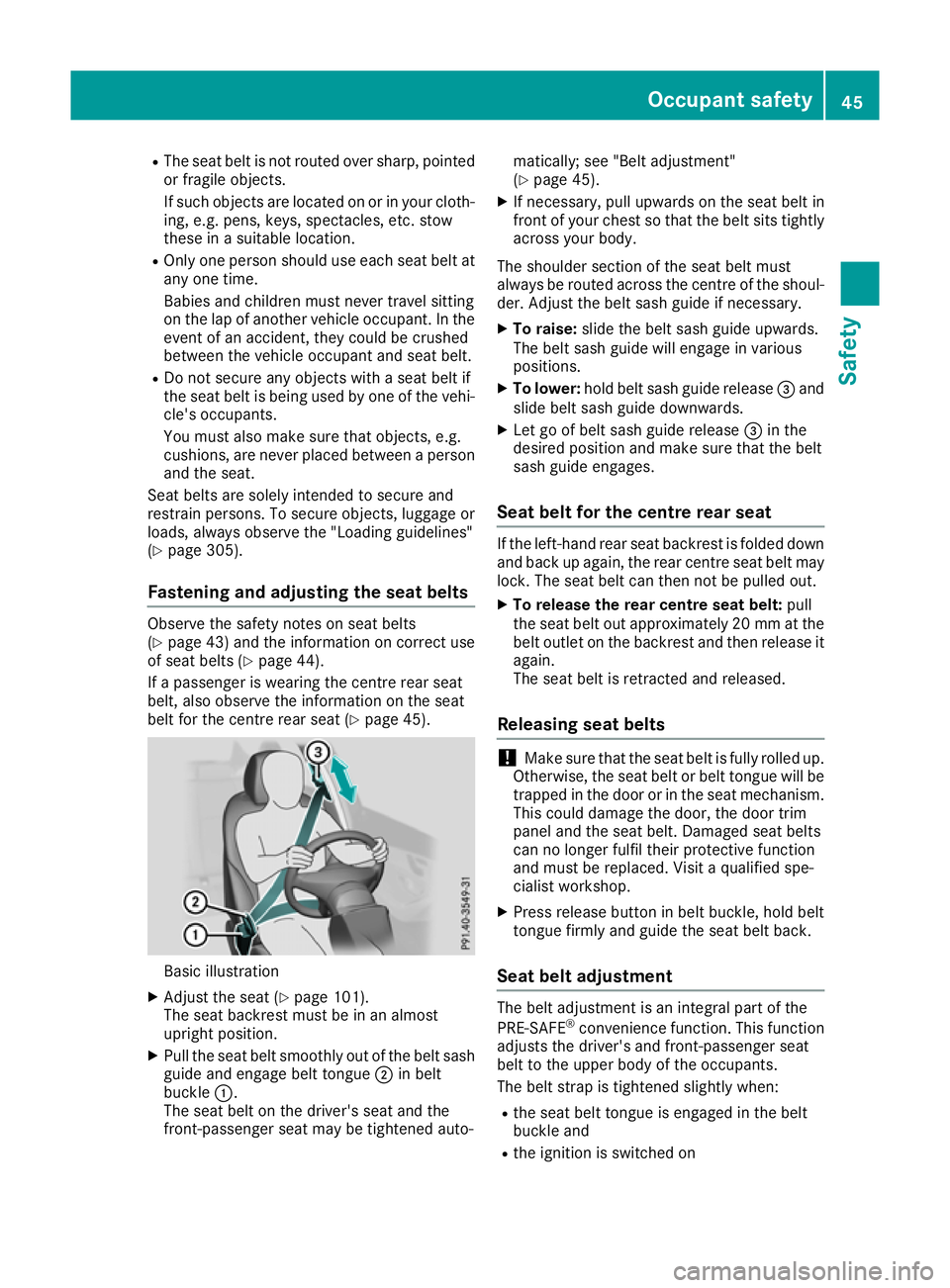
belt for the centre rear seat (Y page 45).Basic illustration
X Adjust the seat (Y page 101).
The seat backrest must be in an almost
upright position.
X Pull the seat belt smoothly out of the belt sash
guide and engage belt tongue ;in belt
buckle :.
The seat belt on the driver's seat and the
front-passenger seat may be tightened auto- matically; see "Belt adjustment"
(Y
page 45).
X If necessary, pull upwards on the seat belt in
front of your chest so that the belt sits tightly across your body.
The shoulder section of the seat belt must
always be routed across the centre of the shoul- der. Adjust the belt sash guide if necessary.
X To raise: slide the belt sash guide upwards.
The belt sash guide will engage in various
positions.
X To lower: hold belt sash guide release =and
slide belt sash guide downwards.
X Let go of belt sash guide release =in the
desired position and make sure that the belt
sash guide engages.
Seat belt for the centre rear seat If the left-hand rear seat backrest is folded down
and back up again, the rear centre seat belt may lock. The seat belt can then not be pulled out.
X To release the rear centre seat belt: pull
the seat belt out approximately 20 mm at the belt outlet on the backrest and then release itagain.
The seat belt is retracted and released.
Releasing seat belts !
Make sure that the seat belt is fully rolled up.
Otherwise, the seat belt or belt tongue will be
trapped in the door or in the seat mechanism. This could damage the door, the door trim
panel and the seat belt. Damaged seat belts
can no longer fulfil their protective function
and must be replaced. Visit a qualified spe-
cialist workshop.
X Press release button in belt buckle, hold belt
tongue firmly and guide the seat belt back.
Seat belt adjustment The belt adjustment is an integral part of the
PRE-SAFE ®
convenience function. This function
adjusts the driver's and front-passenger seat
belt to the upper body of the occupants.
The belt strap is tightened slightly when:
R the seat belt tongue is engaged in the belt
buckle and
R the ignition is switched on Occupant safety
45Safety Z
Page 52 of 389
Windowbags
:are integrated in the side of the
roof frame and deploy in the area from the A-
pillar to the C-pillar.
When deployed, the windowbag enhances the
level of protection for the head. However, it does
not protect the chest or arms.
In the event of a side impact, the windowbag is
deployed on the side on which an impact occurs.
If the system determines that it can offer addi-
tional protection to that provided by the seat
belt, a windowbag may be deployed in other
accident situations (Y page 53).Automatic front-passenger front air-
bag deactivation
Introduction In order to recognise a child restraint system on
the front-passenger seat, the automatic front-
passenger front airbag deactivation system cat- egorises the person in the front-passenger seat.Depending on that result, the front-passenger
front airbag is either enabled or disabled. If a
rearward-facing child restraint system is fitted
to the front-passenger seat, the PASSENGER
AIR BAG OFF indicator lamp must light up after
the system self-test and remain lit. The front-
passenger front airbag is disabled.
The system does not disable:
R the sidebag
R the windowbag
R the seat belt tensioner
Make sure that your vehicle is equipped with the automatic front-passenger front airbag deacti-
vation system (Y page 60). If this is not the
case, always install a child restraint system on a
suitable rear seat (Y page 61).
If it is absolutely necessary to install a child
restraint system on the front-passenger seat, be
sure to observe the correct positioning of the
child restraint system. Never place objects
under or behind the child restraint system, e.g. a
cushion. Fully retract the seat cushion length.
The entire base of the child restraint system
must always rest on the seat cushion of the
front-passenger seat. The backrest of a forward-
facing child restraint system must, as far as
possible, rest flat against the backrest of the
front-passenger seat. The child restraint system must not touch the roof or be put under strain bythe head restraint. Adjust the angle of the seat backrest and the head restraint position accord-
ingly. Only then is the correct function of the
automatic front-passenger front airbag deacti-
vation system guaranteed. Always observe the
information on suitable positioning of the child
restraint system (Y page 61) in addition to the
child restraint system manufacturer's installa-
tion instructions.
Operation of automatic front-passenger
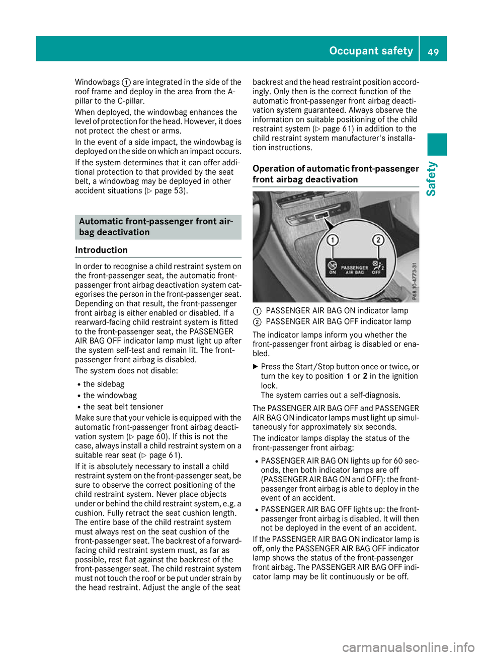
front airbag deactivation :
PASSENGER AIR BAG ON indicator lamp
; PASSENGER AIR BAG OFF indicator lamp
The indicator lamps inform you whether the
front-passenger front airbag is disabled or ena-
bled. X Press the Start/Stop button once or twice, or
turn the key to position 1or 2in the ignition
lock.
The system carries out a self-diagnosis.
The PASSENGER AIR BAG OFF and PASSENGER AIR BAG ON indicator lamps must light up simul-
taneously for approximately six seconds.
The indicator lamps display the status of the
front-passenger front airbag:
R PASSENGER AIR BAG ON lights up for 60 sec-
onds, then both indicator lamps are off
(PASSENGER AIR BAG ON and OFF): the front-
passenger front airbag is able to deploy in the event of an accident.
R PASSENGER AIR BAG OFF lights up: the front-
passenger front airbag is disabled. It will then
not be deployed in the event of an accident.
If the PASSENGER AIR BAG ON indicator lamp is off, only the PASSENGER AIR BAG OFF indicator
lamp shows the status of the front-passenger
front airbag. The PASSENGER AIR BAG OFF indi- cator lamp may be lit continuously or be off. Occupant safety
49Safety Z
Page 57 of 389
ticularly if a seat belt tensioner was triggered or
an airbag was deployed.
An electric motor is used by PRE-SAFE ®
to trig-
ger the tightening of the seat belt in hazardous
situations. This procedure is reversible.
If the belt tensioners are triggered or an airbag is
deployed, you will hear a bang, and a small
amount of powder may also be released. The
6 restraint system warning lamp lights up.
Only in rare cases will the bang affect your hear-
ing. In general, the powder released is not haz-
ardous to health but may cause short-term
breathing difficulties to persons suffering from
asthma or other pulmonary conditions. Provided it is safe to do so, you should leave the vehicle
immediately or open the window in order to pre- vent breathing difficulties.
Operation During the first stage of a collision, the restraint
system control unit evaluates important physi-
cal data relating to vehicle deceleration or accel-
eration, such as:
R duration
R direction
R intensity
Based on the evaluation of this data, the
restraint system control unit triggers the seat
belt tensioners in the event of a head-on or rear
collision.
A seat belt tensioner can be triggered only if:
R the ignition is switched on
R the components of the restraint system are
operational. You can find further information
under: "Restraint system warning lamp"
(Y page 42)
R the seat belt buckle tongue has engaged in
the belt buckle of the respective front seat
The seat belt tensioners in the rear compart-
ment are triggered independently of the lock
status of the seat belts.
If the restraint system control unit detects a
high-severity accident, in certain head-on colli-
sions, additional components of the restraint
system are deployed independently of each
other:
R Front airbags and driver's kneebag
R Windowbag, if the system determines that
deployment can offer additional protection to that provided by the seat belt On vehicles with the automatic front-passenger
front airbag deactivation system: depending on
the person in the front-passenger seat, the
front-passenger front airbag is either disabled or enabled. The front-passenger front airbag can
be deployed in an accident only if the
PASSENGER AIR BAG OFF indicator lamp is off.
Observe the information on the PASSENGER AIR BAG indicator lamps (Y page 42).
Your vehicle has two-stage front airbags. In the
first deployment stage, the front airbag is filled
with propellant gas to reduce the risk of injuries. The front airbag is fully deployed if the second
deployment stage is activated within a few mil-
liseconds.
The activation threshold for the seat belt ten-
sioners and airbags is determined based on the
evaluation of the vehicle's rate of deceleration
or acceleration at various points in the vehicle.
This process is pre-emptive in nature. The trig-
gering/deployment process should take place
in good time at the start of the collision.
The rate of vehicle deceleration or acceleration
and the direction of the force are essentially
determined by:
R the distribution of forces during the collision
R the collision angle
R the deformation characteristics of the vehicle
R the characteristics of the object with which
the vehicle has collided
Factors that can be seen and measured only
after a collision has occurred do not play a deci-
sive role in the deployment of an airbag, nor do
they provide an indication of airbag deployment.
The vehicle may be deformed significantly with-
out an airbag being deployed. This is the case if only parts that are relatively easily deformed are
affected and the rate of deceleration is not high. Conversely, an airbag may be deployed even
though the vehicle suffers only minor deforma-
tion. This is the case if, for example, very rigid
vehicle parts such as longitudinal body mem-
bers are hit, and sufficient deceleration occurs
as a result.
If the restraint system control unit detects a side
impact or if the vehicle overturns, the applicable components of the restraint system are activa-
ted independently of each other depending on
the apparent type of accident.
R Sidebags on the side of the impact, independ-
ent of the seat belt tensioner and seat belt
usage 54
Occupant safetySafety