charging MERCEDES-BENZ GLC COUPE 2021 Owners Manual
[x] Cancel search | Manufacturer: MERCEDES-BENZ, Model Year: 2021, Model line: GLC COUPE, Model: MERCEDES-BENZ GLC COUPE 2021Pages: 481, PDF Size: 9 MB
Page 5 of 481
Symbols
........................................................ 5At
agl ance .................................................... 6
Cockpit ........................................................... 6
Indica tor and warning lamps (s tandard) ........ 10
Indicator and warning lamps (widesc reen
cockpit) ......................................................... 12
Overhead contro l panel ................................ 14
Door operating unit and seat adjustment ..... 16
Emergencies and breakdowns ...................... 18Digital Owner's Manual
.............................20
Calling up the Digital Owner's Manual ..........20 Genera
l notes............................................. 22
Pr otection of the environment ......................22
Ta ke -ba ckof end-of-life vehicles ...................22
Mercedes-Benz GenuineParts ....................... 23
Owner's Manual ............................................ 24
Operating saf ety .......................................... .24
Declaration of conformity ............................. 26
Diagno stics connection ................................ 30
Qualified specialist workshop ....................... 31Ve
hicle registration ....................................... 32
Cor rect use of theve hicle ............................32
Information on the REA CHregulation ........... 32
No tesfo r persons with electronic medi‐
cal aids ......................................................... 33
Implied warranty .......................................... .33
QR code forre scue card ...............................33
Data storage .................................................34
Copyright ...................................................... 37 Occupant saf
ety......................................... 38
Re stra int sy stem ...........................................38
Seat belts ..................................................... 40
Airbags ......................................................... 44
PRE-SAFE ®
sy stem ....................................... 52
Safely transporting children in theve hi‐
cle ................................................................53
No tes on pets in theve hicle .........................72 Opening and closing
.................................. 73
Ke y .............................................................. .73
Doo rs............................................................ 76
Load compartment ....................................... 81
Side windo ws............................................... 86 Sliding sunroof ............................................. 89
Ro
ller sunblinds ............................................ 92
Anti-th eft protection .....................................93 Seats and
stowing ..................................... 96
No tes on the cor rect driver's seat posi‐
tion ............................................................... 96
Seats ............................................................ 97
St eering wheel ............................................ 104
Easy entry and exitfeature ........................ .106
Memory function ........................................ 107
St ow age areas ............................................ 108
Soc kets ....................................................... 121
Wi reless charging of the mobile phone
and connection with theex terior aerial ...... 12 3
Fitting/removing thefloor mats ................. 12 5 Light and sight
......................................... 127
Exterior lighting .......................................... 127
Interior lighting ........................................... 13 5
Wi ndsc reen wipers and windscreen
wa sher sy stem ............................................ 13 6
Mir rors ........................................................ 13 92
Contents
Page 34 of 481
&
WARNING Risk of accident due to
objects in the driver's foot we ll
Objects in the driver's foot we ll may impede
pedal tr avel or block a depressed pedal.
This jeopardises the operating and road
saf ety of theve hicle. #
Stow all objects in theve hicle securely
so that they cannot getinto the driver's
fo ot we ll. #
Alw aysfit th efloor mats securely and
as prescribed in order toensure that
th ere is alw ays suf ficient room forthe
pedals. #
Do not use loose floor mats and do not
place floor mats on top of one ano ther. *
NO
TEBattery discharging from using
devices connected tothe diagnostics
connection Using devices at
the diagnostics connection
drains the batter y. #
Check thech arge leve l of the batter y. #
Ifth ech arge leve l is lo w,charge the
batter y,e.g. bydriving a considerable
dis tance. Please also no
tethe information about the12 V
battery and short-dis tance trips in the "Driving
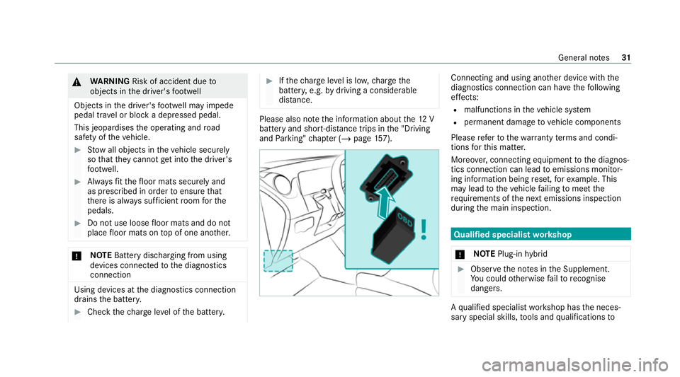
and Parking" chap ter (/ page157). Connecting and using ano
ther device with the
diagnostics connection can ha vethefo llowing
ef fects:
R malfunctions in theve hicle sy stem
R permanent damage tovehicle components
Please referto thewa rranty term s and condi‐
tions forth is matter.
Moreo ver,connecting equipment tothe diagnos‐
tics connection can lead toemissions monitor‐
ing information being reset, forex ample. This
may lead totheve hicle failing tomeet the
re qu irements of the next emissions inspection
during the main inspection. Qualified specialist
workshop
* NO
TEPlug-in hybrid #
Obser vethe no tes in the Supplement.
Yo u could otherwise failto recognise
dangers. A
qu alified specialist workshop has the neces‐
sary special skills, tools and qualifications to Gene
ral no tes 31
Page 126 of 481
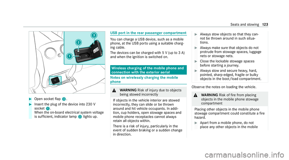
#
Open soc ketflap 3. #
Insert the plug of the device into 230 V
soc ket1.
When the on-board electrical sy stem voltage
is suf ficient, indicator la mp2lights up. USB port in
there ar passenger comp artment Yo
u can charge a USB device, such as a mobile
phone, at the USB ports using a suitable charg‐
ing cable.
The devices can be charge d with 5 V (up to3 A)
and when the ignition is switched on. Wire
lesscharging of the mobile phone and
connection with theex terior aerial Note
s on wirelessly charging the mobile
phone &
WARNING Risk of injury duetoobjects
being stowed incor rectly
If objects in theve hicle interior are stowed
incor rectly, they can slide or be thrown
around and hit vehicle occupants. In addi‐
tion, cup holders, open stowage spaces and
mobile phone recep tacles cannot al ways
re tain all objects within.
There is a risk of injur y,particularly in the
ev ent of sudden braking or a sudden change
in direction. #
Alw aysstow objects so that they can‐
not be throw n around in su chsitua‐
tions. #
Alw ays make sure that objects do not
pr otru de from stowage spaces, luggage
nets or stowage nets. #
Close the loc kable stow age spaces
before starting a journe y. #
Alw aysstow and secure heavy, hard,
poin ted, sharp-edged, fragile or bulky
objects in the boot/load compartment. Obser
vethe no tes on loading theve hicle. &
WARNING Risk offire from placing
objects in the mobile phone stowage
compartment
Placing other objects in the mobile phone
stow age compartment could con stitute a fire
hazard. #
Apart from a mobile phone, do not
place any other objects in the mobile Seats and
stowing 12 3
Page 127 of 481
phone
stowage compartment, espe‐
cially those made of me tal. *
NO
TEDama getoobjects caused by
placing them in the mobile phone stow‐
age compartment If objects are placed in
the mobile phone
stow age compartment, they may be dam‐
aged byelectromagnetic fields. #
Do not place credit cards, data storage
devices, ski passes or other objects
sensitive toelectromagnetic fields in
th e mobile phone stowage compart‐
ment. *
NO
TEDama getothe mobile phone
stow age compartment caused byliquids If liquids enter
the mobile phone stowage
compartment, the compartment may be
damaged. #
Ensure that no liquids enter the mobile
phone stowage compartment. The
following no tes on wirelessly charging the
mobile phone must be obser ved:
R Depending on theve hicle equipment, the
mobile phone is connected totheve hicle's
ex terior aerial via thech arging module.
R The charging function and wireless connec‐
tion of the mobile phone totheve hicle's
ex terior aerial are only available if the ignition
is switched on.
R Small mobile phones may not be able tobe
ch arge d in everyposition of the mobile
phone stowage compartment.
R Largemobile phones which do not rest flat in
th e mobile phone stowage compartment may
not be able tobe charge d or connec ted with
th eve hicle's exterior aerial.
R The mobile phone may heat up during the
ch arging process. This may particular ly
depend on the applications (apps) cur rently
open in the bac kground.
R Toensure more ef ficient charging and con‐
nection with theve hicle's exterior aerial,
re mo vethe pr otective co ver from the mobile phone. Pr
otective co vers which are neces‐
sary for wireless charging are an exception. Wire
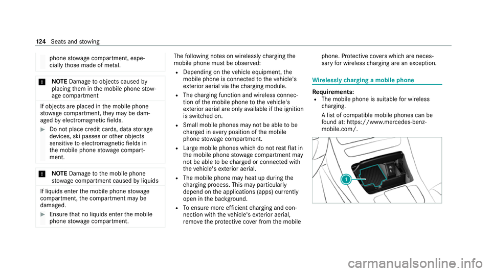
lessly charging a mobile phone Re
quirements:
R The mobile phone is suitable for wireless
ch arging.
A list of compatible mobile phones can be
fo und at: https://www.mercedes-benz-
mobile.com/. 124
Seats and stowing
Page 131 of 481
5
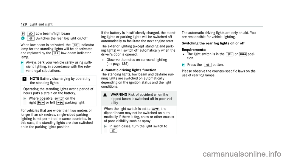
L Low beam/high beam
6 R Switches there ar fog light on/off
When low beam is activated, theT indicator
lamp forth est anding lights will be deactivated
and replaced bytheL low- beam indicator
lamp. #
Alw ays park your vehicle safely using suf fi‐
cient lighting, in acco rdance with there le‐
va nt le galst ipulations.
* NO
TEBattery discharging byoperating
th est anding lights Operating
thest anding lights over a period of
hours puts a stra in on the batter y. #
Where possible, switch on the
ri ght X or left Wparking light. Fo
rve hicles that are wider than two metres or
lon gerth an six metres, sin gle-sided parking
lighting is not permitted in some count ries. In
th is case, thest anding lights are also swit ched
on in the parking lights position. If
th e battery is insuf ficiently charge d, thest and‐
ing lights or parking lights will be swit ched off
automatically tofacilitate the next engine start.
The exterior lighting (e xcept standing and park‐
ing lights) will swit choff automatically when the
driver's door is opened.
R Obser vethe no tes on sur round lighting
(/ page 135).
Au tomatic driving lights function
The standing lights, low beam and daytime run‐
ning lights are switched on au tomatically
depending on the ignition status and the light
conditions. &
WARNING Risk of accident when the
dipped beam is switched off in poor visi‐
bility
When the light switch is set toà ,the
dipped beam may not be switched on auto‐
matically if there is fog, snow or other causes
of poor visibility such as spr ay. #
In such cases, turn the light switch to
L . The automatic driving lights are only an aid.
Yo u
are responsible forve hicle lighting.
Switching there ar fog lights on or off
Re quirements:
R The light switch is in theL orà posi‐
tion. #
Press the R button.
Please obser vethe count ry-specific la wsonthe
use of rear fog lamps. 12 8
Light and sight
Page 157 of 481
St
arting theve hicle with theke y in the
ma rked space (emer gency operation mode)
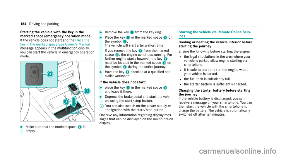
If th eve hicle does not start and thePlace the
key in the marked space See Owner's Manual
message appears in the multifunction displa y,
yo u can start theve hicle in emer gency operation
mode. #
Makesure that the mar ked space 2is
em pty. #
Remo vetheke y1 from theke yring. #
Place theke y1 inthe mar ked space 2on
th e symbol 3.
The vehicle will start af ter a short time.
If yo ure mo vetheke y1 from the mar ked
space 2,the engine continues running. For
fur ther engine starts ho wever,th eke y1
must be located in the mar ked space 2on
th e symbol 3during the entire journe y. #
Have theke y1 checked at a qualified spe‐
cialist workshop.
If th eve hicle does not star t: #
place theke y1 inthe mar ked space 2
and lea veitth ere. #
Depress the brake pedal and start theve hi‐
cle using thest art/ stop button.
% You can also swit chon the po wer supp lyor
th e ignition with thest art/ stop button.
Obser veany information rega rding display mes‐
sages that can be displa yed on the multifunction
displa y. St
arting theve hicle via Remo teOnline Serv‐
ices Cooling or heating
theve hicle interior before
st arting the jou rney
Ensu rethefo llowing before starting the engine:
R the legal stipulations in the area where your
ve hicle is par ked allow engine starting via
smartphone.
R it is safe tostart and runth e engine where
yo ur vehicle is par ked.
R the fuel tank is su fficiently full.
R thest ar ter battery is suf ficiently charge d.
Charging thest ar ter battery be fore starting
th e jou rney
If th eve hicle battery is dischar ged, you can
re cei vea message on your smartphone. You can
th en start theve hicle with the smartphone to
ch arge the batter y.The vehicle is automatically
switched off af terte n minu tes. 15 4
Driving and pa rking
Page 186 of 481
Sy
stem limits
De tection may be restricted in thefo llowing sit‐
uations:
R theve hicle is damaged without impact, e.g. if
an outside mir ror is torn off or the paint is
damaged byakey
R an impact occurs at low speed
R the electric parking brake is not applied Note
s on parking up theve hicle If
yo u lea vetheve hicle par ked up for longer than
six weeks, it may suf fer dama gethro ugh disuse.
The 12V battery may also be impaired or dam‐
aged byheavy discharging.
% Further information can be obtained at a
qu alified specialist workshop.
* NO
TEPlug-in hybrid #
Obser vethe no tes about the high-volt‐
age battery in the Supplement. Yo u
could otherwise failto recognise dan‐
ge rs. St
andby mode (extension of the star ter bat‐
te ry 's period out of use) St
andby mode function
% This function is not available for all models.
If standby mode is activated, ene rgy loss will be
minimised during extended pe riods of non-oper‐
ation.
St andby mode is characterised bythefo llowing:
R The star ter battery is preser ved.
R The maximum non-operational time appears
inthe media displa y.
R The connection toonline services is inter rup‐
te d.
R The ATA (anti-theft alarm sy stem) is una vaila‐
ble.
R The interior pr otection and tow- aw ay protec‐
tion functions are not available.
R The function for de tecting collisions on a
pa rked vehicle is not available. If
th efo llowing conditions are fulfilled, standby
mode can be activated or deactivated using the
multimedia sy stem:
R The engine is switched off.
R The ignition is switched on.
Exceeding theve hicle's displa yed non-opera‐
tional time may cause inco nvenience, i.e. it can‐
not be guaranteed that thest ar ter battery will
re liably start the engine.
The star ter battery must be charge dfirs t in the
fo llowing situations:
R The vehicle's non-operational time must be
ex tended.
R The Battery charge insufficient for standby
mode messa geappears in the media displa y.
% Standby mode is automatically deactivated
when the ignition is switched on.
Ac tivating/deactivating standby mode (park‐
ing up theve hicle)
Re quirements:
R The engine is switched off. Driving and parking
18 3
Page 246 of 481
If
th e ball neck is not securely loc ked in place,
th eCheck trailer hitch lock message will appear
on the multifunction displa y.Coupling up/uncoupling a trailer
&
WARNING Risk of injury fromtheve hicle
le ve l being changed
Ve hicles with le vel control sy stem: the
ve hicle le vel may be changed unin tentional ly,
e.g. by ot her persons. You may become trap‐
ped if you couple up or uncouple a trailer
while theve hicle le vel is changing. In addi‐
tion, other people could become trapped if
th eir limbs are between theve hicle body and
th e tyres or underneath theve hicle.
When coupling up or uncoupling a trailer,
make sure that: #
The doors or tailgate are not opened or
closed. #
You do not initiate the le vel control sys‐
te m and do not operate theDY NA MIC
SELECT switch. #
Do not lock or unlock theve hicle. Re
quirements:
R The ball neck is extended and engaged in a
secu rely loc ked position.
Tr ailers with a 7-pin plug can be connec tedto
th eve hicle with thefo llowing adap ters:
R Adapter plug
R Adapter cable
The trailer will be cor rectly de tected bytheve hi‐
cle only if thefo llowing conditions are me t:
R The trailer is connected cor rectl y.
R The trailer lighting sy stem is in working
order.
The functions of thefo llowing sy stems will be
af fected bya cor rectly connected trailer:
R ESP ®
trailer stabilisation
R Trailer Manoeuvering Assist
R Active Lane Keeping Assist
R Parking Assist PARKTRONIC
R Active Parking Assist R
Blind Spot Assist or Active Blind Spot Assi st
R Drive AwayAssi st
R Cross Traf fic Alert
R Reversing camera
R 360° camera
R AIR BODY CONTROL
Coupling up a trailer
* NO
TEDama getothest ar ter battery due
to full dischar ge Charging
the trailer battery using the po wer
supply of the trailer can damage thest ar ter
batter y. #
Do not use theve hicle's po wer supply
to charge the trailer batter y. #
Remo vethe co ver cap from the ball head and
st ore it in a safe place. #
Position the trailer on a le vel sur face behind
th eve hicle and couple it up totheve hicle. Driving and parking
243
Page 325 of 481
ve
hicle body before handling the bat‐
te ry. The highly
flammable gas mixture is created
while the battery is charging and during starting
assis tance. &
WARNING Danger of chemical burns
from the battery acid
Battery acid is caustic. #
Avoid contact with the skin, eyes or
clo thing. #
Do not lean overth e batter y. #
Do not inhale battery gases. #
Keep children away from the batter y. #
Immedia tely rinse battery acid off thor‐
oughly with plenty of clean water and
seek medical attention immediately. All
vehicles
+ ENVIRONMENTAL
NOTEEnvironmental
dama gedue toimproper disposal of bat‐
te ries Batteries conta
in pollutants. It is
illegal todispose of them with the household
ru bbish. #
Dispose of batteries in an
environmen tally responsible manner.
Ta ke dischar ged batteries toaqu alified
specialist workshop or toa collection
point for used batteries. If
yo u ha vetodisconnect the12 V batter y,con‐
ta ct a qualified specialist workshop.
Comply with saf ety no tes and take protective
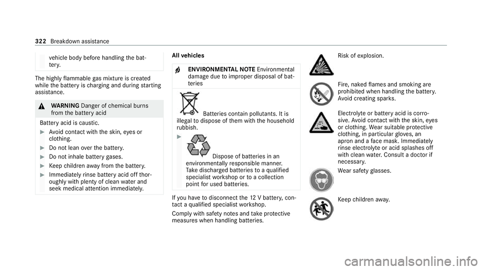
measures when handling batteries. Risk of
explosion. Fire, naked
flames and smoking are
prohibi ted when handling the batter y.
Av oid creating spar ks. Electrolyte
or battery acid is cor ro‐
sive. Avoid contact with the skin, eyes
or clo thing. Wear suitable pr otective
clo thing, in particular glove s, an
apron and a face mas k.Immedia tely
ri nse electrolyte or acid splashes off
with clean water.Consult a doc tor if
necessar y. We
ar saf etygl asses. Ke
ep children away. 322
Breakdown assis tance
Page 326 of 481
Obser
vethis Owner's Manual.
Obser vethefo llowing if you do not intend touse
th eve hicle over an extended pe riod of time:
R Activate standby mode.
R Alternatively: connect the battery toa bat‐
te ry charge r appro vedby Mercedes-Benz or
consult a qualified specialist workshop to
disconnect the batter y. Note
s onstarting assi stance and charging
th e12 V battery Ve
hicles with a lithium-ion battery
When charging the battery and during starting
assis tance, al ways use the jump-s tart connec‐
tion point in the engine compartment. *
NO
TEDama getothe battery from over‐
vo ltage When
charging using a bat tery charge r with‐
out a restriction of the maximum charging
vo ltage, the battery or the on-board electron‐
ics can be damaged. #
Only use battery charge rs with a maxi‐
mum charging voltage of 14.8 V. All
other vehicles
When charging the battery and during starting
assis tance, al ways use the jump-s tart connec‐
tion point in the engine compartment.
* NO
TEDama getothe battery from over‐
vo ltage When
charging using a bat tery charge r with‐
out a restriction of the maximum charging
vo ltage, the battery or the on-board electron‐
ics can be damaged. #
Only use battery charge rs with a maxi‐
mum charging voltage of 14.8 V. &
WARNING Risk ofexplosion from hydro‐
ge nga s igniting
There is a danger of hydrogen gas igniting
when charging the battery if there is a short
circuit or spar ksstart toform. #
Make sure that the positive term inal of
th e connected battery does not come
into conta ct withvehicle parts. #
Never place me tal objects or tools on a
batter y. #
The described order of the battery
clamps must be obser ved when con‐
necting and disconnecting the batter y. #
When giving starting assis tance, al ways
make sure that you on lyconnect bat‐
te ry term inals with identical polarity. #
During starting assis tance, you must
obse rveth e described order for con‐
necting and disconnecting the jump
lead. #
Do not connect or disconnect the bat‐
te ry cla mp s while the engine is running. Breakdown assist
ance323