fuel cap MERCEDES-BENZ GLC SUV 2015 Owners Manual
[x] Cancel search | Manufacturer: MERCEDES-BENZ, Model Year: 2015, Model line: GLC SUV, Model: MERCEDES-BENZ GLC SUV 2015Pages: 497, PDF Size: 15.27 MB
Page 14 of 497
Vehicle ........................................... 102
Engine
Display message ............................ 353
ECO start/stop function ................ 191
Engine number ............................... 480
Jump-starting .................................4 43
Running irregularl y......................... 194
Starting (important safety notes )... 189
Starting problems .......................... 194
Starting the engine with the key .... 189
Starting with the Start/Stop but-
ton ................................................. 190
Stopping ........................................ 220
Tow-starting (vehicle) ..................... 448
Warning lamp (engine diagnos-
tics) ............................................... 384
Engine electronics
Notes ............................................. 478
Problem (fault) ............................... 194
Engine oil
Additives ........................................ 486
Checking the oil level ..................... 416
Checking the oil level using the
dipstick .......................................... 416
Display message ............................ 355
Filling capacity ............................... 486
General notes ................................ 485
Notes about oil grade s................... 485
Notes on oil level/consumption .... 416
Topping up ..................................... 416
Viscosity ........................................ 486
Environmental protection
Returning an end-of-life vehicle ....... 25
ESP ®
(Electronic Stability Pro-
gram)
Activating/deactivating ................... 86
Characteristics ................................. 85
Crosswind Assist ............................. 87
Display message ............................ 336
Function/note s................................ 84
General notes .................................. 84
Important safety guidelines ............. 85
Trailer stabilisation .......................... 86
Warning lamp ................................. 381
ETS/4ETS (Electronic Traction Sys-
tem) ...................................................... 85
Exhaust
see Exhaust pipe Exhaust pipe
Cleaning ......................................... 426
Exhaustive discharging (high-volt-
age battery) ....................................... 440
Exterior lighting
Cleaning ......................................... 424
see Lights
Exterior mirrors
Adjusting ....................................... 132
Anti-dazzle mode (automatic) ........ 133
Folding in/out (automatically )....... 132
Folding in/out (electrically) ........... 132
Out of position (troubleshooting) ... 133
Parking position ............................. 133
Resetting ....................................... 132
Storing settings (memory func-
tion) ............................................... 135 F
Fault message see Display messages
Features ............................................. 402
Filler cap
see Fuel filler flap
Fire extinguisher ............................... 432
First-aid kit ......................................... 431
Fitting a wheel
Fitting a wheel ............................... 467
Lowering the vehicle ...................... 467
Preparing the vehicle ..................... 464
Raising the vehicle ......................... 465
Removing a whee l.......................... 466
Securing the vehicle against roll-
ing away ........................................ 465
Flat tyre
Changing a wheel/fitting the
spare whee l................................... 463
MOExtended tyre s......................... 434
Preparing the vehicle ..................... 433
TIREFIT kit ...................................... 435
see Emergency spare wheel
Floormat ............................................. 411
Foglamps (extended range) .............. 143
Frequencies
Mobile phone ................................. 478
Two-way radio ................................ 478 Index
11
Page 15 of 497
Front-passenger front airbag deac-
tivation
Display message ............................ 349
Front-passenger front airbag deac-
tivation system
Operation ........................................ .57
Problems ......................................... 61
System self-test ...............................59
Fuel
Additives ........................................ 483
Consumption information .............. 484
Consumption statistics .................. 319
Displaying the current consump-
tion ................................................ 318
Displaying the range ...................... 318
Driving tips .................................... 222
E10 ................................................ 482
Fuel gauge ...................................... .34
Grade (petrol) ................................ 482
Important safety notes .................. 481
Low outside temperatures ............ .483
Problem (malfunction) ................... 206
Quality (diesel )............................... 483
Refuelling ....................................... 203
Tank content/reserve fue l............. 482
Fuel filler flap
Opening ......................................... 205
Fuel filter (white display message) .. 356
Fuel level
Calling up the range (on-board
computer) ...................................... 318
Gaug e.............................................. 34
Fuel tank
Capacity ........................................ 482
Problem (malfunction) ................... 206
Fuses
Allocation chart ............................. 451
Before changing ............................. 449
Dashboard fuse box ....................... 449
Fuse box in the engine compart-
ment .............................................. 450
Fuse box in the front-passenger
footwell .......................................... 449
Fuse box in the luggage compart-
ment .............................................. 451
Important safety notes .................. 448 G
Gearshift paddles see Steering wheel gearshift paddles
Genuine Mercedes-Benz parts ........... 25
Glove compartment .......................... 391 H
HANDS-FREE ACCESS ....................... 106
Hazard warning lamps ...................... 141
Head restraint
General notes ................................ 124
Head restraints
Adjusting (electrically) ................... 124
Adjusting (manually) ...................... 124
Adjusting (rear) .............................. 125
Adjusting the fore-and-aft posi-
tion manually ................................. 124
Fitting/removing (rear) .................. 125
Important safety notes .................. 123
Head-up display
Adjusting the brightness ................ 331
Displays and operating .................. 316
Function/note s............................. 315
Important safety notes .................. 316
Selecting displays .......................... 330
Setting the position ....................... 331
Storing settings (memory func-
tion) ............................................... 135
Headlamp
Cleaning system (notes) ................ 487
Headlamp flasher .............................. 141
Headlamps
Misting up ...................................... 144
see Automatic headlamp mode
Heating
see Climate control
High-pressure cleaners .................... 422
High-voltage battery
Battery car e................................... 212
Charging (charging station) ............ 217
Charging (mains socket) ................ 213
Charging (wallbox) ......................... 216
Charging cable heating up ............. 212
Energy consumption ...................... 212
General notes .................................. 45
Method of operation ...................... 211 12
Index
Page 37 of 497
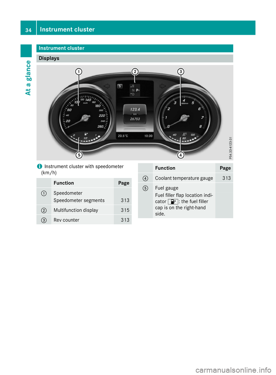
Instrument cluster
Displays
i
Instrument cluster with speedometer
(km/h) Function Page
:
Speedometer
Speedometer segments 313
;
Multifunction display 315
=
Rev counter 313 Function Page
?
Coolant temperature gauge 313
A
Fuel gauge
Fuel filler flap location indi-
cator 8: the fuel filler
cap is on the right-hand
side. 34
Instrument clusterAt a glance
Page 38 of 497
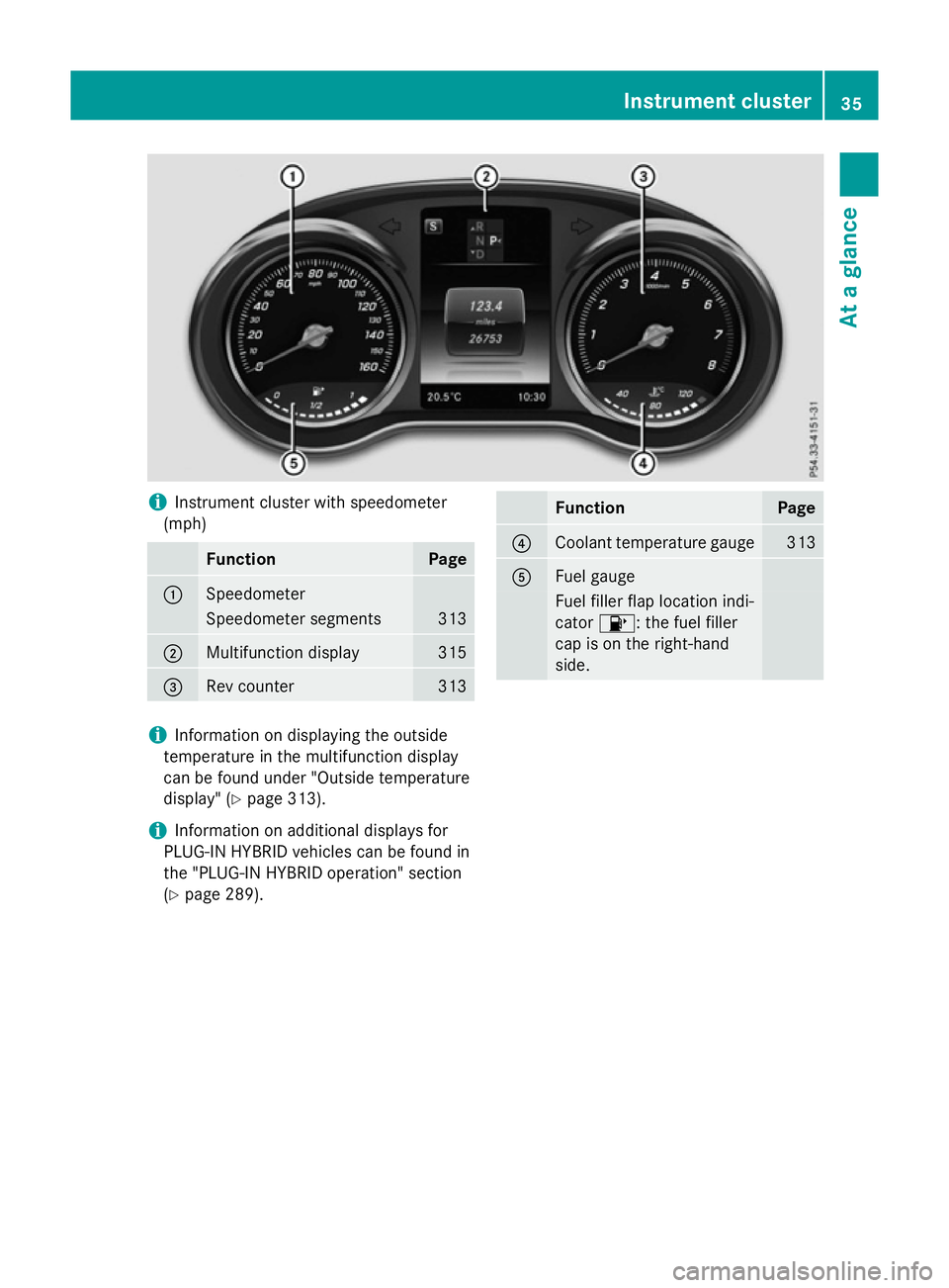
i
Instrument cluster with speedometer
(mph) Function Page
:
Speedometer
Speedometer segments 313
;
Multifunction display 315
=
Rev counter 313 Function Page
?
Coolant temperature gauge 313
A
Fuel gauge
Fuel filler flap location indi-
cator
8: the fuel filler
cap is on the right-hand
side. i
Information on displaying the outside
temperature in the multifunction display
can be found under "Outside temperature
display" (Y page 313).
i Information on additional displays for
PLUG-IN HYBRID vehicles can be found in
the "PLUG-IN HYBRID operation" section
(Y page 289). Instrument cluster
35At a glance
Page 107 of 497
X
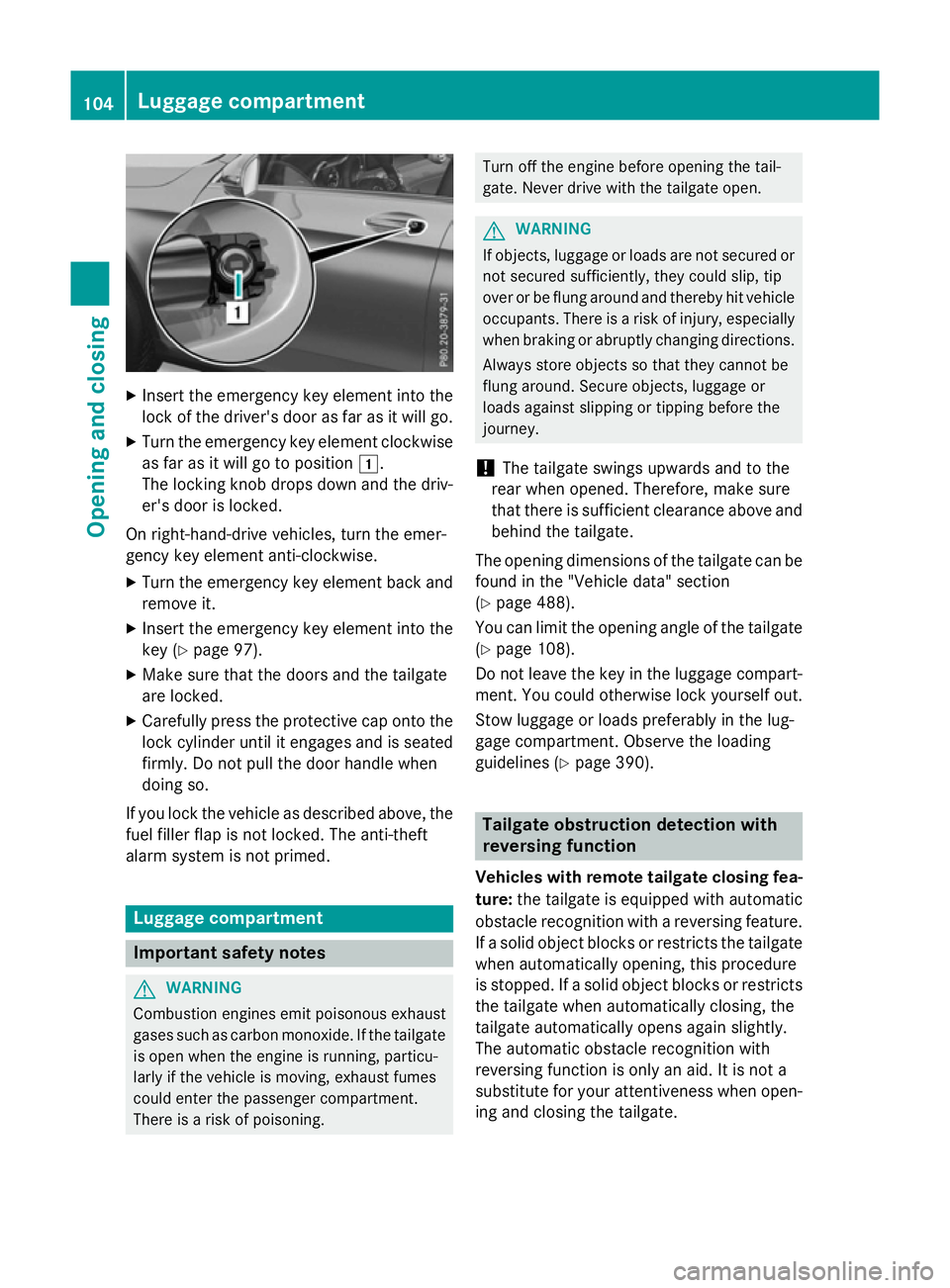
Insert the emergency key element into the
lock of the driver's door as far as it will go.
X Turn the emergency key element clockwise
as far as it will go to position 1.
The locking knob drops down and the driv- er's door is locked.
On right-hand-drive vehicles, turn the emer-
gency key element anti-clockwise.
X Turn the emergency key element back and
remove it.
X Insert the emergency key element into the
key (Y page 97).
X Make sure that the doors and the tailgate
are locked.
X Carefully press the protective cap onto the
lock cylinder until it engages and is seated firmly. Do not pull the door handle when
doing so.
If you lock the vehicle as described above, the
fuel filler flap is not locked. The anti-theft
alarm system is not primed. Luggage compartment
Important safety notes
G
WARNING
Combustion engines emit poisonous exhaust
gases such as carbon monoxide. If the tailgate is open when the engine is running, particu-
larly if the vehicle is moving, exhaust fumes
could enter the passenger compartment.
There is a risk of poisoning. Turn off the engine before opening the tail-
gate. Never drive with the tailgate open. G
WARNING
If objects, luggage or loads are not secured or not secured sufficiently, they could slip, tip
over or be flung around and thereby hit vehicle
occupants. There is a risk of injury, especially when braking or abruptly changing directions.
Always store objects so that they cannot be
flung around. Secure objects, luggage or
loads against slipping or tipping before the
journey.
! The tailgate swings upwards and to the
rear when opened. Therefore, make sure
that there is sufficient clearance above and behind the tailgate.
The opening dimensions of the tailgate can be
found in the "Vehicle data" section
(Y page 488).
You can limit the opening angle of the tailgate
(Y page 108).
Do not leave the key in the luggage compart- ment. You could otherwise lock yourself out.
Stow luggage or loads preferably in the lug-
gage compartment. Observe the loading
guidelines (Y page 390). Tailgate obstruction detection with
reversing function
Vehicles with remote tailgate closing fea- ture: the tailgate is equipped with automatic
obstacle recognition with a reversing feature. If a solid object blocks or restricts the tailgate
when automatically opening, this procedure
is stopped. If a solid object blocks or restricts the tailgate when automatically closing, the
tailgate automatically opens again slightly.
The automatic obstacle recognition with
reversing function is only an aid. It is not a
substitute for your attentiveness when open- ing and closing the tailgate. 104
Luggage compartmentOpening and closing
Page 181 of 497
X
To activate or deactivate "Immediate
pre-entry climate control": press rocker
switch :up or down.
The blue or red indicator lamp above the
rocker switch lights up or goes out.
The colours of the indicator lamps in rocker
switch :have the following meanings:
R blue: cooling activated
R red: heating activated
R yellow: departure time is preselected Auxiliary heating
Important safety notes G
DANGER
If the exhaust pipe is blocked or sufficient
ventilation is not possible, toxic exhaust
fumes can enter the vehicle, especially car-
bon monoxide. This is the case, e.g. in
enclosed spaces, or if the vehicle is stuck in
snow. There is a risk of fatal injuries.
You should switch off the auxiliary heating in
enclosed spaces which do not have an extrac- tion system, e.g. a garage. If the vehicle is
stuck in snow and you must leave the auxiliary
heating running, keep the exhaust pipe and
the area around the vehicle clear of snow. To guarantee a sufficient supply of fresh air, open
a window on the side of the vehicle away from the wind. G
WARNING
When the auxiliary heating is switched on,
parts of the vehicle can become very hot.
Flammable materials such as leaves, grass or twigs may ignite if they come into contact
with:
R hot parts of the exhaust system
R the exhaust gas itself
There is a risk of fire. When the auxiliary heating is switched on,
make sure that:
R no flammable materials come into contact
with hot vehicle components
R the exhaust gas can escape from the
exhaust pipe unhindered
R the exhaust gas does not come into contact
with flammable materials.
The auxiliary heating is fitted under the front
wing on the right-hand side of the vehicle. The emissions outlet is found behind the front
wheel on the right-hand side of the vehicle.
! Operating the auxiliary heating/ventila-
tion draws on the vehicle battery. After you have heated or ventilated the vehicle a
maximum of two times, drive for a longer
distance.
Switch the auxiliary heating on regularly once a month for about ten minutes.
The auxiliary heating heats the air in the vehi-
cle interior to the set temperature. This
occurs without using the heat of the running
engine. The auxiliary heating is operated
directly using the vehicle's fuel. For this rea-
son, the tank content must be at least at
reserve fuel level to ensure that the auxiliary
heating functions.
The auxiliary heating or auxiliary ventilation
automatically adjusts to changes in temper-
ature and weather conditions. For this rea-
son, the auxiliary heating could switch from
ventilation mode to heating mode or from
heating mode to ventilation mode.
The auxiliary heating switches off when the
engine is switched off. The auxiliary ventila-
tion is not active if the engine is running.
The auxiliary heating or auxiliary ventilation
switches off automatically after 50 minutes.
This time limit can be altered. To do this, visit a qualified specialist workshop.
You cannot use the auxiliary ventilation to
cool the vehicle interior to a temperature
lower than the outside temperature. 178
Operating the climate control systemClimate control
Page 207 of 497
vapours. Keep fuels out of the reach of chil-
dren.
If you or others come into contact with fuel,
observe the following:
R Wash the fuel off any affected areas of skin
with water and soap immediately.
R If you get fuel in your eyes, rinse them thor-
oughly with clean water immediately. Seek
immediate medical attention.
R If fuel is swallowed, seek immediate medi-
cal attention. Do not induce vomiting.
R Change any clothing that has come into
contact with fuel immediately. G
WARNING
Electrostatic charge can cause sparks and
thereby ignite fuel vapours. There is a risk of
fire and explosion.
Always touch the vehicle body before opening the fuel filler flap or touching the fuel pump
nozzle. This discharges any electrostatic
charge that may have built up.
Do not get into the vehicle again during the
refuelling process. Otherwise, electrostatic
charge could build up again. G
WARNING
Vehicles with a diesel engine:
If you mix diesel fuel with petrol, the flash
point of this fuel mixture is lower than that of pure diesel fuel. When the engine is running,
components in the exhaust system may over-
heat unnoticed. There is a risk of fire.
Never refuel with petrol. Never add petrol to
diesel fuel.
! Do not use diesel to refuel vehicles with a
petrol engine. Do not switch on the ignition if you accidentally refuel with the wrong
fuel. Otherwise, the fuel will enter the fuel
system. Even small amounts of the wrong
fuel can result in damage to the fuel system
and the engine. Notify a qualified specialist
workshop and have the fuel tank and fuel
lines drained completely. !
Do not use petrol to refuel vehicles with a
diesel engine. Do not switch on the ignition if you accidentally refuel with the wrong
fuel. Otherwise, fuel can enter the fuel sys-tem. Even small amounts of the wrong fuel
could result in damage to the fuel system
and the engine. The repair costs are high.
Notify a qualified specialist workshop and
have the fuel tank and fuel lines drained
completely.
! Overfilling the fuel tank could damage the
fuel system.
! Take care not to spill any fuel on painted
surfaces. You could otherwise damage the
paintwork.
! Use a filter when adding fuel from a fuel
can. The fuel lines and/or the fuel injection
system could otherwise be blocked by par- ticles from the fuel can.
If you overfill the fuel tank, some fuel may
spray out when you remove the fuel pump
nozzle.
Further information on fuel and fuel quality
(Y page 480). Refuelling
General notes Observe the important safety notes
(Y
page 203).
If you unlock/lock the vehicle from the out-
side, the fuel filler flap also unlocks/locks.
The position of the 8fuel filler cap is dis-
played in the instrument cluster. The arrow
next to the filling pump indicates the side of
the vehicle. 204
RefuellingDriving and parking
Page 208 of 497
Opening the fuel filler flap
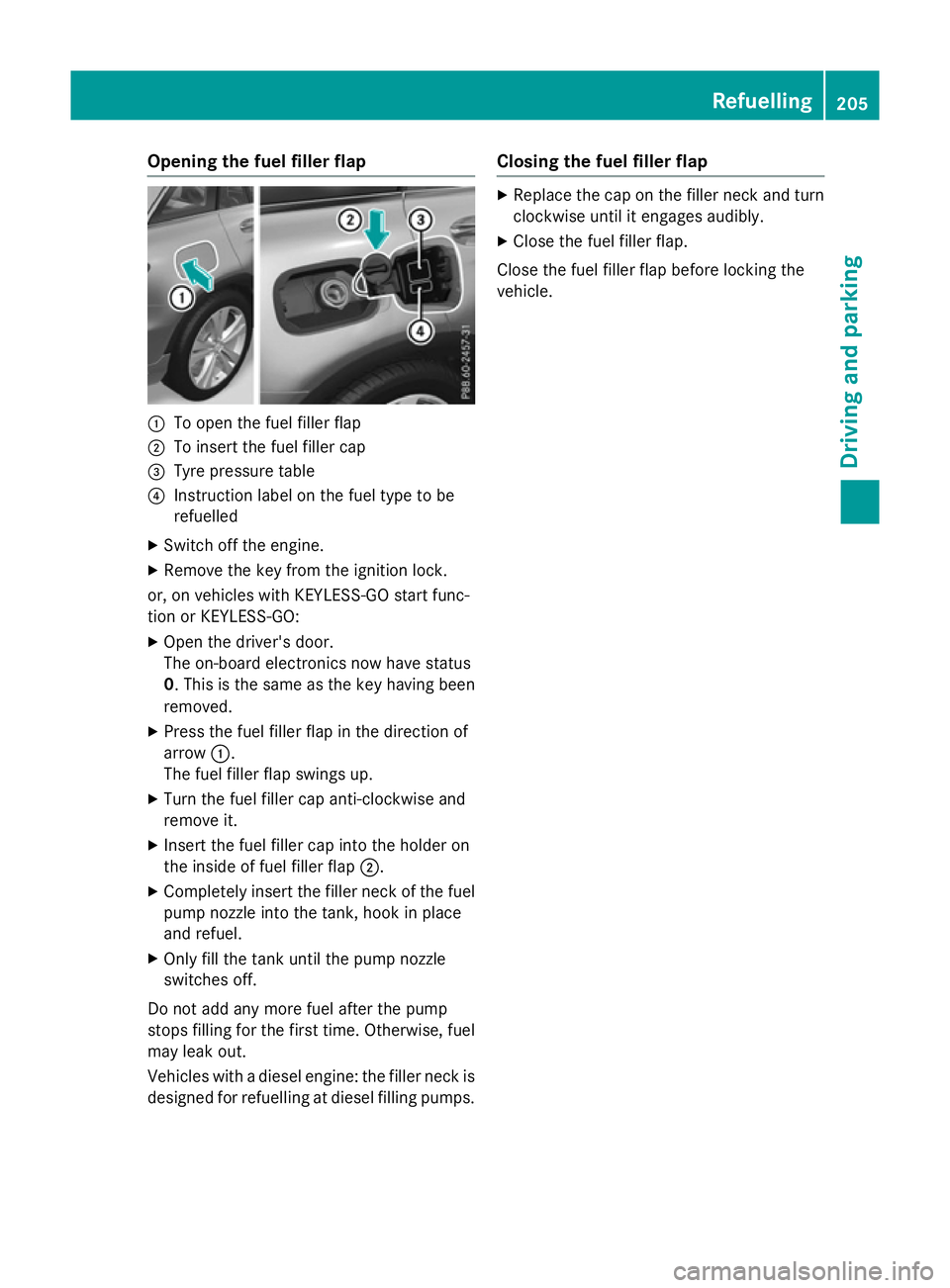
:
To open the fuel filler flap
; To insert the fuel filler cap
= Tyre pressure table
? Instruction label on the fuel type to be
refuelled
X Switch off the engine.
X Remove the key from the ignition lock.
or, on vehicles with KEYLESS-GO start func-
tion or KEYLESS‑ GO:
X Open the driver's door.
The on-board electronics now have status
0. This is the same as the key having been
removed.
X Press the fuel filler flap in the direction of
arrow :.
The fuel filler flap swings up.
X Turn the fuel filler cap anti-clockwise and
remove it.
X Insert the fuel filler cap into the holder on
the inside of fuel filler flap ;.
X Completely insert the filler neck of the fuel
pump nozzle into the tank, hook in place
and refuel.
X Only fill the tank until the pump nozzle
switches off.
Do not add any more fuel after the pump
stops filling for the first time. Otherwise, fuel
may leak out.
Vehicles with a diesel engine: the filler neck is designed for refuelling at diesel filling pumps. Closing the fuel filler flap X
Replace the cap on the filler neck and turn
clockwise until it engages audibly.
X Close the fuel filler flap.
Close the fuel filler flap before locking the
vehicle. Refuelling
205Driving and parking Z
Page 211 of 497
with the vehicle parked on a level surface.
Fluctuations in capacity will thus be avoi-
ded. Filling a vehicle standing on an uneven surface is not permitted. There is a danger
of overfilling, which can cause damage to
BlueTEC exhaust gas aftertreatment com-
ponents.
! Surfaces which have come into contact
with AdBlue ®
while refilling should be
rinsed immediately with water, or remove
AdBlue ®
with a moist cloth and cold water.
If AdBlue ®
has already crystallised, use a
sponge and cold water to clean the area.
AdBlue ®
residue crystallises after a certain
amount of time and soils the affected sur-
faces.
! AdBlue ®
is not a fuel additive and must
not be added to the fuel tank. If AdBlue ®
is
added to the fuel tank, this can lead to
engine damage.
Have the AdBlue ®
tank refilled at a qualified
specialist workshop. However, you can also
top up the AdBlue ®
tank:
R at a filling station with an AdBlue ®
filling
pump
R with AdBlue ®
refill bottles
R with an AdBlue ®
refill canister
When the pump nozzle switches off automat- ically during filling at a filling pump, the
AdBlue ®
tank has been completely filled. Do
not fill the AdBlue ®
tank any further. AdBlue ®
may leak out.
To avoid transporting already opened refill
containers in the vehicle, completely empty
refill bottles or canisters when filling the
AdBlue ®
tank, if possible.
Further information on AdBlue ®
(Y page 484). Opening the AdBlue
®
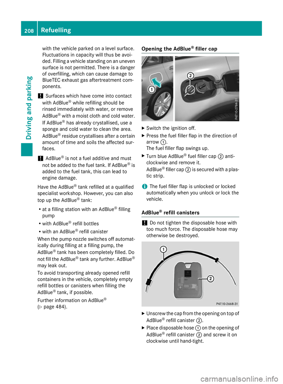
filler cap X
Switch the ignition off.
X Press the fuel filler flap in the direction of
arrow :.
The fuel filler flap swings up.
X Turn blue AdBlue ®
fuel filler cap ;anti-
clockwise and remove it.
AdBlue ®
filler cap ;is secured with a plas-
tic strip.
i The fuel filler flap is unlocked or locked
automatically when you unlock or lock the
vehicle.
AdBlue ®
refill canisters !
Do not tighten the disposable hose with
too much force. The disposable hose may
otherwise be destroyed. X
Unscrew the cap from the opening on top of
AdBlue ®
refill canister ;.
X Place disposable hose :on the opening of
AdBlue ®
refill canister ;and screw it on
clockwise until hand-tight. 208
RefuellingDriving and parking
Page 212 of 497
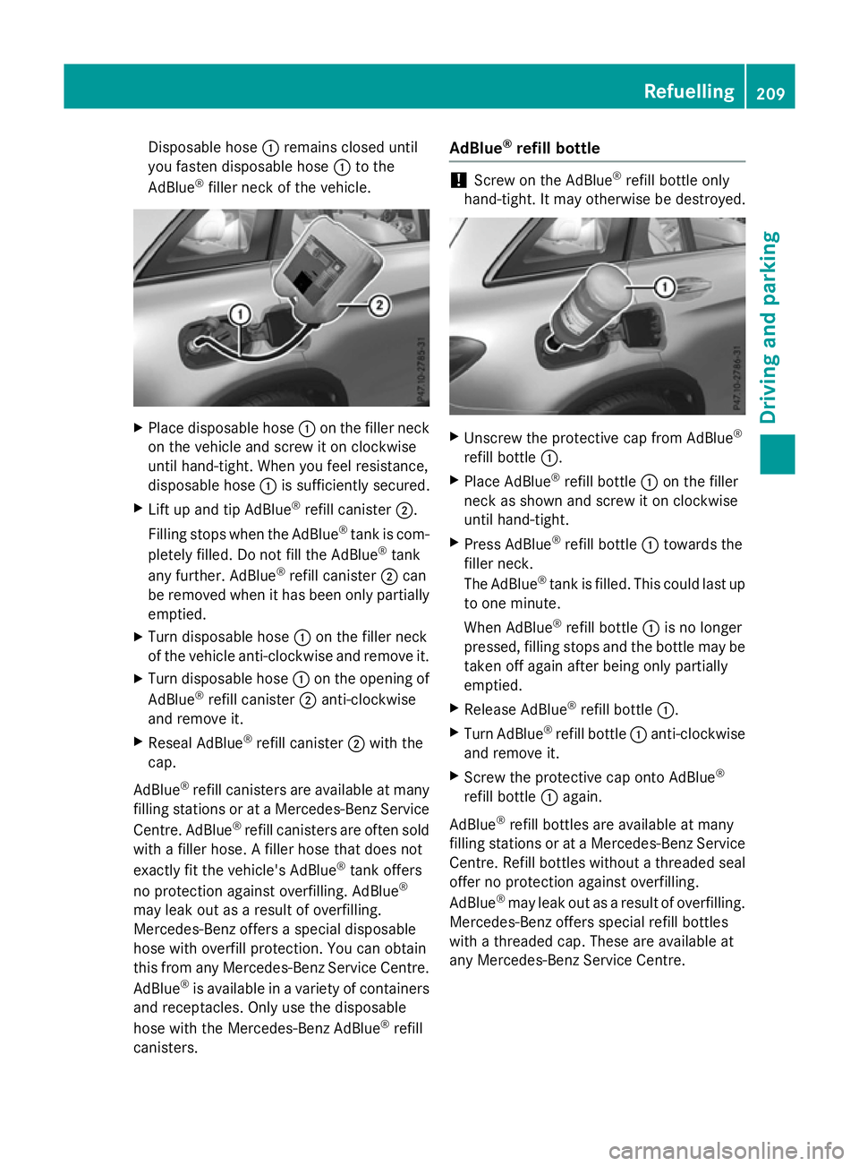
Disposable hose
:remains closed until
you fasten disposable hose :to the
AdBlue ®
filler neck of the vehicle. X
Place disposable hose :on the filler neck
on the vehicle and screw it on clockwise
until hand-tight. When you feel resistance,
disposable hose :is sufficiently secured.
X Lift up and tip AdBlue ®
refill canister ;.
Filling stops when the AdBlue ®
tank is com-
pletely filled. Do not fill the AdBlue ®
tank
any further. AdBlue ®
refill canister ;can
be removed when it has been only partially emptied.
X Turn disposable hose :on the filler neck
of the vehicle anti-clockwise and remove it.
X Turn disposable hose :on the opening of
AdBlue ®
refill canister ;anti-clockwise
and remove it.
X Reseal AdBlue ®
refill canister ;with the
cap.
AdBlue ®
refill canisters are available at many
filling stations or at a Mercedes-Benz Service
Centre. AdBlue ®
refill canisters are often sold
with a filler hose. A filler hose that does not
exactly fit the vehicle's AdBlue ®
tank offers
no protection against overfilling. AdBlue ®
may leak out as a result of overfilling.
Mercedes-Benz offers a special disposable
hose with overfill protection. You can obtain
this from any Mercedes-Benz Service Centre.
AdBlue ®
is available in a variety of containers
and receptacles. Only use the disposable
hose with the Mercedes-Benz AdBlue ®
refill
canisters. AdBlue
®
refill bottle !
Screw on the AdBlue ®
refill bottle only
hand-tight. It may otherwise be destroyed. X
Unscrew the protective cap from AdBlue ®
refill bottle :.
X Place AdBlue ®
refill bottle :on the filler
neck as shown and screw it on clockwise
until hand-tight.
X Press AdBlue ®
refill bottle :towards the
filler neck.
The AdBlue ®
tank is filled. This could last up
to one minute.
When AdBlue ®
refill bottle :is no longer
pressed, filling stops and the bottle may be
taken off again after being only partially
emptied.
X Release AdBlue ®
refill bottle :.
X Turn AdBlue ®
refill bottle :anti-clockwise
and remove it.
X Screw the protective cap onto AdBlue ®
refill bottle :again.
AdBlue ®
refill bottles are available at many
filling stations or at a Mercedes-Benz Service Centre. Refill bottles without a threaded seal
offer no protection against overfilling.
AdBlue ®
may leak out as a result of overfilling.
Mercedes-Benz offers special refill bottles
with a threaded cap. These are available at
any Mercedes-Benz Service Centre. Refuelling
209Driving and parking Z