width MERCEDES-BENZ GLC SUV 2015 Owners Manual
[x] Cancel search | Manufacturer: MERCEDES-BENZ, Model Year: 2015, Model line: GLC SUV, Model: MERCEDES-BENZ GLC SUV 2015Pages: 497, PDF Size: 15.27 MB
Page 228 of 497
If the brakes have been used only moderately,
you should occasionally test their effective-
ness. To do this, brake more firmly from a
higher speed while paying attention to the
traffic conditions. This improves the grip of
the brakes.
Wet road surfaces If you have driven for a long time in heavy rain
without braking, there may be a delayed reac-
tion from the brakes when braking for the first time. This may also occur after a car wash orafter driving through deep water.
You will have to depress the brake pedal more
firmly. Maintain a greater distance to the vehi-
cle in front.
After driving on a wet road or having the vehi- cle washed, brake firmly while paying atten-
tion to the traffic conditions. This will warm up
the brake discs, thereby drying them more
quickly and protecting them against corro-
sion.
Limited braking performance on salt-
treated roads If you drive on salt-treated roads, a layer of
salt may form on the brake discs and pads.
This can increase the braking distance con-
siderably.
R In order to prevent a layer of salt forming,
apply the brakes occasionally while paying
attention to the traffic conditions.
R Carefully depress the brake pedal at the
end of the journey and when starting the
next journey.
R Maintain a much greater distance to the
vehicle in front.
New brake discs and brake pads/
linings Brake pads/linings and discs that are either
new or have been replaced only achieve opti-
mum braking effect after several hundred kil-
ometres of driving. Compensate for the reduced braking effect by applying greater
force to the brake pedal.
For safety reasons, Mercedes-Benz recom-
mends only fitting the following brake discs
and brake pads/linings:
R brake discs that have been approved by
Mercedes-Benz
R brake pads/linings that have been
approved by Mercedes-Benz or that are of
an equivalent standard of quality
Other brake discs or brake pads/linings can
compromise the safety of your vehicle.
Always replace all brake discs and brake
pads/linings on an axle at the same time.
Always fit new brake pads/linings when
replacing brake discs.
The vehicle is equipped with lightweight
brake discs to which the wheel assembly with
rim and threaded connection is matched.
The use of brake discs other than those
approved by Mercedes-Benz may alter track
width and is subject to approval, if applicable.
Shock-type loads when handling the brake
discs, such as when changing wheels, can
lead to a reduction in comfort when driving
with lightweight brake discs. Avoid shock-
type loads on the lightweight brake discs,
particularly on the brake plate. Driving on wet roads
Aquaplaning If water has accumulated to a certain depth
on the road surface, there is a danger of aqua-
planing occurring, even if:
R you are driving at low speeds
R the tyres have adequate tread depth
For this reason, drive in the following manner in the event of heavy rain or in conditions in
which aquaplaning can occur:
R lower your speed
R avoid tyre ruts Driving tips
225Driving and parking Z
Page 247 of 497
Tips for driving with DISTRONIC PLUS
General notes
Pay particular attention in the following traffic
situations:
R Cornering, entering and exiting a bend
R Vehicles which are not driving in the middle
of their lane
R Other vehicles changing lane
R Narrow vehicles
R Obstructions and stationary vehicles
R Crossing vehicles
In such situations, brake if necessary.
DISTRONIC PLUS is then deactivated.
Cornering, entering and exiting a bend The ability of DISTRONIC PLUS to detect vehi-
cles when cornering is limited. Your vehicle
may brake unexpectedly or late.
Vehicles which are not driving in the mid- dle of their lane DISTRONIC PLUS may not detect vehicles
which are not driving in the middle of their lane. The distance to the vehicle in front will
be too short.
Other vehicles changing lane
DISTRONIC PLUS has not detected the vehi-
cle cutting in yet. The distance to this vehicle
will be too short.
Narrow vehicles DISTRONIC PLUS has not yet detected the
vehicle in front on the edge of the carriageway
because of its narrow width. The distance to
the vehicle in front will be too short.
Obstructions and stationary vehicles 244
Driving systemsDriving an
d parking
Page 266 of 497
Activating/deactivating the reversing
camera X
To activate: make sure that the key is in
position 2in the ignition lock.
X Make sure that the Activation by R
Activation by R
gear
gear function is selected in Audio 20 or
COMAND Online (see the Digital Owner's
Manual).
X Engage reverse gear.
The reversing camera flap opens. The area
behind the vehicle is shown with guide lines
in the Audio 20 or COMAND Online display.
The image from the reversing camera is
available throughout the manoeuvring
process.
X To change the function mode for vehi-
cles with trailer tow hitch: using the
Audio 20 or COMAND Online controller,
select symbol :for the "Reverse parking"
function or symbol ;for "Coupling up a
trailer".
The symbol of the selected function is high-
lighted.
To deactivate: the reversing camera deacti-
vates if you shift the transmission to Por after
driving forwards a short distance. Messages in the Audio 20 or COMAND
Online display The reversing camera may show a distorted
view of obstacles or show them incorrectly or
not at all. Obstacles are not shown by the
reversing camera in the following locations:
R very close to the rear bumper
R under the rear bumper
R in the area immediately above the boot lid
handle or tailgate handle
! Objects not at ground level may appear to
be further away than they actually are, e.g.:
R the bumper of a parked vehicle
R the drawbar of a trailer
R the ball coupling of a trailer tow hitch
R the rear section of an HGV
R a slanted post
Use the guidelines only for orientation.
Approach objects no further than the bot-
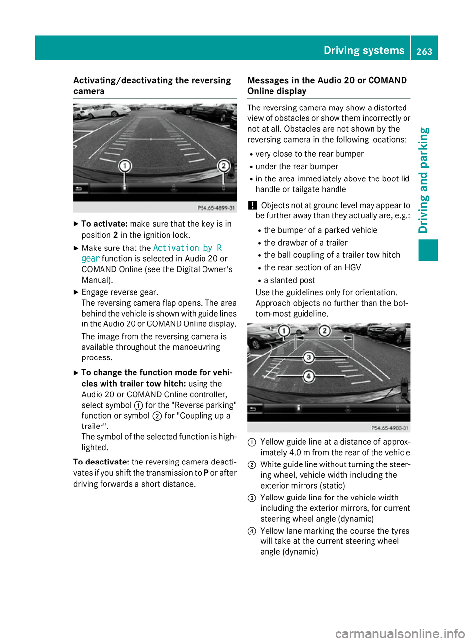
tom-most guideline. :
Yellow guide line at a distance of approx-
imately 4.0 mfrom the rear of the vehicle
; White guide line without turning the steer-
ing wheel, vehicle width including the
exterior mirrors (static)
= Yellow guide line for the vehicle width
including the exterior mirrors, for current
steering wheel angle (dynamic)
? Yellow lane marking the course the tyres
will take at the current steering wheel
angle (dynamic) Driving systems
263Driving and parking Z
Page 267 of 497
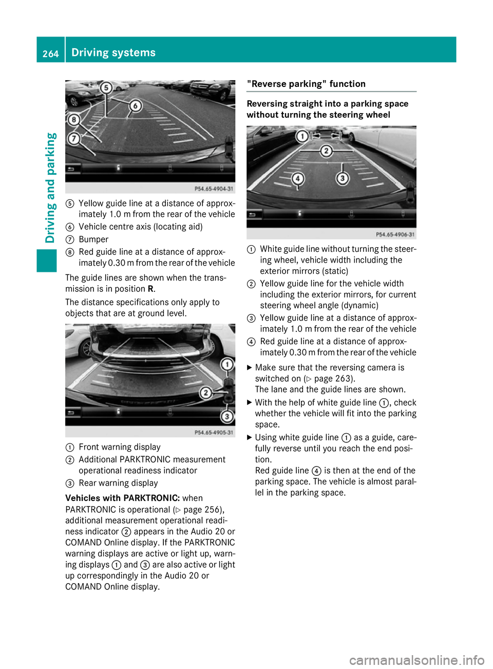
A
Yellow guide line at a distance of approx-
imately 1.0 mfrom the rear of the vehicle
B Vehicle centre axis (locating aid)
C Bumper
D Red guide line at a distance of approx-
imately 0.30 mfrom the rear of the vehicle
The guide lines are shown when the trans-
mission is in position R.
The distance specifications only apply to
objects that are at ground level. :
Front warning display
; Additional PARKTRONIC measurement
operational readiness indicator
= Rear warning display
Vehicles with PARKTRONIC: when
PARKTRONIC is operational (Y page 256),
additional measurement operational readi-
ness indicator ;appears in the Audio 20 or
COMAND Online display. If the PARKTRONIC warning displays are active or light up, warn-
ing displays :and =are also active or light
up correspondingly in the Audio 20 or
COMAND Online display. "Reverse parking" function Reversing straight into a parking space
without turning the steering wheel
:
White guide line without turning the steer-
ing wheel, vehicle width including the
exterior mirrors (static)
; Yellow guide line for the vehicle width
including the exterior mirrors, for current
steering wheel angle (dynamic)
= Yellow guide line at a distance of approx-
imately 1.0 mfrom the rear of the vehicle
? Red guide line at a distance of approx-
imately 0.30 mfrom the rear of the vehicle
X Make sure that the reversing camera is
switched on (Y page 263).
The lane and the guide lines are shown.
X With the help of white guide line :, check
whether the vehicle will fit into the parking space.
X Using white guide line :as a guide, care-
fully reverse until you reach the end posi-
tion.
Red guide line ?is then at the end of the
parking space. The vehicle is almost paral-
lel in the parking space. 264
Driving systemsDriving and parking
Page 268 of 497
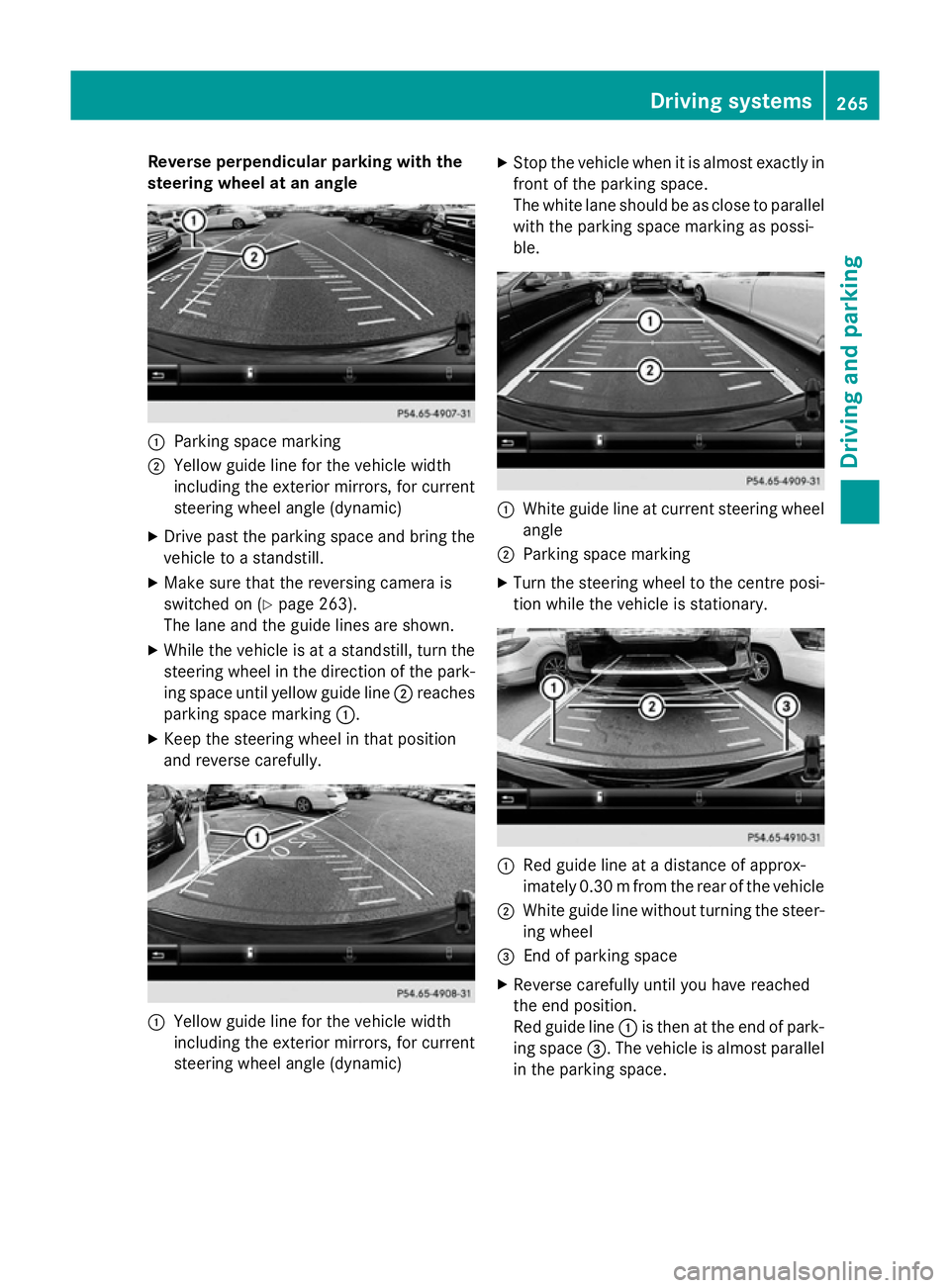
Reverse perpendicular parking with the
steering wheel at an angle :
Parking space marking
; Yellow guide line for the vehicle width
including the exterior mirrors, for current
steering wheel angle (dynamic)
X Drive past the parking space and bring the
vehicle to a standstill.
X Make sure that the reversing camera is
switched on (Y page 263).
The lane and the guide lines are shown.
X While the vehicle is at a standstill, turn the
steering wheel in the direction of the park-ing space until yellow guide line ;reaches
parking space marking :.
X Keep the steering wheel in that position
and reverse carefully. :
Yellow guide line for the vehicle width
including the exterior mirrors, for current
steering wheel angle (dynamic) X
Stop the vehicle when it is almost exactly in
front of the parking space.
The white lane should be as close to parallel
with the parking space marking as possi-
ble. :
White guide line at current steering wheel
angle
; Parking space marking
X Turn the steering wheel to the centre posi-
tion while the vehicle is stationary. :
Red guide line at a distance of approx-
imately 0.30 mfrom the rear of the vehicle
; White guide line without turning the steer-
ing wheel
= End of parking space
X Reverse carefully until you have reached
the end position.
Red guide line :is then at the end of park-
ing space =. The vehicle is almost parallel
in the parking space. Driving systems
265Driving and parking Z
Page 273 of 497
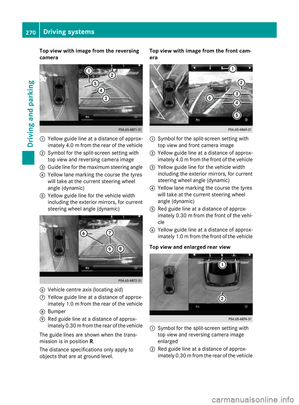
Top view with image from the reversing
camera :
Yellow guide line at a distance of approx-
imately 4.0 mfrom the rear of the vehicle
; Symbol for the split-screen setting with
top view and reversing camera image
= Guide line for the maximum steering angle
? Yellow lane marking the course the tyres
will take at the current steering wheel
angle (dynamic)
A Yellow guide line for the vehicle width
including the exterior mirrors, for current
steering wheel angle (dynamic) B
Vehicle centre axis (locating aid)
C Yellow guide line at a distance of approx-
imately 1.0 mfrom the rear of the vehicle
D Bumper
E Red guide line at a distance of approx-
imately 0.30 mfrom the rear of the vehicle
The guide lines are shown when the trans-
mission is in position R.
The distance specifications only apply to
objects that are at ground level. Top view with image from the front cam-
era
:
Symbol for the split-screen setting with
top view and front camera image
; Yellow guide line at a distance of approx-
imately 4.0 mfrom the front of the vehicle
= Yellow guide line for the vehicle width
including the exterior mirrors, for current
steering wheel angle (dynamic)
? Yellow lane marking the course the tyres
will take at the current steering wheel
angle (dynamic)
A Red guide line at a distance of approx-
imately 0.30 mfrom the front of the vehi-
cle
B Yellow guide line at a distance of approx-
imately 1.0 mfrom the front of the vehicle
Top view and enlarged rear view :
Symbol for the split-screen setting with
top view and reversing camera image
enlarged
; Red guide line at a distance of approx-
imately 0.30 mfrom the rear of the vehicle 270
Driving systemsDriving and parking
Page 274 of 497
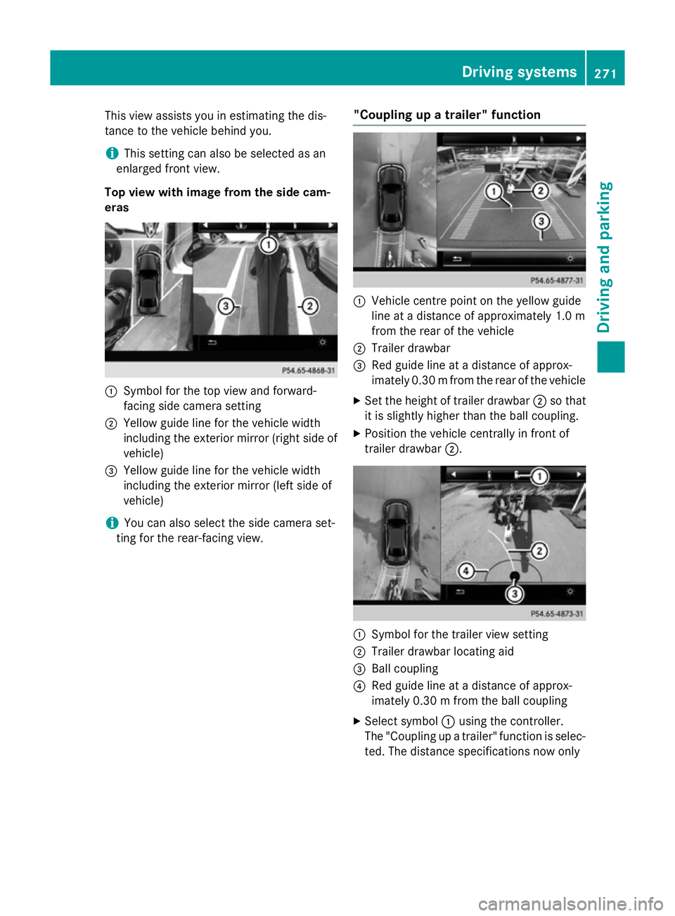
This view assists you in estimating the dis-
tance to the vehicle behind you.
i This setting can also be selected as an
enlarged front view.
Top view with image from the side cam-
eras :
Symbol for the top view and forward-
facing side camera setting
; Yellow guide line for the vehicle width
including the exterior mirror (right side of vehicle)
= Yellow guide line for the vehicle width
including the exterior mirror (left side of
vehicle)
i You can also select the side camera set-
ting for the rear-facing view. "Coupling up a trailer" function :
Vehicle centre point on the yellow guide
line at a distance of approximately 1.0 m
from the rear of the vehicle
; Trailer drawbar
= Red guide line at a distance of approx-
imately 0.30 mfrom the rear of the vehicle
X Set the height of trailer drawbar ;so that
it is slightly higher than the ball coupling.
X Position the vehicle centrally in front of
trailer drawbar ;. :
Symbol for the trailer view setting
; Trailer drawbar locating aid
= Ball coupling
? Red guide line at a distance of approx-
imately 0.30 m from the ball coupling
X Select symbol :using the controller.
The "Coupling up a trailer" function is selec- ted. The distance specifications now only Driving systems
271Driving and parking Z
Page 458 of 497
causing the unusual handling characteristics.
If you find no signs of damage, have the tyres
and wheels checked at a qualified specialist
workshop.
When parking your vehicle, make sure not to
squash the tyre sidewalls. If this cannot be
avoided, drive slowly over obstacles, e.g.
kerbs, and only at an obtuse angle. You could
otherwise damage the wheel rims and tyres. Regular checking of wheels and tyres
G
WARNING
Damaged tyres can cause tyre inflation pres-
sure loss. As a result, you could lose control of your vehicle. There is a risk of accident.
Check the tyres regularly for signs of damageand replace any damaged tyres immediately.
Check wheels and tyres for damage at least
once a month. Check wheels and tyres after
driving off-road or on rough roads. Damaged
wheels can cause a loss of tyre pressure. Pay
particular attention to damage such as:
R cuts in the tyres
R punctures
R tears in the tyres
R bulges on the tyres
R deformation or severe corrosion on wheels
Regularly check the tyre tread depth and the
condition of the tread across the whole width of the tyre (Y page 455). If necessary, turn
the front wheels to full lock in order to inspect the inner side of the tyre surface.
All wheels must have a valve cap to protect
the valve against dirt and moisture. Do not fit
anything onto the valve other than the stand-
ard valve cap or other valve caps approved for
your vehicle by Mercedes-Benz. Do not fit any other valve caps or systems, e.g. tyre pres-
sure monitoring systems.
Regularly check the pressure of all the tyres,
particularly prior to long trips. Adjust the tyre
pressure as necessary (Y page 458).Observe the notes on the emergency spare
wheel (Y page 474).
The service life of tyres depends on various
factors, including the following:
R driving style
R tyre pressure
R mileage Notes on the tyre tread
G
WARNING
Insufficient tyre tread will reduce tyre trac-
tion. The tyre is no longer able to dissipate
water. This means that on wet road surfaces, the risk of aquaplaning increases, in particularwhere speed is not adapted to suit the driving
conditions. There is a risk of accident.
If the tyre pressure is too high or too low, tyres may exhibit different levels of wear at differ-
ent locations on the tyre tread. Thus, you
should regularly check the tread depth and
the condition of the tread across the entire
width of all tyres.
Minimum tyre tread depth for:
R summer tyres: 3 mm
R M+S tyres: 4 mm
For safety reasons, replace the tyres before
the legally prescribed limit for the minimum
tyre tread depth is reached. Selecting, fitting and replacing tyres
G
WARNING
Exceeding the stated tyre load-bearing capa-
city and the approved maximum speed could
lead to tyre damage or the tyre bursting. There is a risk of accident.
Therefore, only use tyre types and sizes
approved for your vehicle model. Observe the
tyre load rating and speed rating required for your vehicle.
Pay special attention to country-specific
requirements for tyre approval. These Operation
455Wheels and tyres Z
Page 471 of 497
X
Turn the crank of the jack anti-clockwise
until the vehicle is once again standing
firmly on the ground.
X Place the jack to one side.
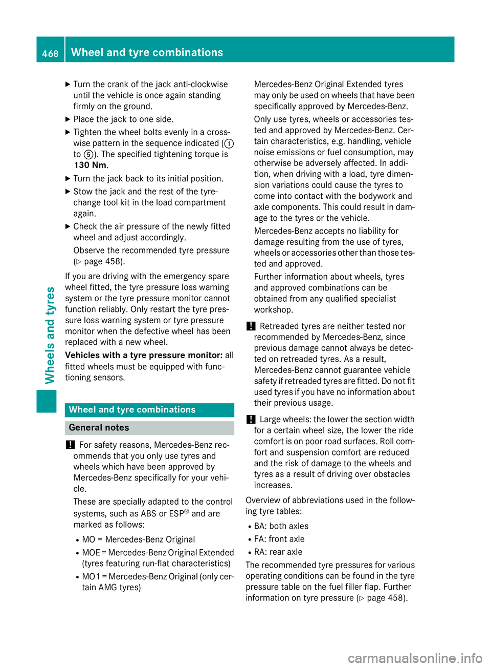
X Tighten the wheel bolts evenly in a cross-
wise pattern in the sequence indicated ( :
to A). The specified tightening torque is
130 Nm.
X Turn the jack back to its initial position.
X Stow the jack and the rest of the tyre-
change tool kit in the load compartment
again.
X Check the air pressure of the newly fitted
wheel and adjust accordingly.
Observe the recommended tyre pressure
(Y page 458).
If you are driving with the emergency spare
wheel fitted, the tyre pressure loss warning
system or the tyre pressure monitor cannot
function reliably. Only restart the tyre pres-
sure loss warning system or tyre pressure
monitor when the defective wheel has been
replaced with a new wheel.
Vehicles with a tyre pressure monitor: all
fitted wheels must be equipped with func-
tioning sensors. Wheel and tyre combinations
General notes
! For safety reasons, Mercedes-Benz rec-
ommends that you only use tyres and
wheels which have been approved by
Mercedes-Benz specifically for your vehi-
cle.
These are specially adapted to the control
systems, such as ABS or ESP ®
and are
marked as follows:
R MO = Mercedes-Benz Original
R MOE = Mercedes-Benz Original Extended
(tyres featuring run-flat characteristics)
R MO1 = Mercedes-Benz Original (only cer-
tain AMG tyres) Mercedes-Benz Original Extended tyres
may only be used on wheels that have been
specifically approved by Mercedes-Benz.
Only use tyres, wheels or accessories tes-
ted and approved by Mercedes-Benz. Cer-
tain characteristics, e.g. handling, vehicle
noise emissions or fuel consumption, may
otherwise be adversely affected. In addi-
tion, when driving with a load, tyre dimen-
sion variations could cause the tyres to
come into contact with the bodywork and
axle components. This could result in dam- age to the tyres or the vehicle.
Mercedes-Benz accepts no liability for
damage resulting from the use of tyres,
wheels or accessories other than those tes-
ted and approved.
Further information about wheels, tyres
and approved combinations can be
obtained from any qualified specialist
workshop.
! Retreaded tyres are neither tested nor
recommended by Mercedes-Benz, since
previous damage cannot always be detec-
ted on retreaded tyres. As a result,
Mercedes-Benz cannot guarantee vehicle
safety if retreaded tyres are fitted. Do not fit
used tyres if you have no information about their previous usage.
! Large wheels: the lower the section width
for a certain wheel size, the lower the ride
comfort is on poor road surfaces. Roll com-
fort and suspension comfort are reduced
and the risk of damage to the wheels and
tyres as a result of driving over obstacles
increases.
Overview of abbreviations used in the follow- ing tyre tables:
R BA: both axles
R FA: front axle
R RA: rear axle
The recommended tyre pressures for various
operating conditions can be found in the tyre pressure table on the fuel filler flap. Further
information on tyre pressure (Y page 458).468
Wheel and tyre combinationsWheels and tyres
Page 491 of 497
!
Only the washer fluids SummerFit and
WinterFit can be mixed. Otherwise, the
spraying nozzles could become blocked.
Comply with the important safety notes for
service products when handling washer fluid
(Y page 480).
At temperatures above freezing:
X Fill the washer fluid reservoir with a mixture
of water and washer fluid, e.g. MB Sum-
merFit.
Mix 1 part MB SummerFit to 100 parts water.
At temperatures below freezing:
X Fill the washer fluid reservoir with a mixture
of water and washer fluid, e.g. MB Winter-
Fit.
For the correct mixing ratio refer to the
information on the antifreeze reservoir.
i Add washer fluid concentrate, e.g. MB
SummerFit or MB WinterFit, to the washer
fluid all year round. Vehicle data
General notes
Please note that for the specified vehicle
data: R the heights specified may vary as a result
of:
- tyres
- load
- condition of the suspension
- optional equipment
R optional equipment reduces the maximum
payload
R Vehicle-specific weight information can be
found on the vehicle identification plate
(Y page 480).
R only for certain countries: you can find vehi-
cle-specific vehicle data in the COC docu-
ments (CERTIFICATE OF CONFORMITY).
These documents are delivered with your
vehicle. Observe the information relating to level con-
trol:
R AIR BODY CONTROL (Y page 252)
R Off-Road Engineering package
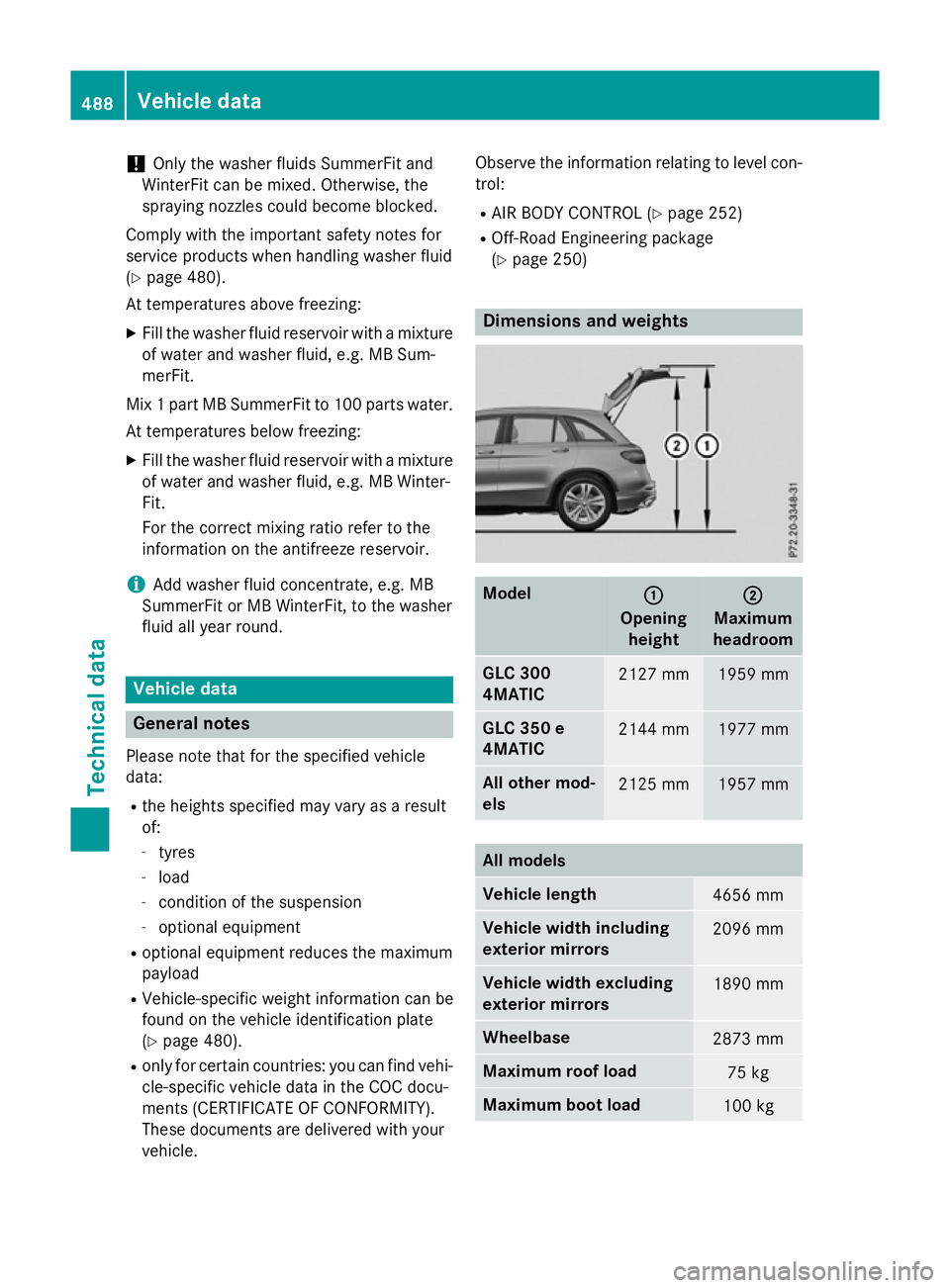
(Y page 250) Dimensions and weights
Model
: :
Opening height ;
;
Maximum
headroom GLC 300
4MATIC
2127 mm 1959 mm
GLC 350 e
4MATIC
2144 mm 1977 mm
All other mod-
els
2125 mm 1957 mm
All models
Vehicle length
4656 mm
Vehicle width including
exterior mirrors
2096 mm
Vehicle width excluding
exterior mirrors
1890 mm
Wheelbase
2873 mm
Maximum roof load
75 kg
Maximum boot load
100 kg488
Vehicle dataTechnical data