180 W MERCEDES-BENZ GLE 2016 Owners Manual
[x] Cancel search | Manufacturer: MERCEDES-BENZ, Model Year: 2016, Model line: GLE, Model: MERCEDES-BENZ GLE 2016Pages: 450, PDF Size: 12.92 MB
Page 182 of 450
The function of the electric parking brake is
dependent on the on-board voltage. If the on-
board voltage is low or there is a malfunction in
the system, it may not be possible to apply the
released parking brake. X
If this is the case, only park the vehicle on
level ground and secure it to prevent it rolling
away. X
Shift the automatic transmission to position
P .
It may not be possible to release an applied
parking brake if the on-board voltage is low or
there is a malfunction in the system. Contact a
qualified specialist workshop.
i The electric parking brake performs a func-
tion test at regular intervals while the engine
is switched off. The sounds that can be heard
while this is occurring are normal.
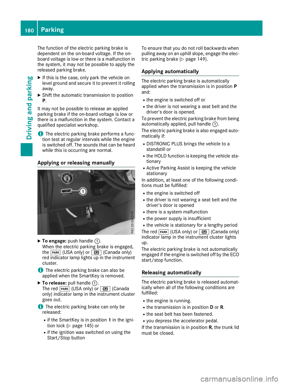
Applying or releasing manually
X
To engage: push handle C .
When the electric parking brake is engaged,
the I (USA only) or $ (Canada only)
red indicator lamp lights up in the instrument
cluster.
i The electric parking brake can also be
applied when the SmartKey is removed. X
To release: pull handle C .
The red I (USA only) or $ (Canada
only) indicator lamp in the instrument cluster
goes out.
i The electric parking brake can only be
released: R
if the SmartKey is in position 1 in the igni-
tion lock ( Y
page 145) orR
if the ignition was switched on using the
Start/Stop button To ensure that you do not roll backwards when
pulling away on an uphill slope, engage the elec-
tric parking brake ( Y
page 149).
Applying automatically The electric parking brake is automatically
applied when the transmission is in position P
and: R
the engine is switched off or R
the driver is not wearing a seat belt and the
driver's door is opened.
To prevent the electric parking brake from being
automatically applied, pull handle C .
The electric parking brake is also engaged auto-
matically if: R
DISTRONIC PLUS brings the vehicle to a
standstill or R
the HOLD function is keeping the vehicle sta-
tionary R
Active Parking Assist is keeping the vehicle
stationary
In addition, at least one of the following condi-
tions must be fulfilled: R
the engine is switched off R
the driver is not wearing a seat belt and the
driver's door is opened R
there is a system malfunction R
the power supply is insufficient R
the vehicle is stationary for a lengthy period
The red I (USA only) or $ (Canada only)
indicator lamp in the instrument cluster lights
up.
The electric parking brake is not automatically
engaged if the engine is switched off by the ECO
start/stop function.
Releasing automatically The electric parking brake is released automat-
ically when all of the following conditions are
fulfilled: R
the engine is running. R
the transmission is in position D or R .R
the seat belt has been fastened. R
you depress the accelerator pedal.
If the transmission is in position R , the trunk lid
must be closed.180
Parking
Driving and parking
Page 208 of 450
Make sure no one is underneath the vehicle or
in the immediate vicinity of the wheel arches
when the vehicle is being lowered.
If you unlock the vehicle or open a door, the
vehicle begins to compensate for load discrep-
ancies while still parked. However, for signifi-
cant level changes, such as after the vehicle has
been stationary for a long period, the engine
must be on. For safety reasons, the vehicle is
only lowered when the doors are closed. Low-
ering is interrupted if a door is opened, and it
continues once the door has been closed.
ADS and ADS PLUS (Adaptive Damping
System) General notes The Adaptive Damping System automatically
controls the calibration of the dampers. The
damping characteristics adapt to the current
operating and driving situation.
The damping is tuned individually to each wheel
and depends on: R
your driving style, e.g. sporty R
the road surface conditions R
the drive program selected R
the vehicle level setting
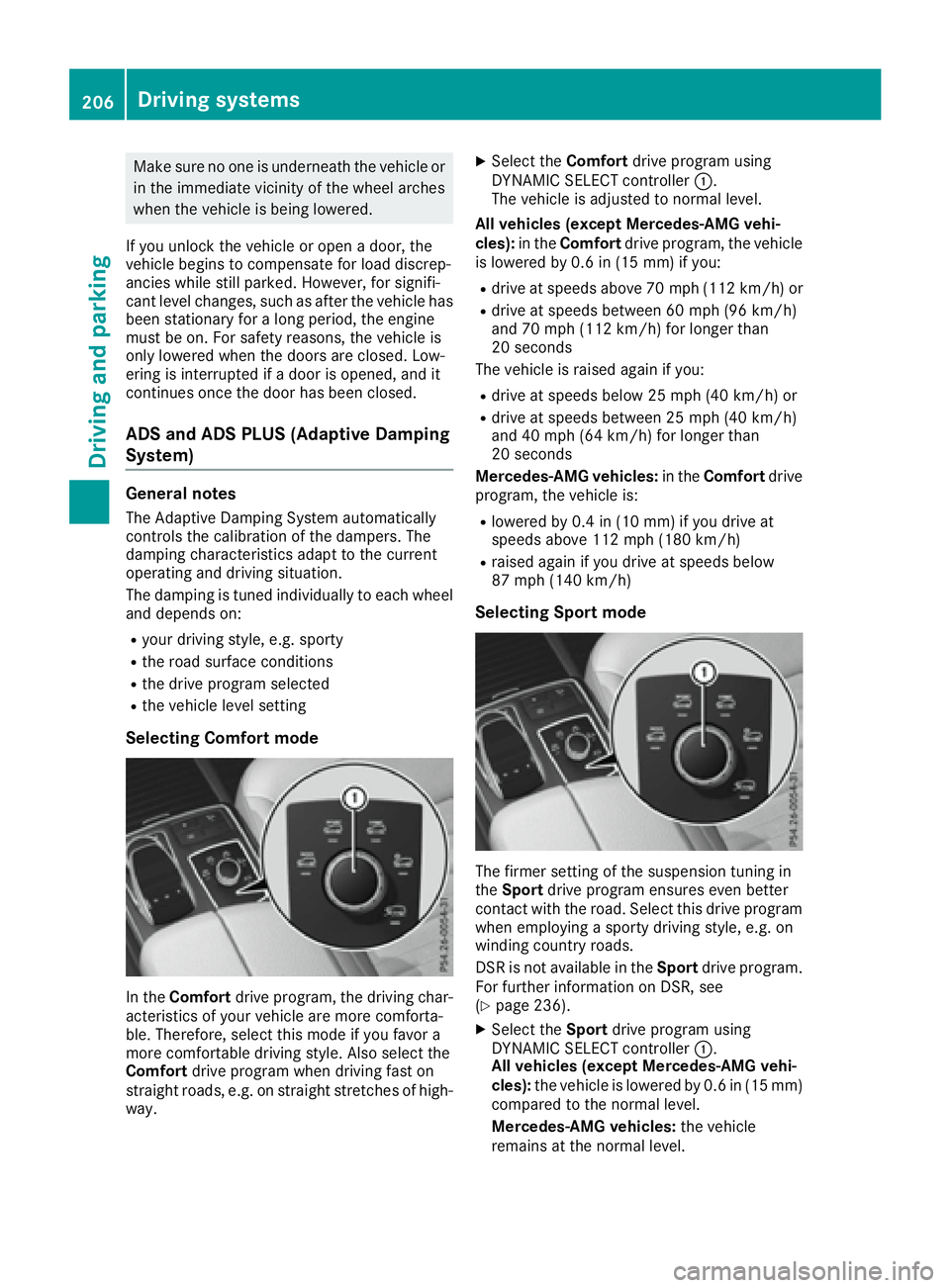
Selecting Comfort mode
In the Comfort drive program, the driving char-
acteristics of your vehicle are more comforta-
ble. Therefore, select this mode if you favor a
more comfortable driving style. Also select the
Comfort drive program when driving fast on
straight roads, e.g. on straight stretches of high-
way. X
Select the Comfort drive program using
DYNAMIC SELECT controller C .
The vehicle is adjusted to normal level.
All vehicles (except Mercedes-AMG vehi-
cles): in the Comfort drive program, the vehicle
is lowered by 0.6 in (15 mm) if you: R
drive at speeds above 70 mph (112 km/h) or R
drive at speeds between 60 mph (96 km/h)
and 70 mph (112 km/h) for longer than
20 seconds
The vehicle is raised again if you: R
drive at speeds below 25 mph (40 km/h) or R
drive at speeds between 25 mph (40 km/h)
and 40 mph (64 km/h) for longer than
20 seconds
Mercedes-AMG vehicles: in the Comfort drive
program, the vehicle is: R
lowered by 0.4 in (10 mm) if you drive at
speeds above 112 mph (180 km/h) R
raised again if you drive at speeds below
87 mph (140 km/h)
Selecting Sport mode
The firmer setting of the suspension tuning in
the Sport drive program ensures even better
contact with the road. Select this drive program
when employing a sporty driving style, e.g. on
winding country roads.
DSR is not available in the Sport drive program.
For further information on DSR, see
( Y
page 236). X
Select the Sport drive program using
DYNAMIC SELECT controller C .
All vehicles (except Mercedes-AMG vehi-
cles): the vehicle is lowered by 0.6 in (15 mm)
compared to the normal level.
Mercedes-AMG vehicles: the vehicle
remains at the normal level.206
Driving systems
Driving and parking
Page 264 of 450

the vehicle and trailer may carry, pay atten-
tion to the respective lowest values. R
The trailer drawbar load on the ball coupling
must be added to the rear axle load to avoid
exceeding the permissible gross axle weight.
The permissible gross vehicle weight is indi-
cated on the identification plate located on
the B-pillar on the driver's side of the vehicle.
i Mercedes-Benz recommends a trailer load
where the trailer drawbar noseweight
accounts for 8 % to 15 % of the trailer's per-
missible gross weight.
i The weight of additional accessories, pas-
sengers, and cargo reduces the permissible
trailer load and drawbar load for your vehicle.
Checking the vehicle and trailer weight R
To check that the weights of the towing vehi-
cle and the trailer comply with the maximum
permissible values, have the vehicle/trailer
combination (including the driver, passen-
gers, and cargo with a fully laden trailer)
weighed on a calibrated weighbridge. R
Check the gross axle weight rating of the front
and rear axles, the gross weight of the trailer
and the trailer drawbar noseweight.
Removing the ball coupling X
Remove the spring cotter. X
Remove the bolt from the ball coupling
recess. X
Remove the ball coupling from the ball cou-
pling recess. X
Clean the ball coupling if it is dirty. X
Stow the ball coupling so that it cannot be
thrown around.
Observe the loading guidelines ( Y
page 329)
and the safety notes regarding stowage spaces
( Y
page 330).
Information on cleaning and care of the trailer
tow hitch ( Y
page 366).
Trailer power supply
! Accessories with a maximum power con-
sumption of 180 W can be connected to the
permanent power supply. You must not charge a trailer battery using the
power supply.
The trailer socket of your vehicle is equipped at
the factory with a permanent power supply.
The permanent power supply is supplied via
trailer socket pin 4.
The trailer's permanent power supply is
switched off in the event of low vehicle supply
voltage and after six hours at the latest.
A qualified specialist workshop can provide
more information about installing the trailer
electrics.262
Towing a trailer
Driving an d parking
Page 345 of 450
12 V sockets
General notes X
Turn the SmartKey to position 1 in the ignition
lock ( Y
page 145).
With the exception of the socket in the front
center console, all sockets can be used for
accessories with a maximum current draw of
240 W (20 A). The socket in the front center
console can be used for accessories with a max-
imum current draw of 180 W( 15 A). Accessories
include such items as chargers for mobile
phones.
If you use the sockets for long periods when the
engine is switched off, the battery may dis-
charge.
i An emergency cut-out ensures that the on-
board voltage does not drop too low. If the on-
board voltage is too low, the power to the
sockets is automatically cut. This ensures
that there is sufficient power to start the
engine.
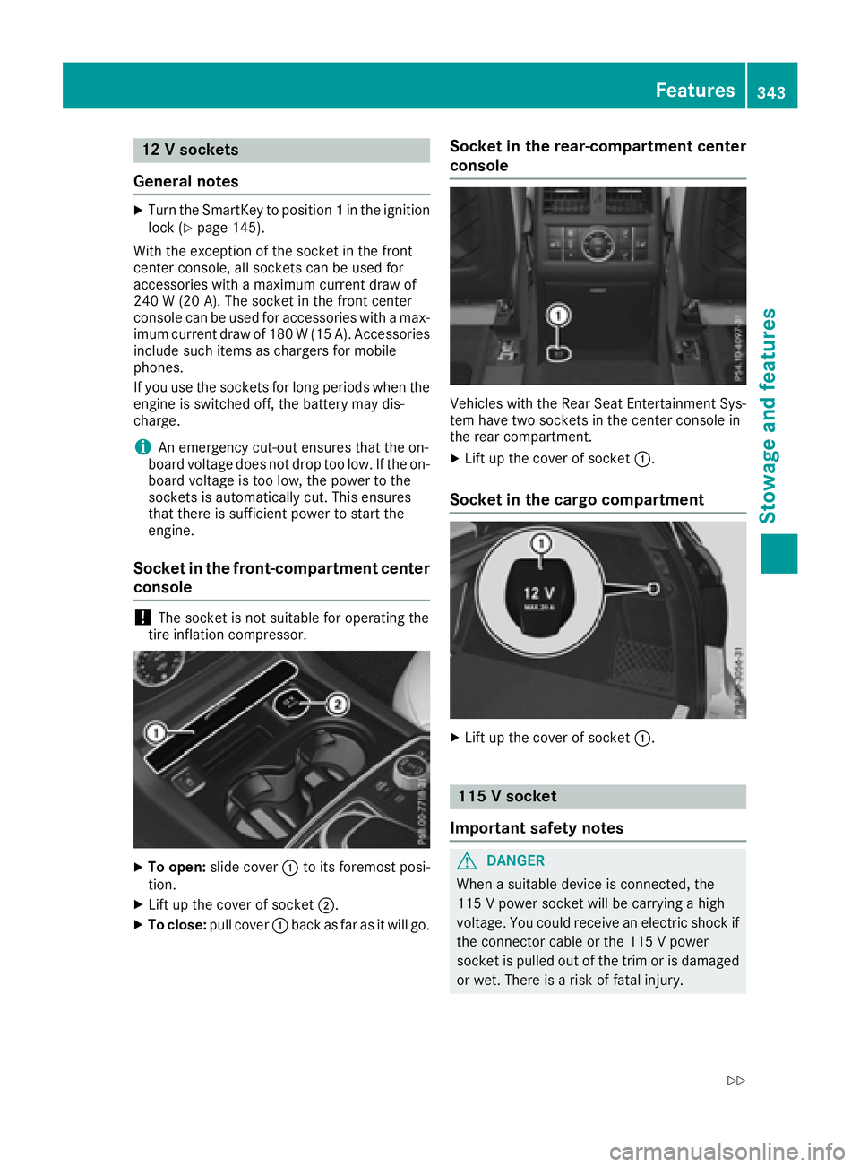
Socket in the front-compartment center
console
! The socket is not suitable for operating the
tire inflation compressor.
X
To open: slide cover C to its foremost posi-
tion. X
Lift up the cover of socket D .X
To close: pull cover C back as far as it will go. Socket in the rear-compartment center
console
Vehicles with the Rear Seat Entertainment Sys-
tem have two sockets in the center console in
the rear compartment. X
Lift up the cover of socket C .
Socket in the cargo compartment
X
Lift up the cover of socket C .
115 V socket
Important safety notes
G DANGER
When a suitable device is connected, the
115 V powe r socket will be carrying a high
voltage. You could receive an electric shock if
the connector cable or the 115 V power
socket is pulled out of the trim or is damaged
or wet. There is a risk of fatal injury. Features 343
Stowage and features Z
Page 375 of 450
Do not switch off th e tire inflation com -
pressor during this phase .X
Let th e tire inflation compressor run for a
maximum of fiv e minutes. The tire should then
hav e attained a pressur e of at least 18 0 kP a
(1. 8 bar/2 6 psi) .
If a pressur e of 18 0 kP a (1. 8 bar/26 psi) has
been attained after fiv e minutes, see "Tir e pres-
sur e reached" ( Y
page 373).
If a tire pressur e of 18 0 kP a( 1.8 bar/26 psi) has
not been attained after five minutes, see "Tire
pressure not reached" ( Y
page 373).
If tire sealant has escaped, clean it off affected
areas as quickly as possible. Use plain water if
possible.
If your clothes are soiled with tire sealant, have
them cleaned with perchloroethylene at a dry
cleaner as soon as possible.
Tire pressure not reached If a pressure of 180 kPa (1.8 bar/26 psi) has not
been attained after five minutes: X
Switch off the tire inflation compressor. X
Unscrew the filler hose from the valve of the
faulty tire.
Note that tire sealant may escape when you
unscrew the filler hose. X
Very slowly drive forwards or reverse approx-
imately 30 ft (10 m). X
Pump up the tire again.
After a maximum of five minutes the tire pres-
sure must be at least 180 kPa (1.8 bar/
26 psi).
G WARNING
If the required tire pressure is not reached
after the specified time, the tire is too badly
damaged. The tire sealant cannot repair the
tire in this instance. Damaged tires and a tire
pressure that is too low can significantly
impair the vehicle's braking and driving char-
acteristics. There is a risk of accident.
Do not continue driving. Contact a qualified
specialist workshop. Tire pressure reached
G WARNING
A tire temporarily sealed with tire sealant
impairs the driving characteristics and is not
suitable for higher speeds. There is a risk of
accident.
You should therefore adapt your driving style
accordingly and drive carefully. Do not exceed
the specified maximum speed with a tire that
has been repaired using tire sealant.
The maximum permissible speed for a tire
sealed with tire sealant is 50 mph (80 km/h).
The upper part of the TIREFIT sticker must be
affixed to the instrument cluster in the driver's
field of vision.
! Residue from the tire sealant may come out
of the filler hose after use. This could cause
stains.
Therefore, place the filler hose in the plastic
bag which contained the TIREFIT kit.
H Environmental note
Have the used tire sealant bottle disposed of
professionally, e.g. at a qualified specialist
workshop.
If a tire pressure of 180 kPa (1.8 bar/26 psi) has
been attained after five minutes: X
Switch off the tire inflation compressor. X
Unscrew the filler hose from the valve of the
faulty tire. X
Stow the tire sealant bottle and the tire infla-
tion compressor. X
Pull away immediately .X
Stop after driving for approximately ten
minutes and check the tire pressure with the
tire inflation compressor.
The tire pressure must now be at least
130 kPa (1.3 bar/19 psi).
G WARNING
If the required tire pressure is not reached
after driving for a short period, the tire is too
badly damaged. The tire sealant cannot repair
the tire in this instance. Damaged tires and a
tire pressure that is too low can significantly Flat tire 373
Breakdown assitance Z
Page 402 of 450
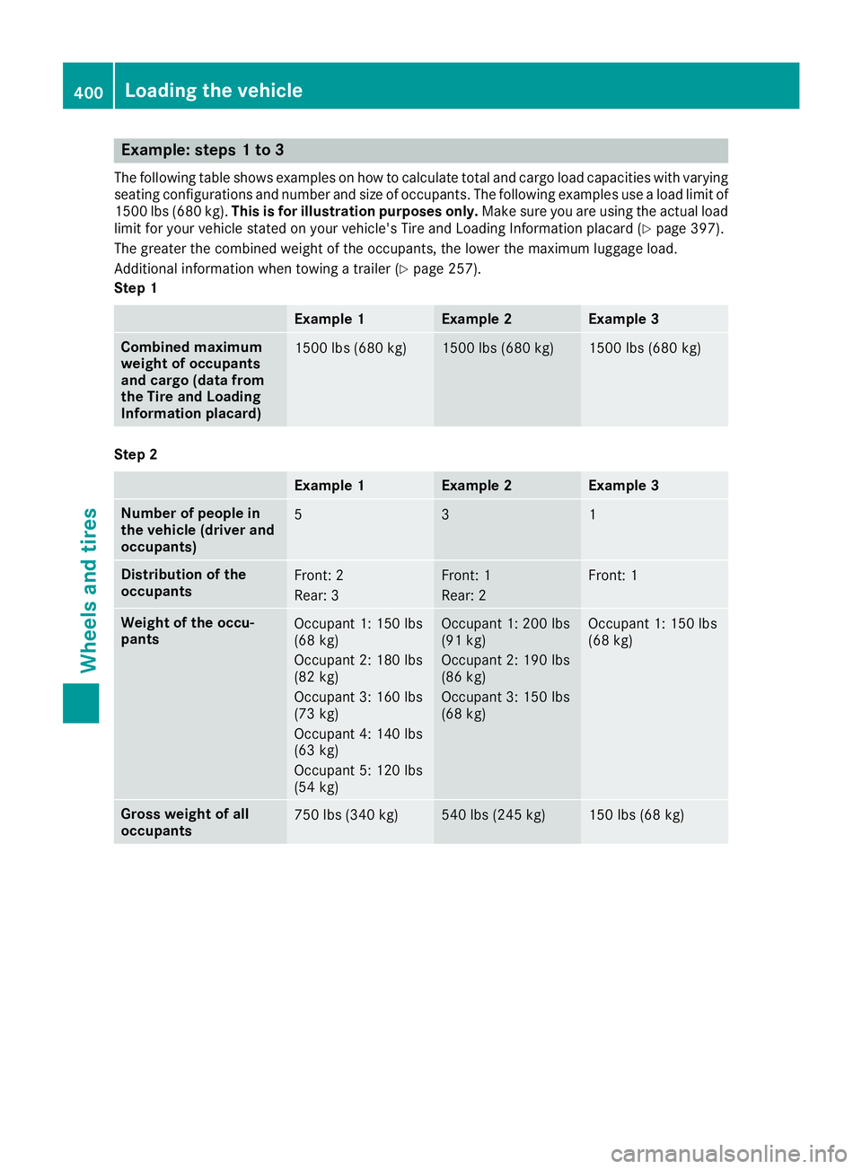
Example: steps 1 to 3 The following table shows examples on how to calculate total and cargo load capacities with varying
seating configurations and number and size of occupants. The following examples use a load limit of
1500 lbs (680 kg). This is for illustration purposes only. Make sure you are using the actual load
limit for your vehicle stated on your vehicle's Tire and Loading Information placard ( Y
page 397).
The greater the combined weight of the occupants, the lower the maximum luggage load.
Additional information when towing a trailer ( Y
page 257).
Step 1
Example 1 Example 2 Example 3
Combined maximum
weight of occupants
and cargo (data from
the Tire and Loading
Information placard) 1500 lbs (680 kg) 1500 lbs (680 kg) 1500 lbs (680 kg)
Step 2
Example 1 Example 2 Example 3
Number of people in
the vehicle (driver and
occupants) 5 3 1
Distribution of the
occupants Front: 2
Rear: 3 Front: 1
Rear: 2 Front: 1
Weight of the occu-
pants Occupant 1: 150 lbs
(68 kg)
Occupant 2: 180 lbs
(82 kg)
Occupant 3: 160 lbs
(73 kg)
Occupant 4: 140 lbs
(63 kg)
Occupant 5: 120 lbs
(54 kg) Occupant 1: 200 lbs
(91 kg)
Occupant 2: 190 lbs
(86 kg)
Occupant 3: 150 lbs
(68 kg) Occupant 1: 150 lbs
(68 kg)
Gross weight of all
occupants 750 lbs (340 kg) 540 lbs (245 kg) 150 lbs (68 kg)400
Loading the vehicle
Wheels and tires
Page 444 of 450
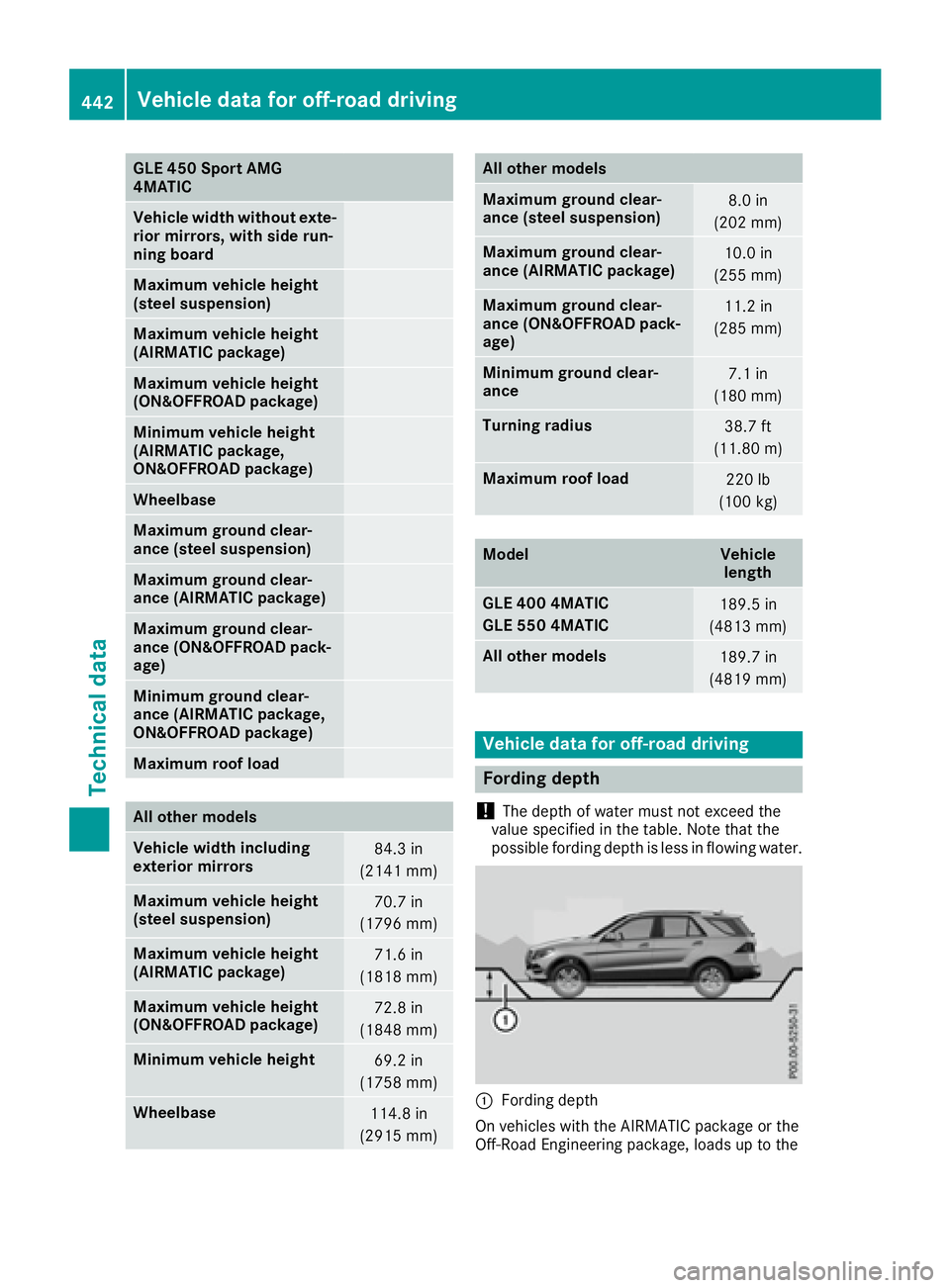
GLE 450 Sport AMG
4MATIC
Vehicle width without exte-
rior mirrors, with side run-
ning board
Maximum vehicle height
(steel suspension)
Maximum vehicle height
(AIRMATIC package)
Maximum vehicle height
(ON&OFFROAD package)
Minimum vehicle height
(AIRMATIC package,
ON&OFFROAD package)
Wheelbase
Maximum ground clear-
ance (steel suspension)
Maximum ground clear-
ance (AIRMATIC package)
Maximum ground clear-
ance (ON&OFFROAD pack-
age)
Minimum ground clear-
ance (AIRMATIC package,
ON&OFFROAD package)
Maximum roof load
All other models
Vehicle width including
exterior mirrors 84.3 in
(2141 mm)
Maximum vehicle height
(steel suspension) 70.7 in
(1796 mm)
Maximum vehicle height
(AIRMATIC package) 71.6 in
(1818 mm)
Maximum vehicle height
(ON&OFFROAD package) 72.8 in
(1848 mm)
Minimum vehicle height
69.2 in
(1758 mm)
Wheelbase
114.8 in
(2915 mm) All other models
Maximum ground clear-
ance (steel suspension) 8.0 in
(202 mm)
Maximum ground clear-
ance (AIRMATIC package) 10.0 in
(255 mm)
Maximum ground clear-
ance (ON&OFFROAD pack-
age) 11.2 in
(285 mm)
Minimum ground clear-
ance 7.1 in
(180 mm)
Turning radius
38.7 ft
(11.80 m)
Maximum roof load
220 lb
(100 kg)
Model Vehicle
length
GLE 400 4MATIC
GLE 550 4MATIC 189.5 in
(4813 mm)
All other models
189.7 in
(4819 mm)
Vehicle data for off-road driving
Fording depth
! The depth of water must not exceed the
value specified in the table. Note that the
possible fording depth is less in flowing water.
C
Fording depth
On vehicles with the AIRMATIC package or the
Off-Road Engineering package, loads up to the442
Vehicle data for off-road driving
Technical data