door lock MERCEDES-BENZ GLE 2017 Service Manual
[x] Cancel search | Manufacturer: MERCEDES-BENZ, Model Year: 2017, Model line: GLE, Model: MERCEDES-BENZ GLE 2017Pages: 390, PDF Size: 11.63 MB
Page 329 of 390
X
Vehicles with the AIRMATIC package:
make sure that the normal vehicle level is
selected ( Y
page 182).X
Vehicles with the Off-Road Engineering
package: make sure that the normal vehicle
level is selected ( Y
page 176).X
Switch off the engine. X
Vehicles without KEYLESS-GO: remove the
SmartKey from the ignition lock. X
Vehicles with KEYLESS-GO: open the driv-
er's door.
The on-board electronics now have status 0 .
This is the same as the SmartKey having been
removed. X
Vehicles with KEYLESS-GO: remove the
Start/Stop button from the ignition lock
( Y
page 132). X
Make sure that the engine cannot be started
via your smartphone ( Y
page 134).X
Make sure that the passengers are not endan-
gered as they do so. Make sure that no one is
near the danger area while a wheel is being
changed. Anyone who is not directly assisting
in the wheel change should, for example,
stand behind the barrier. X
Get out of the vehicle. Pay attention to traffic
conditions when doing so. X
Close the driver's door. X
Unload heavy luggage.
i Only operate the tire inflation compressor
using a 12 V socket, even if the ignition is
turned off ( Y
page 301).
An emergency cut-out ensures that the on-
board voltage does not drop too low. If the on-
board voltage is too low , the power to the
so ckets is automatically cut. This ensures
that there is sufficient power to start the
engine.
MOExtended tires (tires with run-flat
properties)
General notes
With MOExtended tires (tires with run flat char-
acteristics), you can continue to drive your vehi-
cle even if there is a total loss of pressure in one
or more tires. The affected tire must not show
any clearly visible damage.
You can recognize MOExtended tires by the
MOExtended marking which appears on the sidewall of the tire. You will find this marking
next to the tire size designation, the load-bear-
ing capacity and the speed index ( Y
page 356).
MOExtended tires may only be used in conjunc-
tion with an active tire pressure loss warning
system or with an active tire pressure monitor.
If a pressure loss warning message appears
in the multifunction display: R
observe the instructions in the display mes-
sages ( Y
page 262). R
check the tire for damage. R
if driving on, observe the following notes.
The driving distance possible in run-flat mode is
approximately 50 miles (80 km) when the vehi-
cle is partially laden and approximately 18 miles
(30 km) when the vehicle is fully laden.
In addition to the vehicle load, the driving dis-
tance possible depends upon: R
vehicle speed R
road condition R
outside temperature
The driving distance possible in run-flat mode
may be reduced by extreme driving conditions
or maneuvers, or it can be increased through a
moderate style of driving.
The driving dista nce possible in run-flat mode is
counte
d from the moment the tire pressure loss
warning appears in the multifunction display.
You must not exceed a maximum speed of
50 mph (80 km/h).
i When replacing one or all tires, please
observe the following specifications for your
vehicle's tires: R
size R
type and R
the "MOExtended" mark
If a tire has gone flat and cannot be replaced
with a MOExtended tire, a standard tire may
be used as a temporary measure. Make sure
that you use the proper size and type (sum-
mer or winter tire).
i Vehicles equipped with MOExtended tires
are not equipped with a TIREFIT kit at the fac-
tory. It is therefore recommended that you
additionally equip your vehicle with a TIREFIT
kit if you mount tires that do not feature run-
flat properties, e.g. winter tires. A TIREFIT kit
may be obtained from a qualified specialist
workshop. Flat tire 327
Breakdown assistance
Page 339 of 390
shift to position P when the driver's or front-
passenger door are opened, which could lead
to damage to the transmission.
! Do not tow with sling-type equipment. This
could damage the vehicle.
! Vehicles with differential locks: make sure
the differential locks are in automatic mode.
When towing, the differential locks must not
be switched on. The transmission may other-
wise be damaged.
! The vehicle can be towed a maximum of
30 miles (50km). The towing speed of 30 mph
(50 km/h) must not be exceeded.
If the vehicle has to be towed more than
30 miles (50km), the entire vehicle must be
raised and transported.
It is better to have the vehicle transported than
to have it towed away.
If the vehicle has suffered transmission damage,
have it transported on a transporter or trailer.
The automatic transmission must be in position
N when the vehicle is being towed.
The battery must be connected and charged.
Otherwise, you: R
cannot turn the SmartKey to position 2 in the
ignition lock R
cannot release the electric parking brake R
cannot shift the automatic transmission to
position N
Disarm the automatic locking feature before the
vehicle is towed ( Y
page 233). You could other-
wise be locked out when pushing or towing the
vehicle.
If the vehicle is in a dangerous area, it can be
towed out of that area with both axles on the
ground. In this case, the towing distance must
not be greater than 165 ft (50 m) and must not
exceed a towing speed of 6 mph (10 km/h). For
longer distances, have the vehicle loaded and
transported. Installing/removing the towing eye
Installing the towing eye
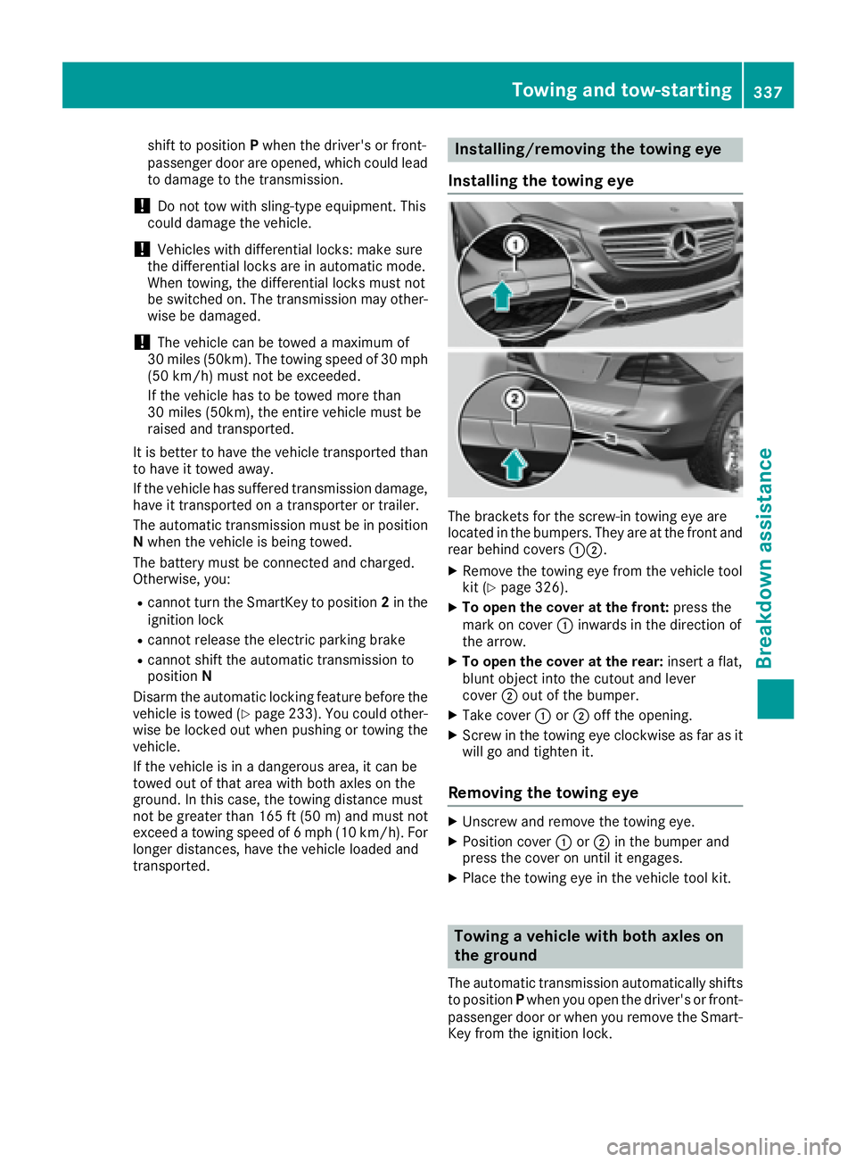
The brackets for the screw-in towing eye are
located in the bumpers. They are at the front and
rear behind covers CD .X
Remove the towing eye from the vehicle tool
kit ( Y
page 326). X
To open the cover at the front: press the
mark on cover C inwards in the direction of
the arrow. X
To open the cover at the rear: insert a flat,
blunt object into the cutout and lever
cover D out of the bumper. X
Take cover C or D off the opening.X
Screw in the towing eye clockwise as far as it
will go and tighten it.
Removing the towing eye X
Unscrew and remove the towing eye. X
Position cover C or D in the bumper and
press the cover on until it engages. X
Place the towing eye in the vehicle tool kit.
Towing a vehicle with both axles on
the ground
The automatic transmission automatically shifts
to position P when you open the driver's or front-
passenger door or when you remove the Smart-
Key from the ignition lock.Towing and tow-starting 337
Breakdown assistance Z
Page 341 of 390
You can find information on "Jump-starting"
under ( Y
page 333).
Fuses
Important safety notes
G WARNING
If you manipulate or bridge a faulty fuse or if
you replace it with a fuse with a higher amper-
age, the electric cables could be overloaded.
This could result in a fire. There is a risk of an
accident and injury.
Always replace faulty fuses with the specified
new fuses having the correct amperage.
! For the fuse boxes in the engine compart-
ment and under the rear bench seat, only use
fuses with the suffix "S". Otherwise, compo-
nents or systems could be damaged.
! Make sure that no moisture can enter the
fuse box when the cover is open.
! When closing the cover, make sure that it is
lying correctly on the fuse box. Moisture seep-
ing in or dirt could otherwise impair the oper-
ation of the fuses.
The fuses in your vehicle serve to close down
faulty circuits. If a fuse blows, all the compo-
nents on the circuit and their functions stop
operating.
Blown fuses must be replaced with fuses of the
same rating, which you can recognize by the
color and value. The fuse ratings are listed in the
fuse allocation chart.
The fuse allocation chart is located in the fuse
box under the rear bench seat ( Y
page 340).
If a newly inserted fuse also blows, have the
cause traced and rectified at a qualified special-
ist workshop, e.g. an authorized Mercedes-Benz
Center.
Before changing a fuse
Observe the important safety notes
( Y
page 339) X
Switch off the engine. X
Switch off all electrical consumers. X
Remove the SmartKey from the ignition lock.
or, in vehicles with KEYLESS-GO start-function
or KEYLESS ‑ GO X
Open the driver's door.
The vehicle electronics now have status 0 .
This is the same as the SmartKey having been
removed.
The driver’s door can be closed again. X
Secure the vehicle against rolling away
( Y
page 153).
All indicator lamps in the instrument cluster
must be off.
The fuses are located in various fuse boxes: R
Fuse box on the front-passenger side of the
dashboard R
Fuse box in the engine compartment on the
right-hand side of the vehicle, when viewed in
the direction of travel R
Fuse box under the rear bench seat
Dashboard fuse box
! Do not use a pointed object such as a screw-
driver to open the cover in the dashboard. You
could damage the dashboard or the cover.
Mercedes-Benz recommends that you have this
work performed at a qualified specialist work-
shop, e.g. at an authorized Mercedes-Benz Cen-
ter.
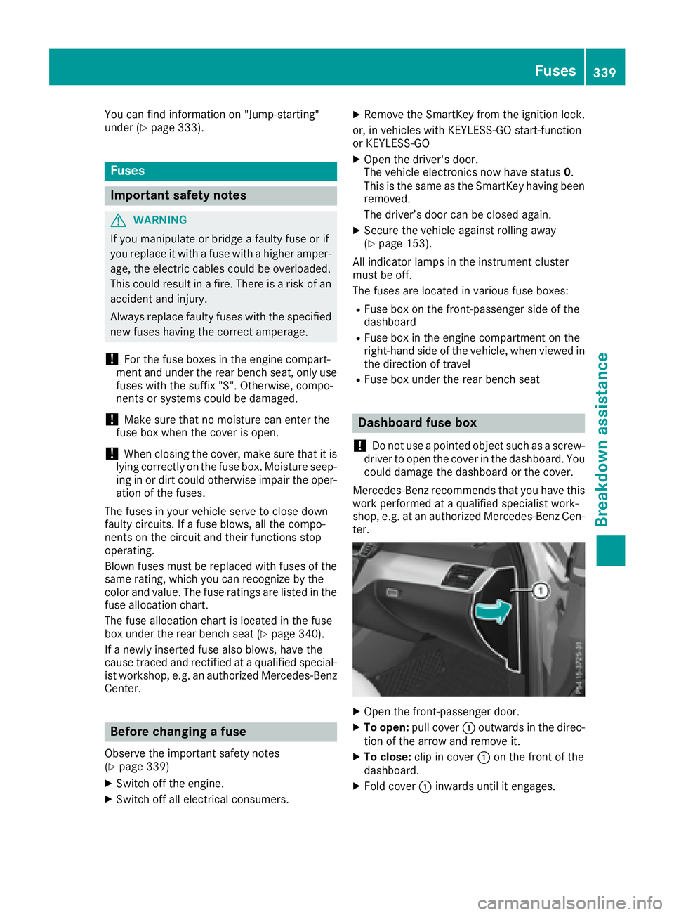
X
Open the front-passenger door. X
To open: pull cover C outwards in the direc-
tion of the arrow and remove it. X
To close: clip in cover C on the front of the
dashboard. X
Fold cover C inwards until it engages.Fuses 339
Breakdown assistance Z
Page 364 of 390
be required earlier. Do not change the direction
of wheel rotation.
Clean the contact surfaces of the wheel and the
brake disc thoroughly every time a wheel is rota-
ted. Check the tire pressure and, if necessary,
restart the tire pressure loss warning system or
the tire pressure monitor ( Y
page 348).
Direction of rotation Tires with a specified direction of rotation have
additional benefits, e.g. if there is a risk of hydro-
planing. These advantages can only be gained if
the tires are installed corresponding to the
direction of rotation.
An arrow on the sidewall of the tire indicates its
correct direction of rotation.
Storing wheels Store wheels that are not being used in a cool,
dry and preferably dark place. Protect the tires
from oil, grease, gasoline and diesel.
Mounting a wheel
Preparing the vehicle X
Vehicle with emergency spare wheel:
when mounting the emergency spare wheel in
the event of a flat tire, follow the additional
notes on vehicle preparation under "Flat tire"
( Y
page 326).X
Stop the vehicle on solid, non-slippery and
level ground. X
Apply the electric parking brake manually. X
Bring the front wheels into the straight-ahead
position. X
Vehicles with automatic transmission:
shift the automatic transmission to position
P . X
Vehicles with the AIRMATIC package:
make sure that the normal vehicle level is
selected ( Y
page 182).X
Vehicles with the Off-Road Engineering
package: make sure that the normal vehicle
level is selected ( Y
page 176).X
Switch off the engine. X
Vehicles without KEYLESS-GO: remove the
SmartKey from the ignition lock. X
Vehicles with KEYLESS-GO: open the driv-
er's door.
The on-board electronics now have status 0 .
This is the same as the SmartKey having been
removed. X
Vehicles with KEYLESS-GO: remove the
Start/Stop button from the ignition lock
( Y
page 132). X
Make sure that the engine cannot be started
via your smartphone ( Y
page 134).X
If included in the vehicle equipment, remove
the tire-change tool kit from the vehicle. X
Safeguard the vehicle against rolling away.
i Apart from certain country-specific varia-
tions, vehicles are not equipped with a tire-
change tool kit. For information on which
tools are required to perform a wheel change
on your vehicle, consult an authorized
Mercedes-Benz Center.
Necessary tire-changing tools can include, for
example: R
Jack R
Wheel chock R
Lug wrench
Securing the vehicle to prevent it from
rolling away
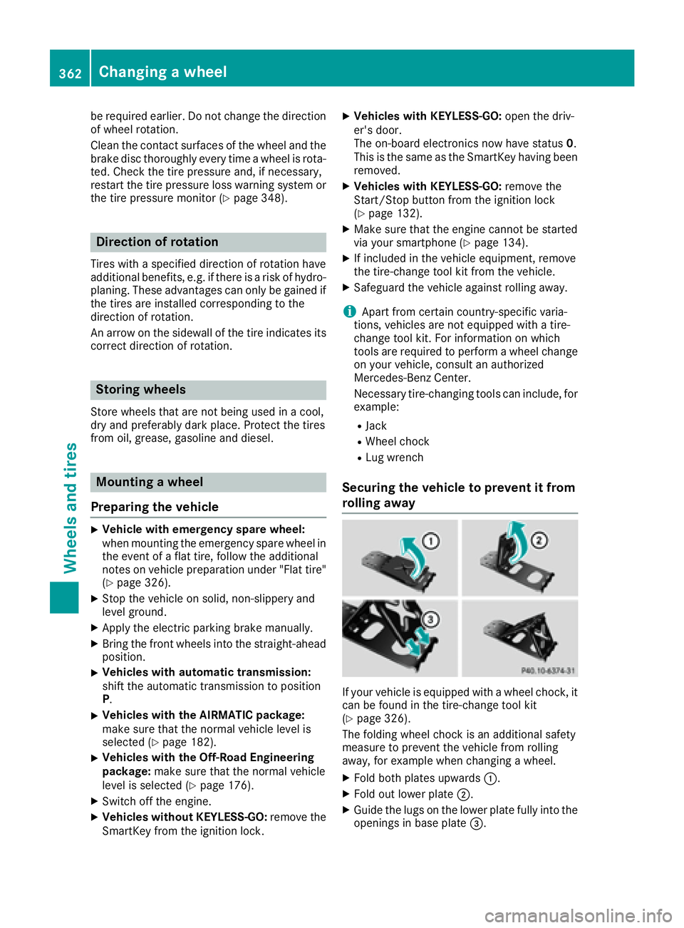
If your vehicle is equipped with a wheel chock, it
can be found in the tire-change tool kit
( Y
page 326).
The folding wheel chock is an additional safety
measure to prevent the vehicle from rolling
away, for example when changing a wheel. X
Fold both plates upwards C .X
Fold out lower plate D .X
Guide the lugs on the lower plate fully into the
openings in base plate
Page 365 of 390
X
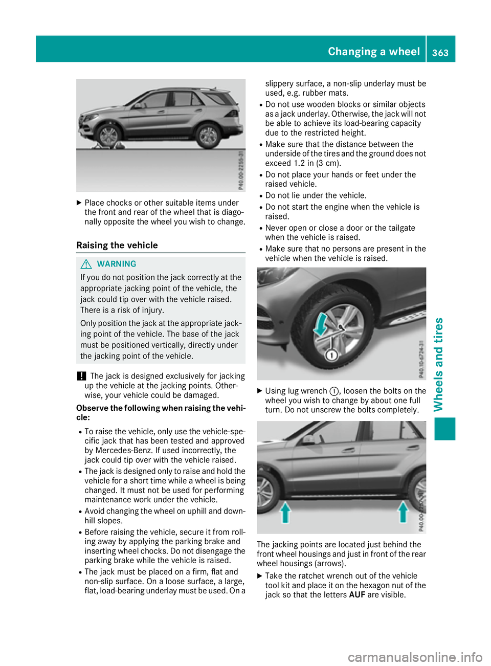
Place chocks or other suitable items under
the front and rear of the wheel that is diago-
nally opposite the wheel you wish to change.
Raising the vehicle
G WARNING
If you do not position the jack correctly at the
appropriate jacking point of the vehicle, the
jack could tip over with the vehicle raised.
There is a risk of injury.
Only position the jack at the appropriate jack-
ing point of the vehicle. The base of the jack
must be positioned vertically, directly under
the jacking point of the vehicle.
! The jack is designed exclusively for jacking
up the vehicle at the jacking points. Other-
wise, your vehicle could be damaged.
Observe the following when raising the vehi-
cle: R
To raise the vehicle, only use the vehicle-spe-
cific jack that has been tested and approved
by Mercedes-Benz. If used incorrectly, the
jack could tip over with the vehicle raised. R
The jack is designed only to raise and hold the
vehicle for a short time while a wheel is being
changed. It must not be used for performing
maintenance work under the vehicle. R
Avoid changing the wheel on uphill and down-
hill slopes. R
Before raising the vehicle, secure it from roll-
ing away by applying the parking brake and
inserting wheel chocks. Do not disengage the
parking brake while the vehicle is raised. R
The jack must be placed on a firm, flat and
non-slip surface. On a loose surface, a large,
flat, load-bearing underlay must be used. On a slippery surface, a non-slip underlay must be
used, e.g. rubber mats. R
Do not use wooden blocks or similar objects
as a jack underlay. Otherwise, the jack will not
be able to achieve its load-bearing capacity
due to the restricted height. R
Make sure that the distance between the
underside of the tires and the ground does not
exceed 1.2 in (3 cm). R
Do not place your hands or feet under the
raised vehicle. R
Do not lie under the vehicle. R
Do not start the engine when the vehicle is
raised. R
Never open or close a door or the tailgate
when the vehicle is raised. R
Make sure that no persons are present in the
vehicle when the vehicle is raised.
X
Using lug wrench C , loosen the bolts on the
wheel you wish to change by about one full
turn. Do not unscrew the bolts completely.
The jacking points are located just behind the
front wheel housings and just in front of the rear
wheel housings (arrows). X
Take the ratchet wrench out of the vehicle
tool kit and place it on the hexagon nut of the
jack so that the letters AUF are visible.Changing a wheel 363
Wheels and tires Z