tires MERCEDES-BENZ GLE 2019 Repair Manual
[x] Cancel search | Manufacturer: MERCEDES-BENZ, Model Year: 2019, Model line: GLE, Model: MERCEDES-BENZ GLE 2019Pages: 398, PDF Size: 12.25 MB
Page 379 of 398
R
only use a spare wheel or emergency spare
wheel of a different size briefly.
R do not switch ESP ®
off.
R have a spare wheel or emergency spare
wheel of a different size replaced at the
nearest qualified specialist workshop.
Observe that the wheel and tire dimensions
as well as the tire type must be correct.
! Mercedes-AMG vehicles with
"Minispare" emergency spare wheel: only
use the "Minispare" emergency spare wheel
on the rear axle. If you mount the
"Minispare" emergency spare wheel on the
front axle, this could result in damage to the
brake system.
If a tire on the front axle is defective, an intact
wheel from the rear axle must first be
replaced with the "Minispare" emergency
spare wheel. The damaged wheel on the front
axle can then be replaced by the undamaged wheel from the rear axle.
Make sure to note the placard on the
"Minispare" emergency spare wheel.
When using an emergency spare wheel or spare wheel of a different size, you must not exceed
the maximum speed of 50 mph (80 km/h).
You should regularly check the pressure of the
emergency spare wheel, particularly prior to
long trips, and correct the pressure as neces-
sary (Y page 354). The value on the wheel is
valid.
Snow chains must not be mounted on emer-
gency spare wheels. General notes
Information regarding permitted emergency
spare wheels can be found at an authorized
Mercedes-Benz Center.
Mounting the emergency spare wheel is descri- bed under "Mounting a wheel" (Y page 372).
An emergency spare wheel may also be moun-
ted against the direction of rotation. Observe
the time restriction on use as well as the speed
limitation specified on the emergency spare
wheel.
Replace the tires after six years at the latest,
regardless of wear. This also applies to the
emergency spare wheel. When you are driving with the collapsible spare
wheel mounted, the tire pressure loss warning
system or the tire pressure monitor cannot func-
tion reliably. Only restart the tire pressure loss
warning system or tire pressure monitor when
the defective wheel has been replaced with a
new wheel.
Vehicles with tire pressure monitor: after
mounting an emergency spare wheel, the sys-
tem may still display the tire pressure of the
removed wheel for a few minutes. The value dis- played for the mounted emergency spare wheelis not the same as the current tire pressure of
the emergency spare wheel. Removing/stowing the emergency
spare wheel
Vehicles with a "Minispare" emergency
spare wheel under the cargo compart-
ment floor Always observe the instructions and safety
notes in the "Mounting a wheel" section
(Y
page 372).
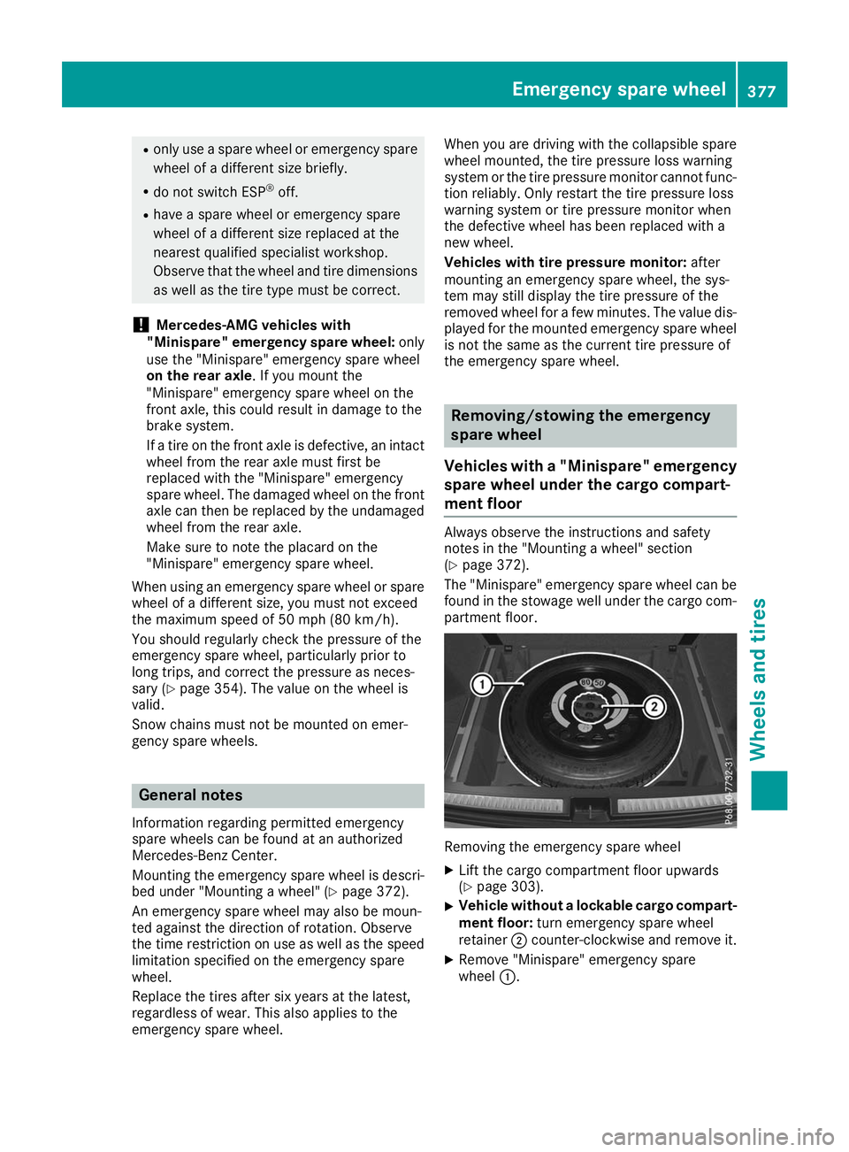
The "Minispare" emergency spare wheel can be found in the stowage well under the cargo com-
partment floor. Removing the emergency spare wheel
X Lift the cargo compartment floor upwards
(Y page 303).
X Vehicle without a lockable cargo compart-
ment floor: turn emergency spare wheel
retainer 0044counter-clockwise and remove it.
X Remove "Minispare" emergency spare
wheel 0043. Emergency spare wheel
377Wheels and tires Z
Page 380 of 398
X
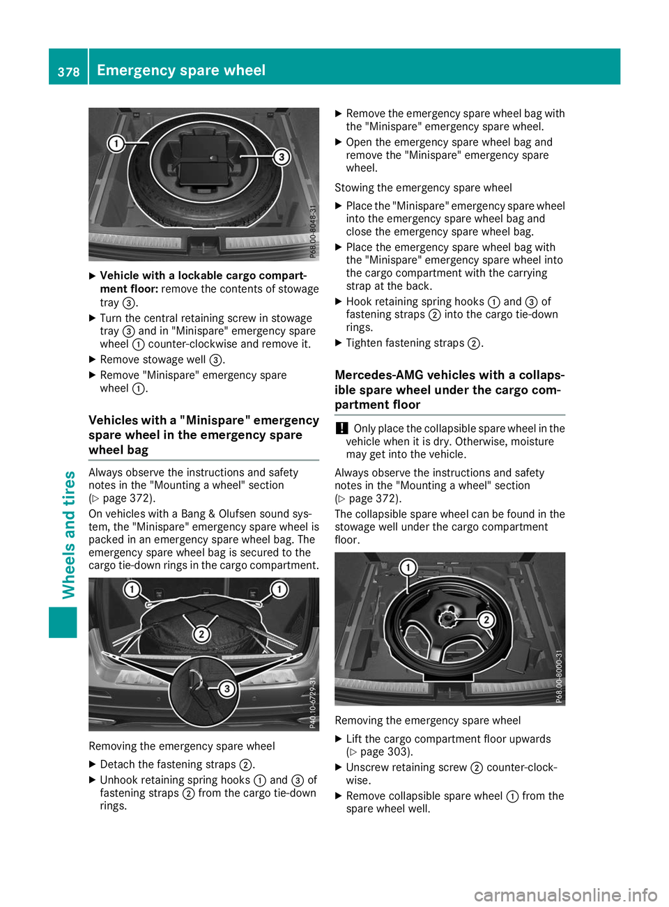
Vehicle with a lockable cargo compart-
ment floor:
remove the contents of stowage
tray 0087.
X Turn the central retaining screw in stowage
tray 0087and in "Minispare" emergency spare
wheel 0043counter-clockwise and remove it.
X Remove stowage well 0087.
X Remove "Minispare" emergency spare
wheel 0043.
Vehicles with a "Minispare" emergency
spare wheel in the emergency spare
wheel bag Always observe the instructions and safety
notes in the "Mounting a wheel" section
(Y page 372).
On vehicles with a Bang & Olufsen sound sys-
tem, the "Minispare" emergency spare wheel is
packed in an emergency spare wheel bag. The
emergency spare wheel bag is secured to the
cargo tie-down rings in the cargo compartment. Removing the emergency spare wheel
X Detach the fastening straps 0044.
X Unhook retaining spring hooks 0043and 0087of
fastening straps 0044from the cargo tie-down
rings. X
Remove the emergency spare wheel bag with
the "Minispare" emergency spare wheel.
X Open the emergency spare wheel bag and
remove the "Minispare" emergency spare
wheel.
Stowing the emergency spare wheel
X Place the "Minispare" emergency spare wheel
into the emergency spare wheel bag and
close the emergency spare wheel bag.
X Place the emergency spare wheel bag with
the "Minispare" emergency spare wheel into
the cargo compartment with the carrying
strap at the back.
X Hook retaining spring hooks 0043and 0087of
fastening straps 0044into the cargo tie-down
rings.
X Tighten fastening straps 0044.
Mercedes-AMG vehicles with a collaps-
ible spare wheel under the cargo com-
partment floor !
Only place the collapsible spare wheel in the
vehicle when it is dry. Otherwise, moisture
may get into the vehicle.
Always observe the instructions and safety
notes in the "Mounting a wheel" section
(Y page 372).
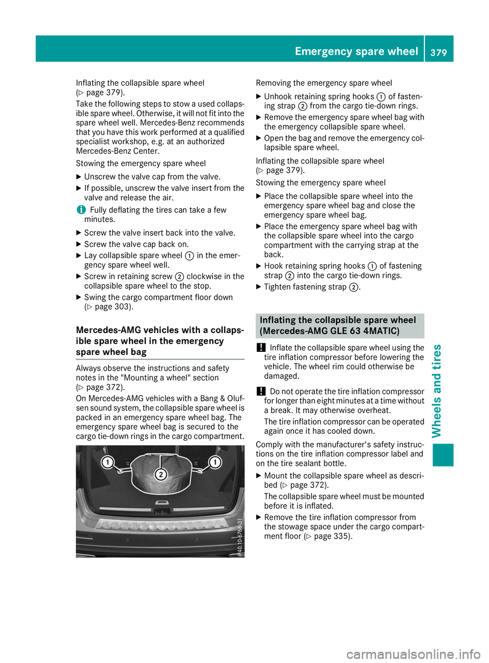
The collapsible spare wheel can be found in the stowage well under the cargo compartment
floor. Removing the emergency spare wheel
X Lift the cargo compartment floor upwards
(Y page 303).
X Unscrew retaining screw 0044counter-clock-
wise.
X Remove collapsible spare wheel 0043from the
spare wheel well. 378
Emergency spare wheelWheels and tires
Page 381 of 398
Inflating the collapsible spare wheel
(Y
page 379).
Take the following steps to stow a used collaps- ible spare wheel. Otherwise, it will not fit into the
spare wheel well. Mercedes-Benz recommends
that you have this work performed at a qualified
specialist workshop, e.g. at an authorized
Mercedes-Benz Center.
Stowing the emergency spare wheel
X Unscrew the valve cap from the valve.
X If possible, unscrew the valve insert from the
valve and release the air.
i Fully deflating the tires can take a few
minutes.
X Screw the valve insert back into the valve.
X Screw the valve cap back on.
X Lay collapsible spare wheel 0043in the emer-
gency spare wheel well.
X Screw in retaining screw 0044clockwise in the
collapsible spare wheel to the stop.
X Swing the cargo compartment floor down
(Y page 303).
Mercedes-AMG vehicles with a collaps-
ible spare wheel in the emergency
spare wheel bag Always observe the instructions and safety
notes in the "Mounting a wheel" section
(Y
page 372).
On Mercedes-AMG vehicles with a Bang & Oluf-
sen sound system, the collapsible spare wheel is
packed in an emergency spare wheel bag. The
emergency spare wheel bag is secured to the
cargo tie-down rings in the cargo compartment. Removing the emergency spare wheel
X Unhook retaining spring hooks 0043of fasten-
ing strap 0044from the cargo tie-down rings.
X Remove the emergency spare wheel bag with
the emergency collapsible spare wheel.
X Open the bag and remove the emergency col-
lapsible spare wheel.
Inflating the collapsible spare wheel
(Y page 379).
Stowing the emergency spare wheel
X Place the collapsible spare wheel into the
emergency spare wheel bag and close the
emergency spare wheel bag.
X Place the emergency spare wheel bag with
the collapsible spare wheel into the cargo
compartment with the carrying strap at the
back.
X Hook retaining spring hooks 0043of fastening
strap 0044into the cargo tie-down rings.
X Tighten fastening strap 0044. Inflating the collapsible spare wheel
(Mercedes-AMG GLE 63 4MATIC)
! Inflate the collapsible spare wheel using the
tire inflation compressor before lowering the
vehicle. The wheel rim could otherwise be
damaged.
! Do not operate the tire inflation compressor
for longer than eight minutes at a time without
a break. It may otherwise overheat.
The tire inflation compressor can be operated again once it has cooled down.
Comply with the manufacturer's safety instruc-
tions on the tire inflation compressor label and
on the tire sealant bottle.
X Mount the collapsible spare wheel as descri-
bed (Y page 372).
The collapsible spare wheel must be mounted before it is inflated.
X Remove the tire inflation compressor from
the stowage space under the cargo compart-
ment floor (Y page 335). Emergency spare wheel
379Wheels and tires Z
Page 382 of 398

X
Pull connector 0085and hose 0084out of the
housing.
X Remove the cap from the valve on the col-
lapsible spare wheel.
X Screw union nut 0044of hose 0084onto the valve.
X Make sure on/off switch 0083of the tire infla-
tion compressor is set to 0.
X Insert connector 0085into a socket in your vehi-
cle.
Cigarette lighter socket: (Y page 307)
12 V sockets: (Y page 308)
Observe the notes on the cigarette lighter
(Y page 307). Observe the notes on sockets
(Y page 308).
X Turn the SmartKey to position 0047in the igni-
tion lock (Y page 135).
X Press on and off switch 0083on the tire inflation
compressor to I.
The tire inflation compressor is switched on.
The tire is inflated. The tire pressure is shown on pressure gauge 0087.
X Inflate the tire to the specified tire pressure.
The specified tire pressure is printed on the
yellow label of the emergency spare wheel.
X When the specified tire pressure has been
reached, press on and off switch 0083on the
tire inflation compressor to 0.
The tire inflation compressor is switched off.
X Turn the SmartKey to position 0092in the igni-
tion lock.
X If the tire pressure is higher than the specified
pressure, press pressure release valve but-
ton 0043until the correct tire pressure has been
reached.
X Unscrew union nut 0044on hose 0084from the
valve.
X Screw the cap onto the valve of the collapsi-
ble spare wheel again. X
Stow connector 0085and hose 0084in the lower
section of the tire inflation compressor.
X Stow the tire inflation compressor in the vehi-
cle. 380
Emergency spare wheelWheels and tires
Page 392 of 398
R-134a refrigerant. Otherwise, the climate
control system may be damaged.
Service work, such as refilling with refrigerant or replacing component parts, may only be carried
out by a qualified specialist workshop. All appli- cable regulations, as well as SAE standard J639,
must be adhered to.
Always have work on the climate control system carried out at a qualified specialist workshop.
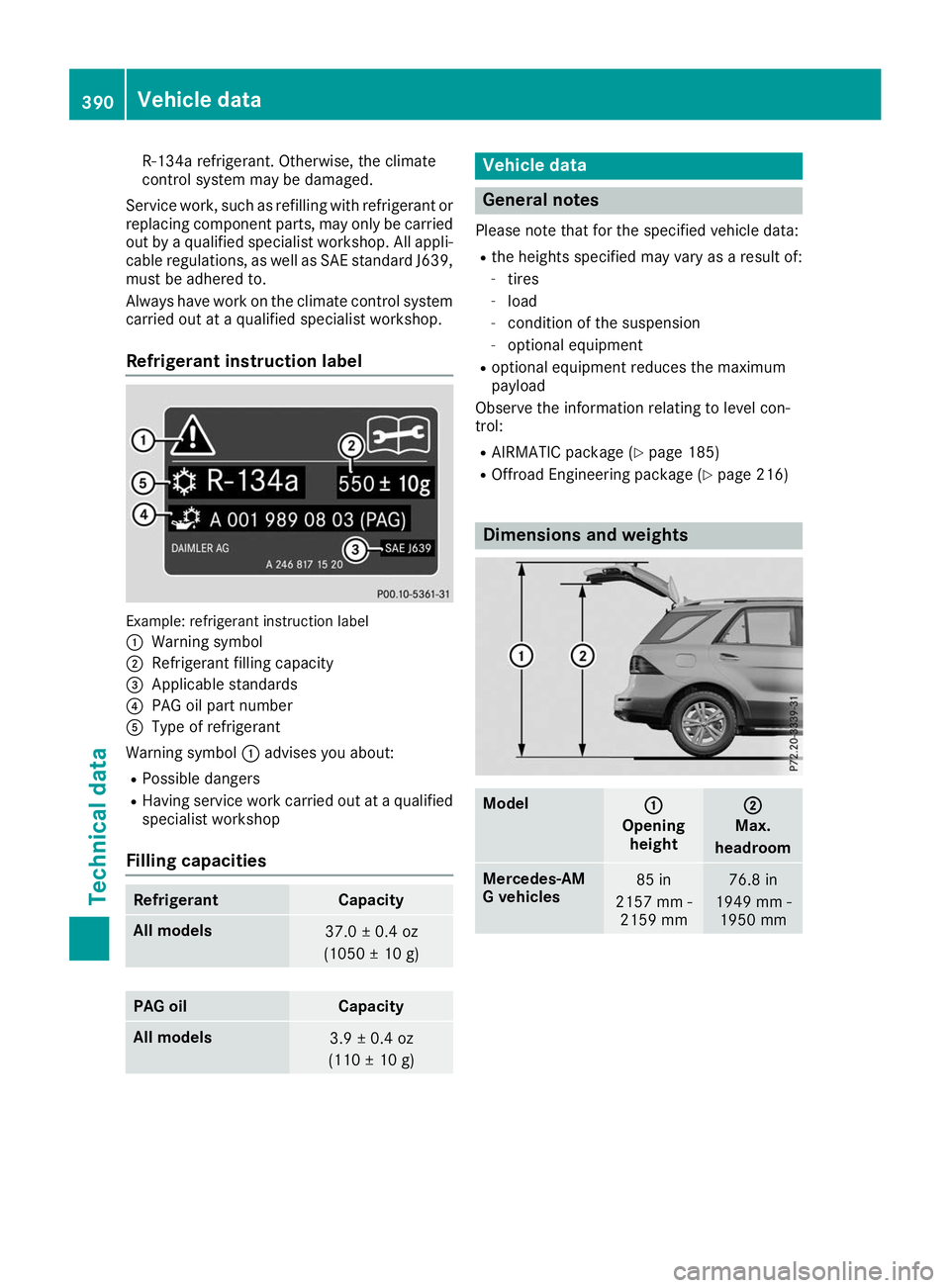
Refrigerant instruction label Example: refrigerant instruction label
0043 Warning symbol
0044 Refrigerant filling capacity
0087 Applicable standards
0085 PAG oil part number
0083 Type of refrigerant
Warning symbol 0043advises you about:
R Possible dangers
R Having service work carried out at a qualified
specialist workshop
Filling capacities Refrigerant Capacity
All models
37.0 ± 0.4 oz
(1050 ± 10 g) PAG oil Capacity
All models
3.9 ± 0.4 oz
(110 ± 10 g) Vehicle data
General notes
Please note that for the specified vehicle data: R the heights specified may vary as a result of:
- tires
- load
- condition of the suspension
- optional equipment
R optional equipment reduces the maximum
payload
Observe the information relating to level con-
trol:
R AIRMATIC package (Y page 185)
R Offroad Engineering package (Y page 216) Dimensions and weights
Model
0043 0043
Opening height 0044
0044
Max.
headroom Mercedes‑AM
G vehicles
85 in
2157 mm - 2159 mm 76.8 in
1949 mm - 1950 mm 390
Vehicle dataTechnical data