service indicator MERCEDES-BENZ GLE-Class 2016 C292 Owner's Manual
[x] Cancel search | Manufacturer: MERCEDES-BENZ, Model Year: 2016, Model line: GLE-Class, Model: MERCEDES-BENZ GLE-Class 2016 C292Pages: 382, PDF Size: 8.83 MB
Page 15 of 382
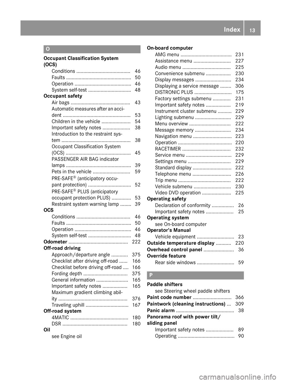
O
Occupant Classification System
(OCS)Conditions ....................................... 46
Faults ............................................... 50
Operation ......................................... 46
System self-test .............................. .48
Occupant safety
Air bags .......................................... .43
Automatic measures after an acci-
dent ................................................. 53
Children in the vehicle ..................... 54
Important safety notes .................... 38
Introduction to the restraint sys-
tem .................................................. 38
Occupant Classification System
(OCS) ............................................... 45
PASSENGER AIR BAG indicator
lamps ............................................... 39
Pets in the vehicle ........................... 59
PRE-SAFE
®(anticipatory occu-
pant protection) ............................... 52
PRE-SAFE
®PLUS (anticipatory
occupant protection PLUS) .............. 53
Restraint system warning lamp ........ 39
OCS
Conditions ....................................... 46
Faults ............................................... 50
Operation ......................................... 46
System self-test ............................... 48
Odometer ........................................... 222
Off-road driving
Approach/departure angle ............ 375
Checklist after driving off-road ...... 166
Checklist before driving off-road .... 166
Fording depth ................................ 375
General information ....................... 165
Important safety notes .................. 165
Maximum gradient climbing abil-
ity .................................................. 376
Traveling uphill ............................... 167
Off-road system
4MATIC .......................................... 180
DSR ............................................... 180
Oil
see Engine oil On-board computer
AMG menu ..................................... 231
Assistance menu ........................... 227
Audio menu ................................... 225
Convenience submenu .................. 230
Display messages .......................... 234
Displaying a service message ........ 306
DISTRONIC PLUS ........................... 175
Facto ry se
ttings submenu ............. 231
Important safety notes .................. 219
Instrument cluster submenu .......... 229
Lighting submenu .......................... 229
Menu overview .............................. 222
Message memory .......................... 234
Navigation menu ............................ 223
Operation ....................................... 220
RACETIMER ................................... 232
Service menu ................................. 229
Settings menu ............................... 229
Standard display ............................ 222
Telephone menu ............................ 226
Trip menu ...................................... 222
Vehicle submenu ........................... 230
Video DVD operation ..................... 225
Operating safety
Declaration of conformity ................ 26
Important safety notes .................... 25
Operating system
see On-board computer
Operator's Manual
Vehicle equipment ........................... 23
Outside temperature display ........... 220
Overhead control panel ...................... 36
Override feature
Rear side windows ........................... 59
P
Paddle shifterssee Steering wheel paddle shifters
Paint code number ............................ 366
Paintwork (cleaning instructions) ... 309
Panic alarm .......................................... 38
Panorama roof with power tilt/
sliding panel
Important safety notes .................... 89
Operating ......................................... 90
Index13
Page 73 of 382
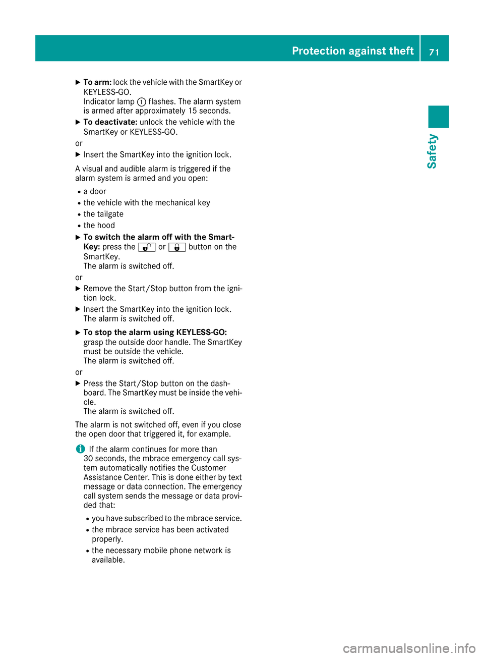
XTo arm:lock the vehicle with the SmartKey or
KEYLESS-GO.
Indicator lamp :flashes. The alarm system
is armed after approximately 15 seconds.
XTo deactivate: unlock the vehicle with the
SmartKey or KEYLESS-GO.
or
XInsert the SmartKey into the ignition lock.
A visual and audible alarm is triggered if the
alarm system is armed and you open:
Ra door
Rthe vehicle with the mechanical key
Rthe tailgate
Rthe hood
XTo switch the alarm off with the Smart-
Key: press the %or& button on the
SmartKey.
The alarm is switched off.
or
XRemove the Start/Stop button from the igni-
tion lock.
XInsert the SmartKey into the ignition lock.
The alarm is switched off.
XTo stop the alarm using KEYLESS-GO:
grasp the outside door handle. The SmartKey
must be outside the vehicle.
The alarm is switched off.
or
XPress the Start/Stop button on the dash-
board. The SmartKey must be inside the vehi- cle.
The alarm is switched off.
The alarm is not switched off, even if you close
the open door that triggered it, for example.
iIf the alarm continues for more than
30 seconds, the mbrace emergency call sys-
tem automatically notifies the Customer
Assistance Center. This is done either by text message or data connection. The emergency
call system sends the message or data pro vi-
d
ed that:
Ryou have subscribed to the mbrace service.
Rthe mbrace service has been activated
properly.
Rthe necessary mobile phone network is
available.
Protection against theft71
Safety
Z
Page 293 of 382

Problems with the 115 V power socket
ProblemPossible causes/consequences andMSolutions
The warning lamp on the
115 V power socket is
not lit.The on-board voltage is too low because the battery is too weak.
XStart the engine.
or
XCharge the battery (Ypage 322).
If the indicator lamp still does not light up:
XVisit a qualified specialist workshop.
The temperature of the DC/AC converter is temporarily too high.
XRemove the electronic device connector from the 115 V socket.
XLet the DC/AC converter cool down.
If the indicator lamp still does not light up after cooling down the
converter:
XVisit a qualified specialist workshop.
You have connected an electronic device that has a constant nominal
power of less than 150 watts, but has a very high switch-on current.
This device will not work. If you connect such a device, the 115 V
power socket will not supply it with power.
XConnect a suitable electronic device.
mbrace
General notes
The mbrace system is only available in the USA.
You must have a license agreement to activate
the mbrace service. Make sure that your system
is activated and operational. To log in, press the
ï MB Info call button. If any of the steps
mentioned are not carried out, the system may
not be activated.
If you have questions about the activation, con-
tact one of the following telephone hotlines:
Mercedes-Benz Customer Assistance Center at
1-800-FOR-MERCedes (1-800-367-6372) or
1-866-990-9007
Shortly after successfully registering with the
mbrace service, a user ID and password will be
sent to you by mail. You can use this password
to log onto the mbrace area under "Owners
Online" at http://www.mbusa.com. The system is available if:
Rit has been activated and is operational
Rthe corresponding mobile phone network is
available for transmitting data to the Cus-
tomer Center
Ra service subscription is available
Determining the location of the vehicle on a map
is only possible if:
RGPS reception is available.
Rthe vehicle position can be forwarded to the
Customer Assistance Center.
The mbrace system
To adjust the volume during a call, proceed as
follows:
XPress the WorX button on the multi-
function steering wheel.
or
XUse the volume control on the multimedia
system.
Features291
Stowage and features
Z
Page 294 of 382
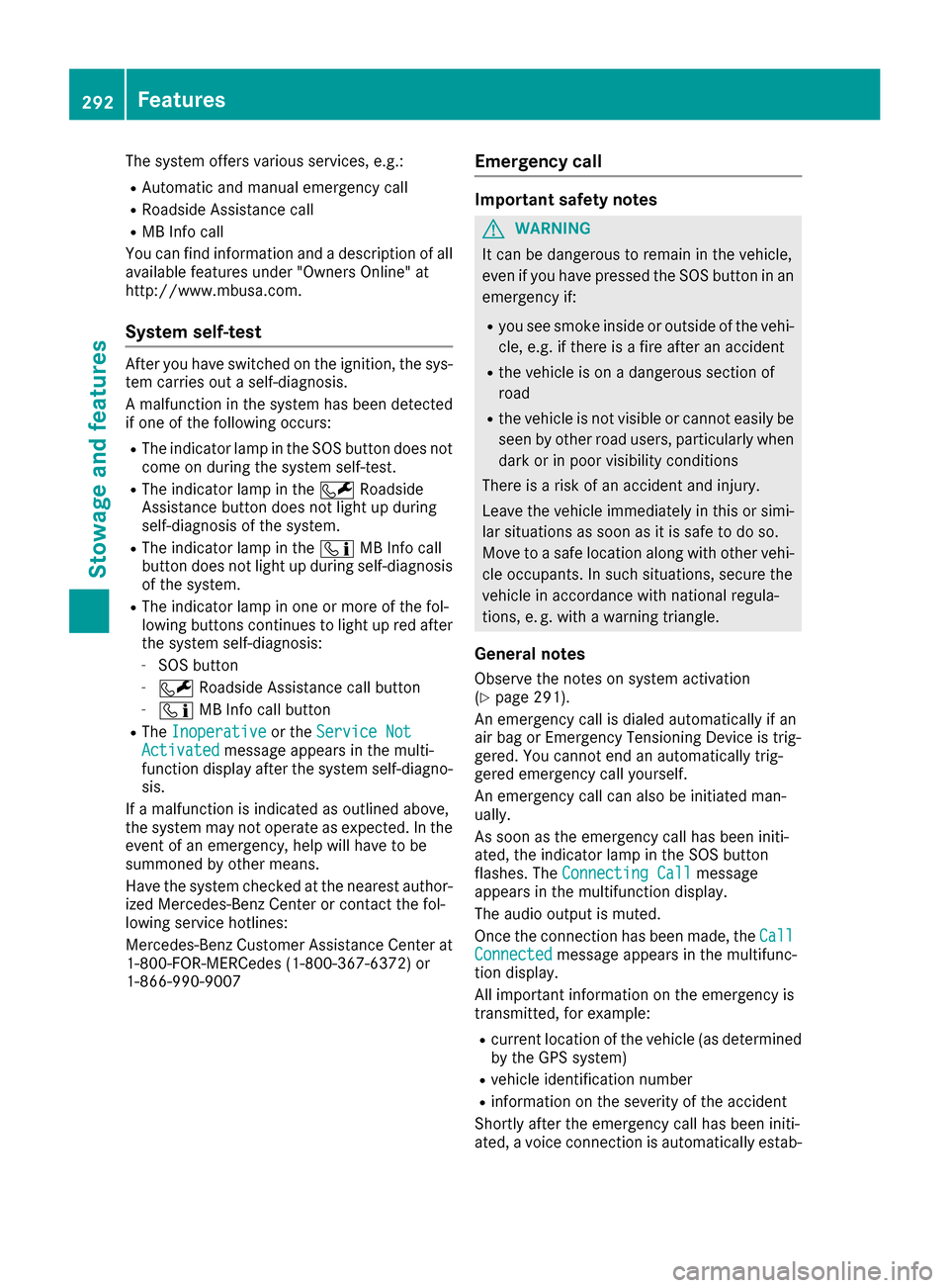
The system offers various services, e.g.:
RAutomatic and manual emergency call
RRoadside Assistance call
RMB Info call
You can find information and a description of all
available features under "Owners Online" at
http://www.mbusa.com.
System self-test
After you have switched on the ignition, the sys- tem carries out a self-diagnosis.
A malfunction in the system has been detected
if one of the following occurs:
RThe indicator lamp in the SOS button does not
come on during the system self-test.
RThe indicator lamp in the FRoadside
Assistance button does not light up during
self-diagnosis of the system.
RThe indicator lamp in the ïMB Info call
button does not light up during self-diagnosis
of the system.
RThe indicator lamp in one or more of the fol-
lowing buttons continues to light up red after
the system self-diagnosis:
-SOS button
-F Roadside Assistance call button
-ïMB Info call button
RTheInoperativeor the Service NotActivatedmessage appears in the multi-
function display after the system self-diagno-
sis.
If a malfunction is indicated as outlined above,
the system may not operate as expected. In the event of an emergency, help will have to be
summoned by other means.
Have the system checked at the nearest author-
ized Mercedes-Benz Center or contact the fol-
lowing service hotlines:
Mercedes-Benz Customer Assistance Center at 1-800-FOR-MERCedes (1-800-367-6372) or
1-866-990-9007
Emergency call
Important safety notes
GWARNING
It can be dangerous to remain in the vehicle,
even if you have pressed the SOS button in an emergency if:
Ryou see smoke inside or outside of the vehi-
cle, e.g. if there is a fire after an accident
Rthe vehicle is on a dangerous section of
road
Rthe vehicle is not visible or cannot easily beseen by other road users, particularly when
dark or in poor visibility conditions
There is a risk of an accident and injury.
Leave the vehicle immediately in this or simi-
lar situations as soon as it is safe to do so.
Move to a safe location along with other vehi-
cle occupants. In such situations, secure the
vehicle in accordance with national regula-
tions, e. g. with a warning triangle.
General notes
Observe the notes on system activation
(Ypage 291).
An emergency call is dialed automatically if an
air bag or Emergency Tensioning Device is trig-
gered. You cannot end an automatically trig-
gered emergency call yourself.
An emergency call can also be initiated man-
ually.
As soon as the emergency call has been initi-
ated, the indicator lamp in the SOS button
flashes. The Connecting Call
message
appears in the multifunction display.
The audio output is muted.
Once the connection has been made, the Call
Connectedmessage appears in the multifunc-
tion display.
All important information on the emergency is
transmitted, for example:
Rcurrent location of the vehicle (as determined by the GPS system)
Rvehicle identification number
Rinformation on the severity of the accident
Shortly after the emergency call has been initi-
ated, a voice connection is automatically estab-
292Features
Stowage and features
Page 295 of 382
lished between the Customer Assistance Center
and the vehicle occupants.
RIf the vehicle occupants respond, the
Mercedes-Benz Customer Assistance Center
attempts to get more information on the
emergency.
RIf there is no response from the vehicle occu-pants, an ambulance is immediately sent to
the vehicle.
If no voice connection can be established to the
Mercedes-Benz Customer Assistance Center,
the system has been unable to initiate an emer-
gency call.
This can occur, for example, if the relevant
mobile phone network is not available. The indi-
cator lamp in the SOS button flashes continu-
ously.
The Call Failed
message appears in the mul-
tifunction display and must be confirmed.
In this case, summon assistance by other
means.
Making an emergency call
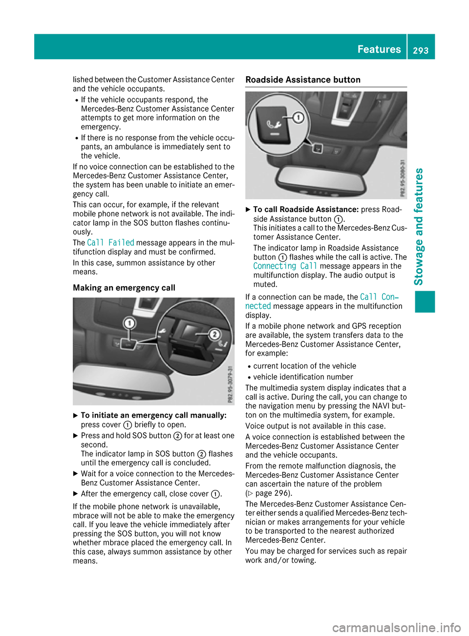
XTo initiate an emergency call manually:
press cover :briefly to open.
XPress and hold SOS button ;for at least one
second.
The indicator lamp in SOS button ;flashes
until the emergency call is concluded.
XWait for a voice connection to the Mercedes-
Benz Customer Assistance Center.
XAfter the emergency call, close cover :.
If the mobile phone network is unavailable,
mbrace will not be able to make the emergency
call. If you leave the vehicle immediately after
pressing the SOS button, you will not know
whether mbrace placed the emergency call. In
this case, always summon assistance by other
means.
Roadside Assistance button
XTo call Roadside Assistance: press Road-
side Assistance button :.
This initiates a call to the Mercedes-Benz Cus-
tomer Assistance Center.
The indicator lamp in Roadside Assistance
button :flashes while the call is active. The
Connecting Call
message appears in the
multifunction display. The audio output is
muted.
If a connection can be made, the Call Con‐
nectedmessage appears in the multifunction
display.
If a mobile phone network and GPS reception
are available, the system transfers data to the
Mercedes-Benz Customer Assistance Center,
for example:
Rcurrent location of the vehicle
Rvehicle identification number
The multimedia system display indicates that a
call is active. During the call, you can change to
the navigation menu by pressing the NAVI but-
ton on the multimedia system, for example.
Voice output is not available in this case.
A voice connection is established between the
Mercedes-Benz Customer Assistance Center
and the vehicle occupants.
From the remote malfunction diagnosis, the
Mercedes-Benz Customer Assistance Center
can ascertain the nature of the problem
(
Ypage 296).
The Mercedes-Benz Customer Assistance Cen-
ter either sends a qualified Mercedes-Benz tech-
nician or makes arrangements for your vehicle
to be transported to the nearest authorized
Mercedes-Benz Center.
You may be charged for services such as repair
work and/or towing.
Features293
Stowage and features
Z
Page 296 of 382
You can find more information in the separate
mbrace manual.
The system has not been able to initiate a Road-
side Assistance call, if:
Rthe indicator lamp for Roadside Assistance
call buttonFis flashing continuously.
Rno voice connection to the Mercedes-Benz
Customer Assistance Center was estab-
lished.
This can occur if the relevant mobile phone net-
work is not available, for example.
The Call Failed
message appears in the mul-
tifunction display.
XTo end a call: press the~button on the
multifunction steering wheel.
or
XPress the corresponding multimedia system
button for ending a phone call.
MB Info call button
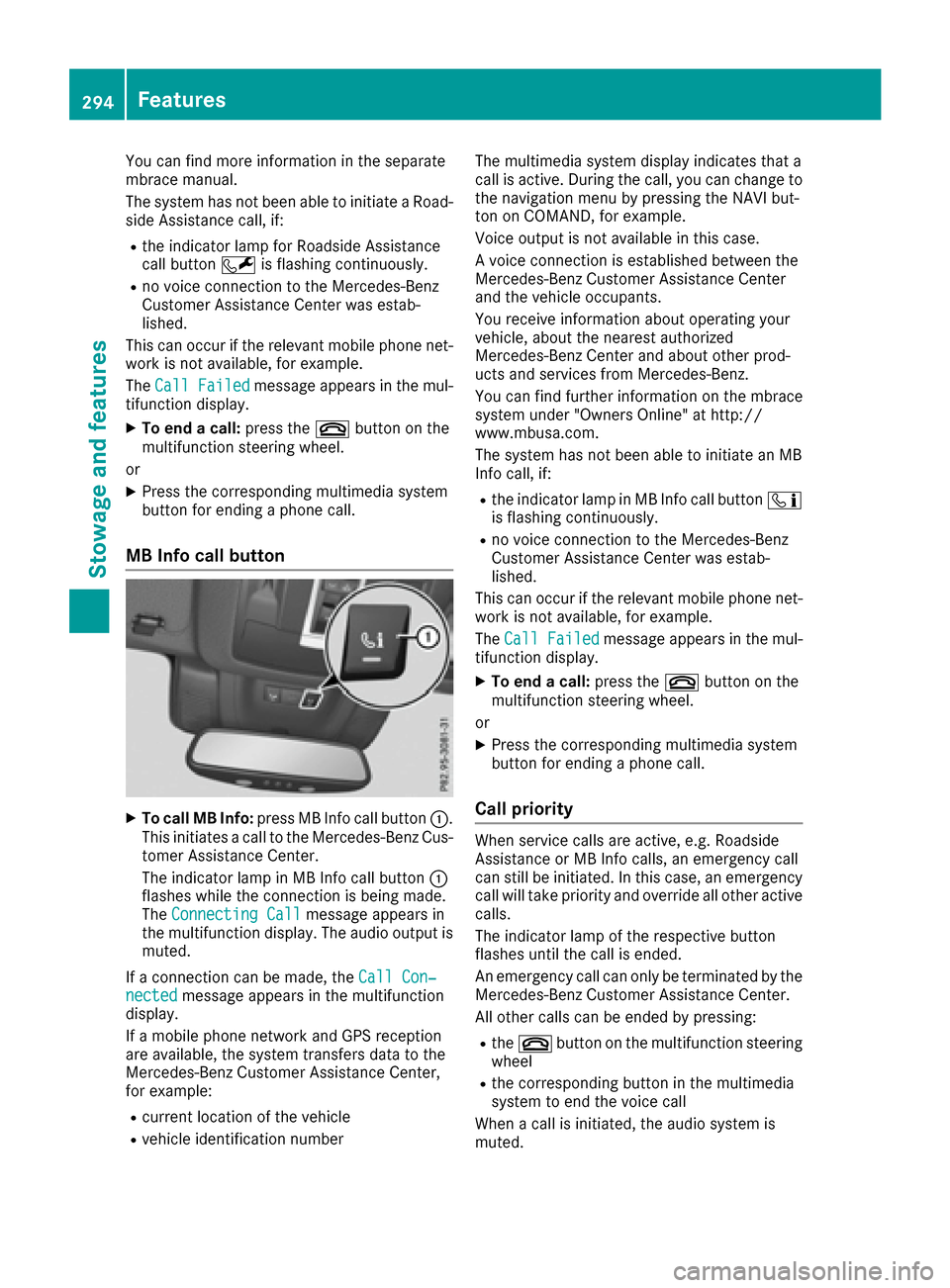
XTo call MB Info: press MB Info call button :.
This initiates a call to the Mercedes-Benz Cus-
tomer Assistance Center.
The indicator lamp in MB Info call button :
flashes while the connection is being made.
The Connecting Call
message appears in
the multifunction display. The audio output is
muted.
If a connection can be made, the Call Con‐
nectedmessage appears in the multifunction
display.
If a mobile phone network and GPS reception
are available, the system transfers data to the
Mercedes-Benz Customer Assistance Center,
for example:
Rcurrent location of the vehicle
Rvehicle identification number The multimedia system display indicates that a
call is active. During the call, you can change to
the navigation menu by pressing the NAVI but-
ton on COMAND, for example.
Voice output is not available in this case.
A voice connection is established between the
Mercedes-Benz Customer Assistance Center
and the vehicle occupants.
You receive information about operating your
vehicle, about the nearest authorized
Mercedes-Benz Center and about other prod-
ucts and services from Mercedes-Benz.
You can find further information on the mbrace
system under "Owners Online" at http://
www.mbusa.com.
The system has not been able to initiate an MB
Info call, if:
Rthe indicator lamp in MB Info call button
ï
is flashing continuously.
Rno voice connection to the Mercedes-Benz
Customer Assistance Center was estab-
lished.
This can occur if the relevant mobile phone net-
work is not available, for example.
The Call Failed
message appears in the mul-
tifunction display.
XTo end a call: press the~button on the
multifunction steering wheel.
or
XPress the corresponding multimedia system
button for ending a phone call.
Call priority
When service calls are active, e.g. Roadside
Assistance or MB Info calls, an emergency call
can still be initiated. In this case, an emergency
call will take priority and override all other active
calls.
The indicator lamp of the respective button
flashes until the call is ended.
An emergency call can only be terminated by the
Mercedes-Benz Customer Assistance Center.
All other calls can be ended by pressing:
Rthe ~ button on the multifunction steering
wheel
Rthe corresponding button in the multimedia
system to end the voice call
When a call is initiated, the audio system is
muted.
294Features
Stowage and features
Page 324 of 382
The vehicle will then use very little energy, thus
conserving battery power.
If the power supply has been interrupted, e.g. ifyou reconnect the battery, you will have to:
Rset the clock. Information on setting the clock
can be found in the Digital Operator's Manual.
On vehicles with a multimedia system and
navigation system, the clock is set automati-
cally.
Rreset the function for folding the exterior mir-
rors in/out automatically, by folding the mir-
rors out once (
Ypage 105).
Charging the 12 V battery
GWARNING
During charging and jump-starting, explosive
gases can escape from the battery. There is a risk of an explosion.
Particularly avoid fire, open flames, creating
sparks and smoking. Ensure there is sufficient
ventilation while charging and jump-starting.
Do not lean over a battery.
GWARNING
Battery acid is caustic. There is a risk of injury.
Avoid contact with skin, eyes or clothing. Do
not inhale any battery gases. Do not lean over
the battery. Keep children away from batter-
ies. Wash away battery acid immediately with
plenty of clean water and seek medical atten-
tion.
GWARNING
A discharged battery can freeze at tempera-
tures below freezing point. When jump-start-
ing the vehicle or charging the battery, gases can escape from the battery. There is a risk of
an explosion.
Allow the frozen battery to thaw out before
charging it or jump-starting.
!Only use battery chargers with a maximum
charging voltage of 14.8 V.
!Only charge the battery using the jump-
starting connection point. The jump-starting connection point is in the
engine compartment (
Ypage 323).
XOpen the hood.
XConnect the battery charger to the positive
terminal and ground point in the same order
as when connecting the donor battery in the
jump-starting procedure (
Ypage 323).
Keep away from fire and open flames. Do not
lean over a battery. Never charge the battery if it
is still installed in the vehicle, unless you use a
battery charger which has been tested and
approved by Mercedes-Benz. A battery charger
unit specially adapted for Mercedes-Benz vehi-
cles and tested and approved by Mercedes-
Benz is available as an accessory. It permits the
charging of the battery in its installed position.
Contact an authorized Mercedes-Benz Center
for further information and availability. Read the
battery charger's operating instructions before
charging the battery.
If, at low temperatures, the indicator lamps/
warning lamps in the instrument cluster do not
light up, it is highly likely that the discharged
battery has frozen. In this case you may neither
jump-start the vehicle nor charge the battery.
The service life of a thawed-out battery may be
shorter. The starting characteristics can be
impaired, particularly at low temperatures. Have
the thawed-out battery checked at a qualified
specialist workshop.
322Battery (vehicle)
Breakdown assitance
Page 325 of 382
Jump-starting
For the jump-starting procedure, use only the jump-starting connection point in the engine com-
partment, consisting of a positive terminal and a ground point.
GWARNING
Battery acid is caustic. There is a risk of injury.
Avoid contact with skin, eyes or clothing. Do not inhale any battery gases. Do not lean over the
battery. Keep children away from batteries. Wash away battery acid immediately with plenty of
clean water and seek medical attention.
GWARNING
During charging and jump-starting, explosive gases can escape from the battery. There is a risk of an explosion.
Particularly avoid fire, open flames, creating sparks and smoking. Ensure there is sufficient ven-
tilation while charging and jump-starting. Do not lean over a battery.
GWARNING
During the charging process, a battery produces hydrogen gas. If a short circuit occurs or sparks
are created, the hydrogen gas can ignite. There is a risk of an explosion.
RMake sure that the positive terminal of a connected battery does not come into contact with
vehicle parts.
RNever place metal objects or tools on a battery.
RIt is important that you observe the described order of the battery terminals when connecting
and disconnecting a battery.
RWhen jump-starting, make sure that the battery poles with identical polarity are connected.
RIt is particularly important to observe the described order when connecting and disconnecting
the jumper cables.
RNever connect or disconnect the battery terminals while the engine is running.
GWARNING
A discharged battery can freeze at temperatures below freezing point. When jump-starting the
vehicle or charging the battery, gases can escape from the battery. There is a risk of an explosion. Allow the frozen battery to thaw out before charging it or jump-starting.
!Vehicles with a gasoline engine: avoid repeated and lengthy starting attempts. Otherwise, the
catalytic converter could be damaged by non-combusted fuel.
If the indicator/warning lamps do not light up at low temperatures, it is very likely that the dis-
charged battery has frozen. In this case you may neither jump-start the vehicle nor charge the
battery. The service life of a thawed-out battery may be shorter. The starting characteristics can be
impaired, particularly at low temperatures. Have the thawed-out battery checked at a qualified
specialist workshop.
Jump-starting323
Breakdown assitance
Z
Page 333 of 382
Regular checking of wheels and tires
GWARNING
Damaged tires can cause tire inflation pres-
sure loss. As a result, you could lose control of
your vehicle. There is a risk of accident.
Check the tires regularly for signs of damage
and replace any damaged tires immediately.
Check wheels and tires for damage at least once
a month. Check wheels and tires after driving
off-road or on rough roads. Damaged wheels
can cause a loss of tire pressure. Pay particular
attention to damage such as:
Rcuts in the tires
Rpunctures
Rtears in the tires
Rbulges on tires
Rdeformation or severe corrosion on wheels
Regularly check the tire tread depth and the
condition of the tread across the whole width of
the tire (
Ypage 331). If necessary, turn the
front wheels to full lock in order to inspect the
inner side of the tire surface.
All wheels must have a valve cap to protect the
valve against dirt and moisture. Do not mount
anything onto the valve other than the standard
valve cap or other valve caps approved by
Mercedes-Benz for your vehicle. Do not use any
other valve caps or systems, e.g. tire pressure
monitoring systems.
Regularly check the pressure of all the tires par-
ticularly prior to long trips. Adjust the tire pres-
sure as necessary (
Ypage 333).
Observe the notes on the emerge ncy sp
are
wheel (Ypage 360).
The service life of tires depends, among other
things, on the following factors:
Rdriving style
Rtire pressure
Rdistance covered
Notes on tire tread
GWARNING
Insufficient tire tread will reduce tire traction.
The tire is no longer able to dissipate water.
This means that on wet road surfaces, the risk
of hydroplaning increases, in particular where speed is not adapted to suit the driving con-
ditions. There is a risk of accident.
If the tire pressure is too high or too low, tires
may exhibit different levels of wear at differ-
ent locations on the tire tread. Thus, you
should regularly check the tread depth and
the condition of the tread across the entire
width of all tires.
Minimum tire tread depth for:
RSummer tires: âin (3 mm)
RM+S tires: ãin (4 mm)
For safety reasons, replace the tires before
the legally prescribed limit for the minimum
tire tread depth is reached.
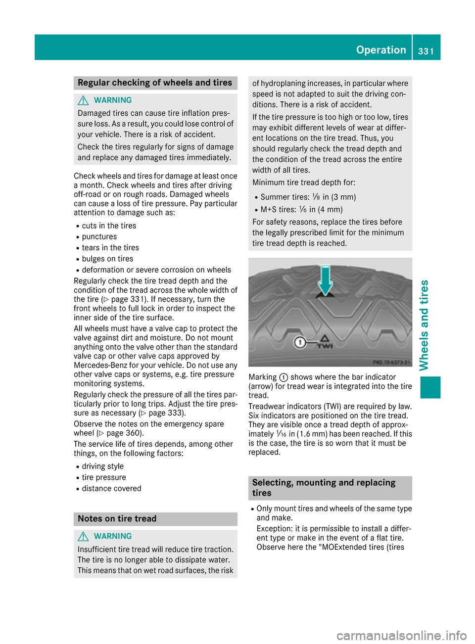
Marking :shows where the bar indicator
(arrow) for tread wear is integrated into the tire
tread.
Treadwear indicators (TWI) are required by law. Six indicators are positioned on the tire tread.
They are visible once a tread depth of approx-
imately áin (1.6 mm) has been reached. If this
is the case, the tire is so worn that it must be
replaced.
Selecting, mounting and replacing
tires
ROnly mount tires and wheels of the same type
and make.
Exception: it is permissible to install a differ-
ent type or make in the event of a flat tire.
Observe here the "MOExtended tires (tires
Operation331
Wheels and tires
Z
Page 338 of 382
Underinflated tires may:
Roverheat, leading to tire defects
Radversely affect handling
Rwear excessively and/or unevenly
Rhave an adverse effect on fuel consumption
Overinflated tires
GWARNING
Tires with excessively high pressure can burst
because they are damaged more easily by
road debris, potholes etc. In addition, they
also suffer from irregular wear, which can
severely impair the braking properties and the driving characteristics. There is a risk of an
accident.
Avoid tire pressures that are too high in all the
tires, including the spare wheel.
Overinflated tires may:
Rincrease the braking distance
Radversely affect handling
Rwear excessively and/or unevenly
Rhave an adverse effect on ride comfort
Rbe more susceptible to damage
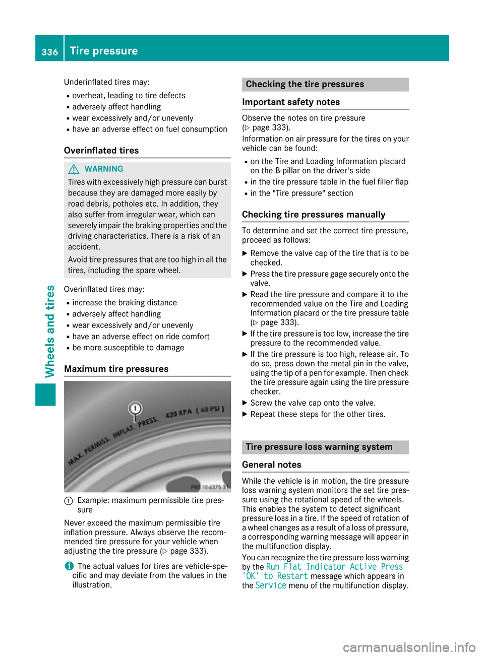
Maximum tire pressures
:Example: maximum permissible tire pres-
sure
Never exceed the maximum permissible tire
inflation pressure. Always observe the recom-
mended tire pressure for your vehicle when
adjusting the tire pressure (
Ypage 333).
iThe actual values for tires are vehicle-spe-
cific and may deviate from the values in the
illustration.
Checking the tire pressures
Important safety notes
Observe the notes on tire pressure
(Ypage 333).
Information on air pressure for the tires on your
vehicle can be found:
Ron the Tire and Loading Information placard
on the B-pillar on the driver's side
Rin the tire pressure table in the fuel filler flap
Rin the "Tire pressure" section
Checking tire pressures manually
To determine and set the correct tire pressure,
proceed as follows:
XRemove the valve cap of the tire that is to be
checked.
XPress the tire pressure gage securely onto the
valve.
XRead the tire pressure and compare it to the
recommended value on the Tire and Loading
Information placard or the tire pressure table (
Ypage 333).
XIf the tire pressure is too low, increase the tire
pressure to the recommended value.
XIf the tire pressure is too high, release air. To
do so, press down the metal pin in the valve,
using the tip of a pen for example. Then check
the tire pressure again using the tire pressure
checker.
XScrew the valve cap onto the valve.
XRepeat these steps for the other tires.
Tire pressure loss warning system
General notes
While the vehicle is in motion, the tire pressure
loss warning system monitors the set tire pres-
sure using the rotational speed of the wheels.
This enables the system to detect significant
pressure loss in a tire. If the speed of rotation of
a wheel changes as a result of a loss of pressure,
a corresponding warning message will appear in
the multifunction display.
You can recognize the tire pressure loss warning
by the Run Flat Indicator Active Press
'OK' to Restartmessage which appears in
the Servicemenu of the multifunction display.
336Tire pressure
Wheels and tires