height MERCEDES-BENZ GLE-CLASS SUV 2016 User Guide
[x] Cancel search | Manufacturer: MERCEDES-BENZ, Model Year: 2016, Model line: GLE-CLASS SUV, Model: MERCEDES-BENZ GLE-CLASS SUV 2016Pages: 450, PDF Size: 10.52 MB
Page 209 of 450
Selecting Sport Plus tuning (Mercedes-
AMG vehicles)
The very firm setting of the suspension setting in
theSport Plus drive program ensures the best
possible contact with the road. Select this drive
program when employing a sporty driving style, e.g. on winding country roads or primarily when
driving on race circuits.
DSR is not available in the Sport Plusdrive pro-
gram. For further information on DSR, see
(
Ypage 236).
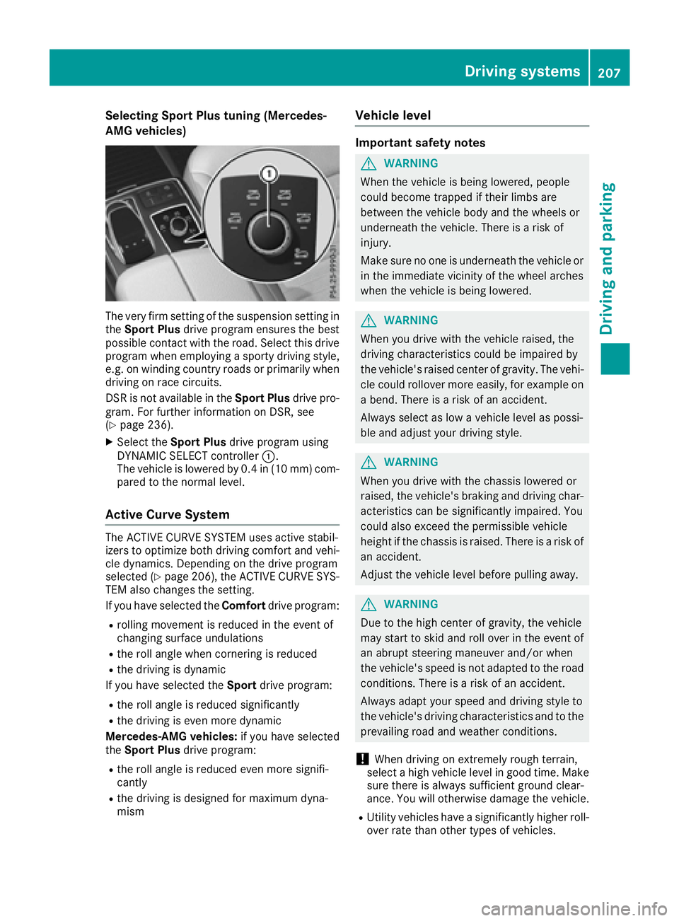
XSelect the Sport Plus drive program using
DYNAMIC SELECT controller :.
The vehicle is lowered by 0.4 in (10 mm) com-
pared to the normal level.
Active Curve System
The ACTIVE CURVE SYSTEM uses active stabil-
izers to optimize both driving comfort and vehi-
cle dynamics. Depending on the drive program
selected (
Ypage 206), the ACTIVE CURVE SYS-
TEM also changes the setting.
If you have selected the Comfortdrive program:
Rrolling movement is reduced in the event of
changing surface undulations
Rthe roll angle when cornering is reduced
Rthe driving is dynamic
If you have selected the Sportdrive program:
Rthe roll angle is reduced significantly
Rthe driving is even more dynamic
Mercedes-AMG vehicles: if you have selected
the Sport Plus drive program:
Rthe roll angle is reduced even more signifi-
cantly
Rthe driving is designed for maximum dyna-
mism
Vehicle level
Important safety notes
GWARNING
When the vehicle is being lowered, people
could become trapped if their limbs are
between the vehicle body and the wheels or
underneath the vehicle. There is a risk of
injury.
Make sure no one is underneath the vehicle or
in the immediate vicinity of the wheel arches
when the vehicle is being lowered.
GWARNING
When you drive with the vehicle raised, the
driving characteristics could be impaired by
the vehicle's raised center of gravity. The vehi-
cle could rollover more easily, for example on
a bend. There is a risk of an accident.
Always select as low a vehicle level as possi-
ble and adjust your driving style.
GWARNING
When you drive with the chassis lowered or
raised, the vehicle's braking and driving char-
acteristics can be significantly impaired. You
could also exceed the permissible vehicle
height if the chassis is raised. There is a risk of an accident.
Adjust the vehicle level before pulling away.
GWARNING
Due to the high center of gravity, the vehicle
may start to skid and roll over in the event of
an abrupt steering maneuver and/or when
the vehicle's speed is not adapted to the road
conditions. There is a risk of an accident.
Always adapt your speed and driving style to
the vehicle's driving characteristics and to the
prevailing road and weather conditions.
!When driving on extremely rough terrain,
select a high vehicle level in good time. Make
sure there is always sufficient ground clear-
ance. You will otherwise damage the vehicle.
RUtility vehicles have a significantly higher roll- over rate than other types of vehicles.
Driving systems207
Driving and parking
Z
Page 211 of 450
Setting the normal vehicle level
!Make sure that there is enough ground
clearance when the vehicle is being lowered.
It could otherwise hit the ground, damaging
the underbody.
XStart the engine.
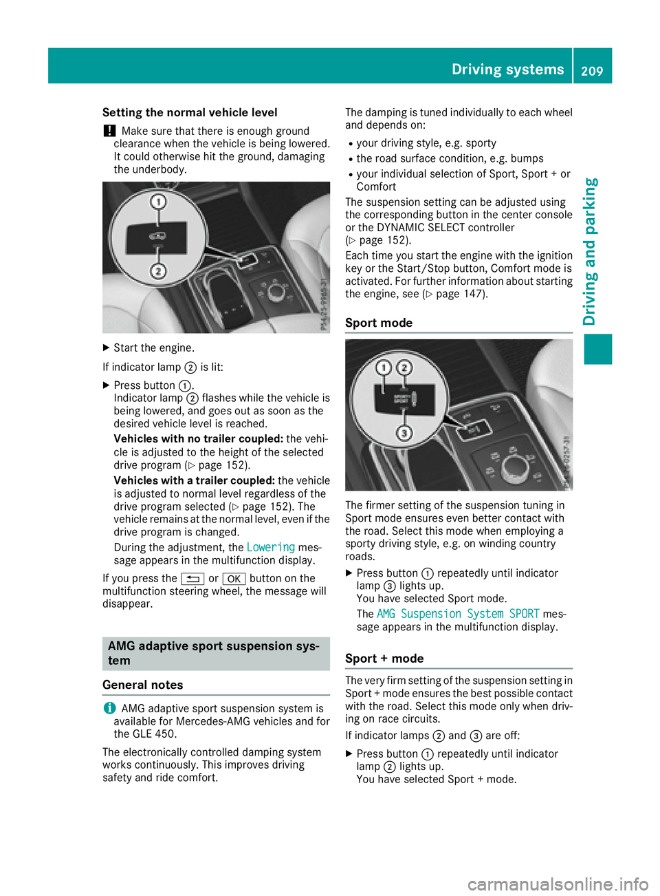
If indicator lamp ;is lit:
XPress button :.
Indicator lamp ;flashes while the vehicle is
being lowered, and goes out as soon as the
desired vehicle level is reached.
Vehicles with no trailer coupled: the vehi-
cle is adjusted to the height of the selected
drive program (
Ypage 152).
Vehicles with a trailer coupled: the vehicle
is adjusted to normal level regardless of the
drive program selected (
Ypage 152). The
vehicle remains at the normal level, even if the
drive program is changed.
During the adjustment, the Lowering
mes-
sage appears in the multifunction display.
If you press the %ora button on the
multifunction steering wheel, the message will
disappear.
AMG adaptive sport suspension sys-
tem
General notes
iAMG adaptive sport suspension system is
available for Mercedes-AMG vehicles and for
the GLE 450.
The electronically controlled damping system
works continuously. This improves driving
safety and ride comfort. The damping is tuned individually to each wheel
and depends on:
Ryour driving style, e.g. sporty
Rthe road surface condition, e.g. bumps
Ryour individual selection of Sport, Sport + or
Comfort
The suspension setting can be adjusted using
the corresponding button in the center console
or the DYNAMIC SELECT controller
(
Ypage 152).
Each time you start the engine with the ignition
key or the Start/Stop button, Comfort mode is
activated. For further information about starting
the engine, see (
Ypage 147).
Sport mode
The firmer setting of the suspension tuning in
Sport mode ensures even better contact with
the road. Select this mode when employing a
sporty driving style, e.g. on winding country
roads.
XPress button :repeatedly until indicator
lamp =lights up.
You have selected Sport mode.
The AMG Suspension System SPORT
mes-
sage appears in the multifunction display.
Sport + mode
The very firm setting of the suspension setting in
Sport + mode ensures the best possible contact
with the road. Select this mode only when driv-
ing on race circuits.
If indicator lamps ;and =are off:
XPress button :repeatedly until indicator
lamp ;lights up.
You have selected Sport + mode.
Driving systems209
Driving and parking
Z
Page 216 of 450
RSnowfall or heavy rain may lead to a parking
space being measured inaccurately.
RPay attention to the PARKTRONIC
(Ypage 211) warning messages during the
parking procedure.
RAt any time, you can intervene in the steering procedure to correct it. Active Parking Assist
will then be canceled.
RWhen transporting a load which protrudes
from your vehicle, you should not use Active
Parking Assist.
RNever use Active Parking Assist when snow
chains are installed.
RMake sure that the tire pressures are always
correct. This has a direct influence on the
parking characteristics of the vehicle.
Use Active Parking Assist for parking spaces:
Rparallel or at right angles to the direction of
travel
Rthat are on straight roads, not bends
Rthat are on the same level as the road, e.g. not
on the pavement
Detecting parking spaces
Objects located above the height range of Active Parking Assist will not be detected when the
parking space is measured. These are not taken
into account when the parking procedure is cal-
culated, e.g. overhanging loads, tail sections or
loading ramps of goods vehicles.
GWARNING
If there are objects above the detection range:
RActive Park Assist may steer too early
Rthe vehicle may not stop in front of these
objects
You may cause a collision as a result. There is
a risk of an accident.
If objects are located above the detection
range, stop and deactivate Active Parking
Assist.
For further information on the detection range
(
Ypage 210). Active Parking Assist does not assist you park-
ing in spaces at right angles to the direction of
travel if:
Rtwo parking spaces are located directly next
to one another
Rthe parking space is directly next to a low
obstacle such as a low curb
Ryou park forwards
Active Parking Assist does not assist you park-
ing in spaces that are parallel or at right angles
to the direction of travel if:
Rthe parking space is on a curb
Rthe system reads the parking space as being
blocked, for example by foliage or grass pav-
ing blocks
Rthe area is too small for the vehicle to maneu-
ver into
Rthe parking space is bordered by an obstacle,
e.g. a tree, a post or a trailer
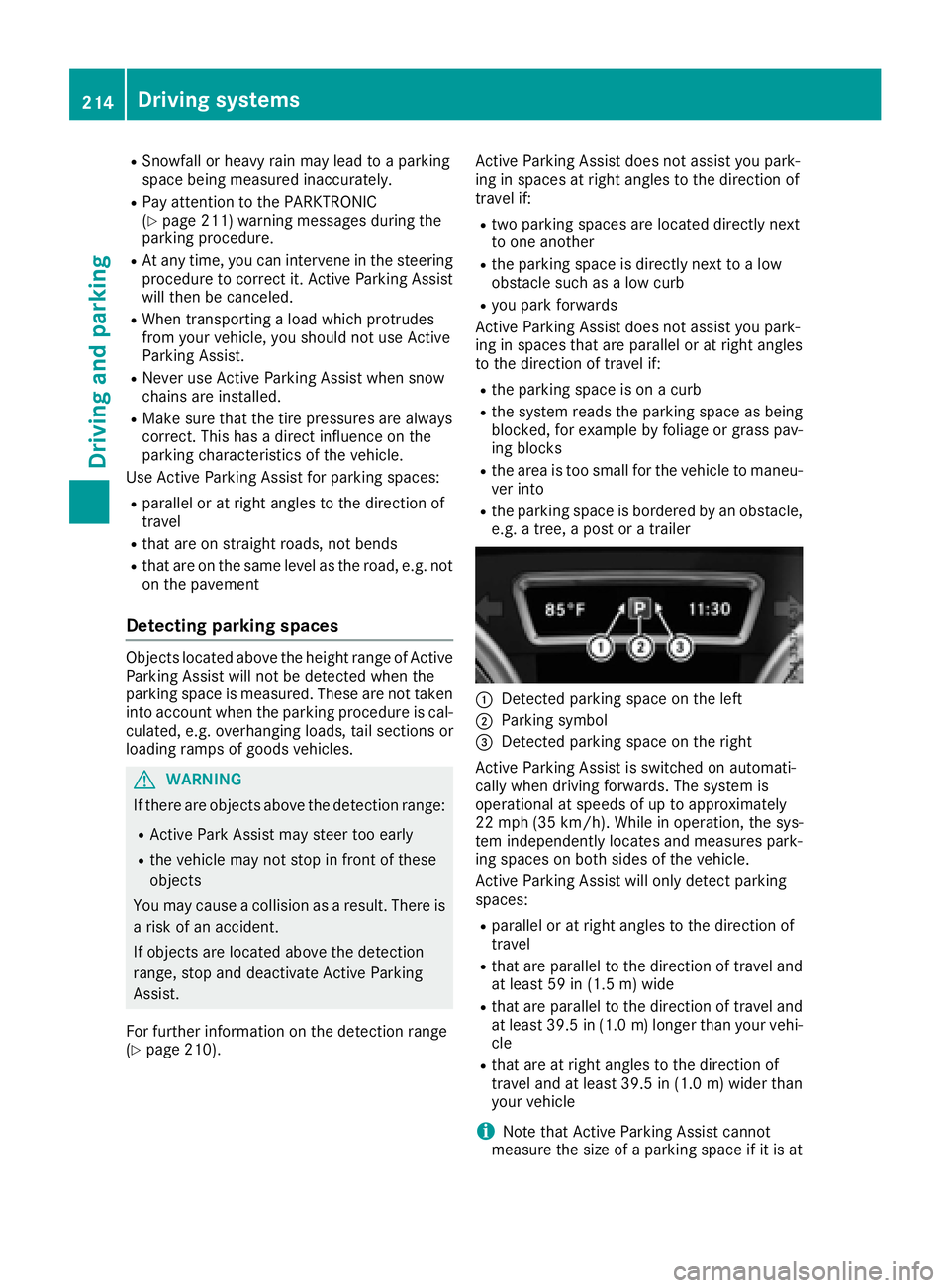
:Detected parking space on the left
;Parking symbol
=Detected parking space on the right
Active Parking Assist is switched on automati-
cally when driving forwards. The system is
operational at speeds of up to approximately
22 mph (35 km/h). While in operation, the sys-
tem independently locates and measures park-
ing spaces on both sides of the vehicle.
Active Parking Assist will only detect parking
spaces:
Rparallel or at right angles to the direction of
travel
Rthat are parallel to the direction of travel and
at least 59 in (1.5 m) wide
Rthat are parallel to the direction of travel and
at least 39.5 in (1.0 m)longer than your vehi-
cle
Rthat are at right angles to the direction of
travel and at least 39.5 in (1.0 m) wider than
your vehicle
iNote that Active Parking Assist cannot
measure the size of a parking space if it is at
214Driving systems
Driving and parking
Page 219 of 450
Canceling Active Parking Assist
XStop the movement of the multifunction
steering wheel or steer yourself.
Active Parking Assist will be canceled at once.
ThePark Assist Canceled
message
appears in the multifunction display.
or
XPress the PARKTRONIC button (Ypage 212).
PARKTRONIC is switched off and Active Park-
ing Assist is immediately canceled. The Park
Assist Canceledmessage appears in the
multifunction display.
Active Parking Assist is canceled automatically
if:
Rthe electric parking brake is engaged
Rtransmission position Pis selected
Rparking using Active Parking Assist is no lon-
ger possible
Ryou are driving faster than 6 mph (10 km/h)
Ra wheel spins, ESP®intervenes or fails. The
÷ warning lamp lights up in the instrument
cluster
A warning tone sounds. The parking symbol dis-
appears and the multifunction display shows the
Park Assist Canceled
message.
When Active Parking Assist is canceled, you
must steer and brake again yourself.
If a system malfunction occurs, the vehicle is
braked to a standstill. To drive on, depress the
accelerator again.
Rear view camera
General notes
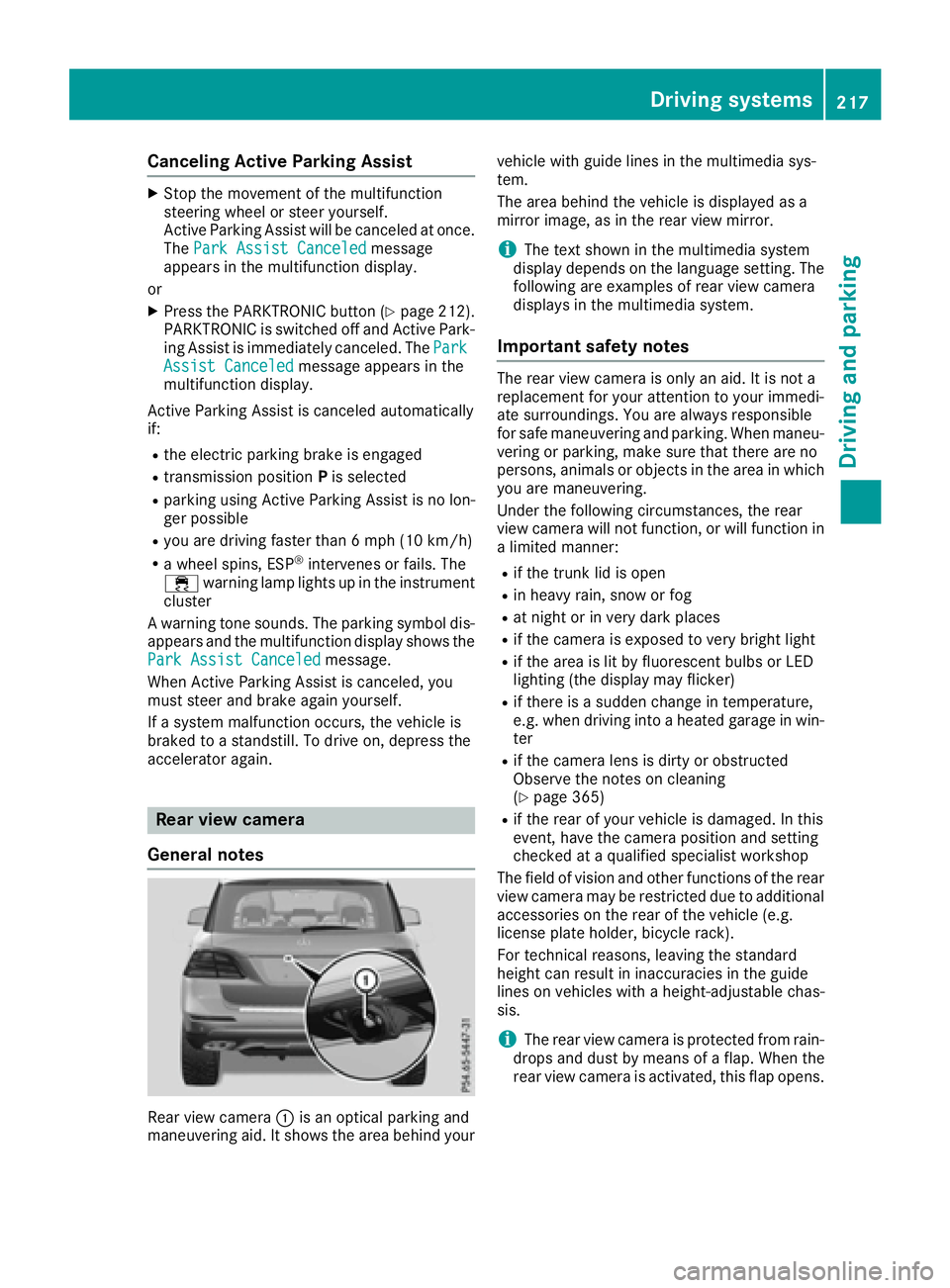
Rear view camera :is an optical parking and
maneuvering aid. It shows the area behind your vehicle with guide lines in the multimedia sys-
tem.
The area behind the vehicle is displayed as a
mirror image, as in the rear view mirror.
iThe text shown in the multimedia system
display depends on the language setting. The
following are examples of rear view camera
displays in the multimedia system.
Important safety notes
The rear view camera is only an aid. It is not a
replacement for your attention to your immedi-
ate surroundings. You are always responsible
for safe maneuvering and parking. When maneu-
vering or parking, make sure that there are no
persons, animals or objects in the area in which you are maneuvering.
Under the following circumstances, the rear
view camera will not function, or will function in
a limited manner:
Rif the trunk lid is open
Rin heavy rain, snow or fog
Rat night or in very dark places
Rif the camera is exposed to very bright light
Rif the area is lit by fluorescent bulbs or LED
lighting (the display may flicker)
Rif there is a sudden change in temperature,
e.g. when driving into a heated garage in win- ter
Rif the camera lens is dirty or obstructed
Observe the notes on cleaning
(
Ypage 365)
Rif the rear of your vehicle is damaged. In this
event, have the camera position and setting
checked at a qualified specialist workshop
The field of vision and other functions of the rear
view camera may be restricted due to additional
accessories on the rear of the vehicle (e.g.
license plate holder, bicycle rack).
For technical reasons, leaving the standard
height can result in inaccuracies in the guide
lines on vehicles with a height-adjustable chas-
sis.
iThe rear view camera is protected from rain-
drops and dust by means of a flap. When the
rear view camera is activated, this flap opens.
Driving systems217
Driving and parking
Z
Page 224 of 450
Rif the camera lenses are dirty or covered
Rif the vehicle components in which the cam-
eras are installed are damaged. In this event,
have the camera position and setting checked
at a qualified specialist workshop
Do not use the 360° camera in this case. You
can otherwise injure others or cause damage to objects or the vehicle.
Guide lines are always shown at road level.
The field of vision and other functions of the
camera system may be restricted due to addi-
tional accessories on the rear of the vehicle (e.g.
license plate holder, bicycle rack).
On vehicles with height-adjustable chassis,
depending on technical conditions, leaving the
standard height can result in:
Rinaccuracies in the guide lines
Rinaccuracies in the display of generated
images (top view)
Activation conditions
The 360° camera image can be displayed if:
Ryour vehicle is equipped with a 360° camera
Rthe SmartKey is in position 2in the ignition
lock
Rthe multimedia system is switched on
Switching on the 360° camera
XPress the Øbutton in the center console
for longer than two seconds.
Depending on whether position Dor Ris
engaged, the following is shown:
Ra split screen with top view and the image
from the front camera or
Ra split screen with top view and the image
from the rear view camera
or
XPress the Øbutton in the center console.
The vehicle menu is displayed.
XSelect 360°Cameraand press 7to confirm.
Depending on whether position Dor Ris
engaged, the following is shown:
Ra split screen with top view and the image
from the front camera or
Ra split screen with top view and the image
from the rear view camera
Activating the 360° camera using
reverse gear
The 360° camera images can be automatically
displayed by engaging reverse gear.
XMake sure that the SmartKey is in position 2
in the ignition lock.
XMake sure that the Activation by R gearfunction is selected in the multimedia system
(see the separate operating instructions).
XTo show the 360° camera image: engage
reverse gear.
The multimedia system shows the area
behind the vehicle in split-screen mode. You
see the top view of the vehicle and the image
from the rear view camera.
Selecting the split-screens or 180° view
Selecting split-screen view
XTo switch to the line with the vehicle icons:
slide 5the controller.
XTo select one of the vehicle icons: turn 3
the controller.
XTo switch to 180° View:turn 3 the con-
troller to select 180° View
and press7to
confirm.
iThe 180°Viewoption is only available in the
following views:
RTop view with picture from the rear view
camera
RTop view with picture from the front camera
Displays in the multimedia system
Important safety notes
The camera system may show a distorted view
of obstacles, show them incorrectly or not at all.
Obstacles are not shown by the system in the
following locations:
Runder the front and rear bumpers
Rvery close to the front and rear bumpers
Rin the area immediately above the tailgate
handle
Rvery close to the exterior mirrors
Rin the transitional areas between the various
cameras in the virtual top view
222Driving systems
Driving and parking
Page 259 of 450
The applicable permissible values, which must
not be exceeded, can be found:
Rin the vehicle documents
Ron the identification plates for the trailer tow
hitch and the trailer
Ron the vehicle identification plate
If the values differ, the lowest value applies.
When towing a trailer, your vehicle's handling
characteristics will be different in comparison
with when driving without a trailer.
The vehicle/trailer combination:
Ris heavier
Ris restricted in its acceleration and gradient-
climbing capability
Rhas an increased braking distance
Ris affected more by strong crosswinds
Rdemands more sensitive steering
Rhas a larger turning circle
This could impair the handling characteristics.
When towing a trailer, always adjust your speed
to the current road and weather conditions. Do
not exceed the maximum permissible speed for
your vehicle/trailer combination.
Notes on towing a trailer
General notes
The GLE 550 e 4MATIC cannot be used to tow a
trailer.
RDo not exceed the legally prescribed maxi-
mum speed for vehicle/trailer combinations
in the relevant country.
This lowers the risk of an accident.
ROnly install an approved trailer coupling on
your vehicle.
Further information on availability and on
installation is available from any authorized
Mercedes-Benz Center.
RThe bumpers of your vehicle are not suitable
for installing detachable trailer couplings.
RDo not install hired trailer couplings or other
detachable trailer couplings on the bumpers
of your vehicle.
RIf you no longer need the ball coupling,
remove it from the ball coupling recess. This
will reduce the risk of damage to the ball cou-
pling. When towing a trailer, set the tire pressure on
the rear axle of the towing vehicle for the max-
imum load. You will find the values in the tire
pressure table in the fuel filler flap of the vehicle
(
Ypage 406).
Please note that when towing a trailer, the fol-
lowing driving systems have limited availability
or are not available at all:
RPARKTRONIC (Ypage 210)
RBlind Spot Assist (Ypage 227)
RActive Lane Keeping Assist (Ypage 233)
On vehicles without level control, the height of
the ball coupling will alter according to the load
placed on the vehicle. If necessary, use a trailer
with a height-adjustable drawbar.
You will find installing dimensions and loads
under "Technical data" (
Ypage 444).
Driving tips
Observe the information on ESP®trailer stabili-
zation (Ypage 73) and on pulling away with a
trailer (Ypage 149).
The maximum permissible speed for vehicle/
trailer combinations depends on the type of
trailer. Before beginning the journey, check the
trailer's documents to see what the maximum
permissible speed is. Observe the legally pre-
scribed maximum speed in the relevant country.
For certain Mercedes-Benz vehicles, the maxi-
mum permissible rear axle load is increased
when towing a trailer. See "Technical data" to
find out whether this applies to your vehicle
(
Ypage 445). If you utilize any of the added
maximum rear axle load when towing a trailer,
the vehicle/trailer combination may not exceed
a maximum speed of 60 mph (100 km/ h)for
reasons concerning the operating permit. This
also applies in countries in which the permissi-
ble maximum speed for vehicle/trailer combi-
nations is above 60 mph (100 km/h).
When towing a trailer, your vehicle's handling
characteristics will be different in comparison
with when driving without a trailer.
Use the left-hand steering wheel paddle shifter
to shift into a lower gear in good time on long
and steep downhill gradients.
This also applies if you have activated cruise
control or DISTRONIC PLUS.
This will use the braking effect of the engine, so that less braking will be required to maintain the
speed. This relieves the load on the brake sys-
Towing a trailer257
Driving and parking
Z
Page 359 of 450
!Make sure that the windshield wipers are
not folded away from the windshield. You
could otherwise damage the windshield wip-
ers or the hood.
XMake sure that the windshield wipers are
turned off.
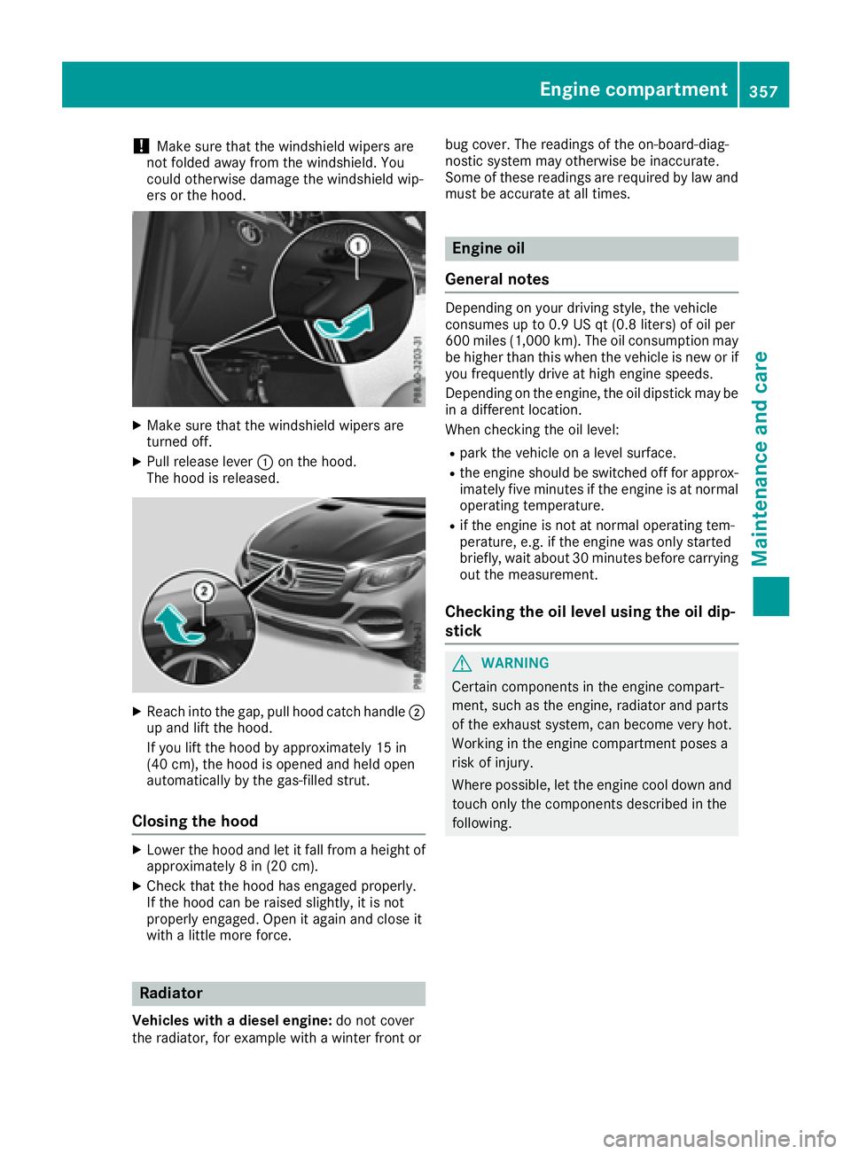
XPull release lever :on the hood.
The hood is released.
XReach into the gap, pull hood catch handle ;
up and lift the hood.
If you lift the hood by approximately 15 in
(40 cm), the hood is opened and held open
automatically by the gas-filled strut.
Closing the hood
XLower the hood and let it fall from a height of
approximately 8 in (20 cm).
XCheck that the hood has engaged properly.
If the hood can be raised slightly, it is not
properly engaged. Open it again and close it
with a little more force.
Radiator
Vehicles with a diesel engine: do not cover
the radiator, for example with a winter front or bug cover. The readings of the on-board-diag-
nostic system may otherwise be inaccurate.
Some of these readings are required by law and
must be accurate at all times.
Engine oil
General notes
Depending on your driving style, the vehicle
consumes up to 0.9 US qt (0.8 liters) of oil per
600 miles (1,000 km). The oil consumption may
be higher than this when the vehicle is new or if
you frequently drive at high engine speeds.
Depending on the engine, the oil dipstick may be
in a different location.
When checking the oil level:
Rpark the vehicle on a level surface.
Rthe engine should be switched off for approx-
imately five minutes if the engine is at normal
operating temperature.
Rif the engine is not at normal operating tem-
perature, e.g. if the engine was only started
briefly, wait about 30 minutes before carrying
out the measurement.
Checking the oil level using the oil dip-
stick
GWARNING
Certain components in the engine compart-
ment, such as the engine, radiator and parts
of the exhaust system, can become very hot.
Working in the engine compartment poses a
risk of injury.
Where possible, let the engine cool down and touch only the components described in the
following.
Engine compartment357
Maintenance and care
Z
Page 392 of 450
Once the winter tires are mounted:
XCheck the tire pressures (Ypage 393).
XRestart the tire pressure monitor
(Ypage 394).
XVehicles for Canada:restart the tire pres-
sure loss warning system (Ypage 394).
Information about driving with an emergency
spare wheel (
Ypage 426).
Snow chains
GWARNING
If snow chains are installed to the front
wheels, they may drag against the vehicle
body or chassis components. This could
cause damage to the vehicle or the tires.
There is a risk of an accident.
To avoid hazardous situations:
Rnever install snow chains to the front
wheels
Ralways install snow chains in pairs to the
rear wheels.
!You must drive at raised vehicle level (height
1) if snow chains have been installed. The
vehicle may otherwise be damaged.
!Vehicles with ADS (Adaptive Damping
System): do not use the sport mode when
driving with snow chains mounted. The vehi-
cle may otherwise be damaged.
!On some tire sizes there is not enough space
for snow chains. To avoid damage to the vehi-
cle or tires, observe the "Wheel and tire com-
binations" section under "Tires and wheels".
For safety reasons, Mercedes-Benz recom-
mends that you only use snow chains that have
been specially approved for your vehicle by
Mercedes-Benz, or are of a corresponding
standard of quality. For more information,
please contact a qualified specialist workshop.
If you intend to mount snow chains, please bear
the following points in mind:
ROnly use snow chains when driving on roads
completely covered by snow. Remove the snow chains as soon as possible when you
come to a road that is not snow-covered.
Rdo not exceed the maximum permissible
speed of 30 mph (50 km/h).
RLocal regulations may restrict the use of snow
chains. Observe the appropriate regulations if
you wish to mount snow chains.
RSnow chains may not be mounted on all
wheel/tire combinations. Permissible wheel-
tire combinations (
Ypage 413).
You may wish to deactivate ESP®when pulling
away with snow chains installed (Ypage 72).
You can thereby allow the wheels to spin in a
controlled manner, achieving an increased driv-
ing force (cutting action).
Information about driving with an emergency
spare wheel (
Ypage 426).
Tire pressure
Tire pressure specifications
Important safety notes
GWARNING
Underinflated or overinflated tires pose the
following risks:
Rthe tires may burst, especially as the load
and vehicle speed increase.
Rthe tires may wear excessively and/or
unevenly, which may greatly impair tire
traction.
Rthe driving characteristics, as well as steer-
ing and braking, may be greatly impaired.
There is a risk of an accident.
Follow recommended tire inflation pressures
and check the pressure of all the tires includ-
ing the spare wheel:
Rmonthly, at least
Rif the load changes
Rbefore beginning a long journey
Runder different operating conditions, e.g.
off-road driving
If necessary, correct the tire pressure.
The data on the Tire and Loading Information
placard and tire pressure table shown here are
390Tire pressure
Wheels and tires
Page 405 of 450
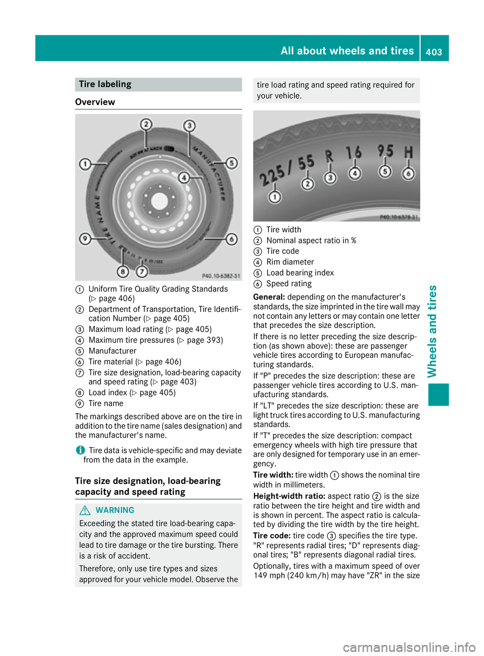
Tire labeling
Overview
:Uniform Tire Quality Grading Standards
(Ypage 406)
;Department of Transportation, Tire Identifi-
cation Number (Ypage 405)
=Maximum load rating (Ypage 405)
?Maximum tire pressures (Ypage 393)
AManufacturer
BTire material (Ypage 406)
CTire size designation, load-bearing capacity
and speed rating (Ypage 403)
DLoad index (Ypage 405)
ETire name
The markings described above are on the tire in
addition to the tire name (sales designation) and
the manufacturer's name.
iTire data is vehicle-specific and may deviate
from the data in the example.
Tire size designation, load-bearing
capacity and speed rating
GWARNING
Exceeding the stated tire load-bearing capa-
city and the approved maximum speed could
lead to tire damage or the tire bursting. There is a risk of accident.
Therefore, only use tire types and sizes
approved for your vehicle model. Observe the
tire load rating and speed rating required for
your vehicle.
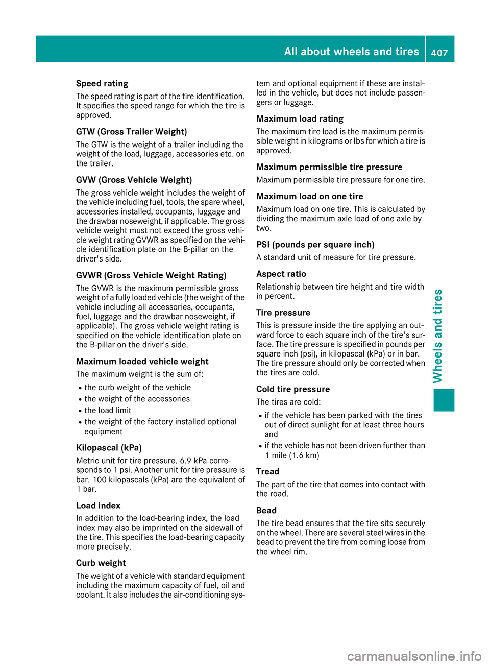
:Tire width
;Nominal aspect ratio in %
=Tire code
?Rim diameter
ALoad bearing index
BSpeed rating
General: depending on the manufacturer's
standards, the size imprinted in the tire wall may
not contain any letters or may contain one letter
that precedes the size description.
If there is no letter preceding the size descrip-
tion (as shown above): these are passenger
vehicle tires according to European manufac-
turing standards.
If "P" precedes the size description: these are
passenger vehicle tires according to U.S. man-
ufacturing standards.
If "LT" precedes the size description: these are
light truck tires according to U.S. manufacturing
standards.
If "T" precedes the size description: compact
emergency wheels with high tire pressure that
are only designed for temporary use in an emer-
gency.
Tire width: tire width:shows the nominal tire
width in millimeters.
Height-width ratio: aspect ratio;is the size
ratio between the tire height and tire width and
is shown in percent. The aspect ratio is calcula-
ted by dividing the tire width by the tire height.
Tire code: tire code=specifies the tire type.
"R" represents radial tires; "D" represents diag-
onal tires
; "B" represents diagonal radial tires.
Optionally, tires with a maximum speed of over
149 mph (240 km/h) may have "ZR" in the size
All about wheels an d tires403
Wheels and tires
Z
Page 409 of 450
Speed rating
The speed rating is part of the tire identification.It specifies the speed range for which the tire is
approved.
GTW (Gross Trailer Weight)
The GTW is the weight of a trailer including the
weight of the load, luggage, accessories etc. on
the trailer.
GVW (Gross Vehicle Weight)
The gross vehicle weight includes the weight of
the vehicle including fuel, tools, the spare wheel,
accessories installed, occupants, luggage and
the drawbar noseweight, if applicable. The gross
vehicle weight must not exceed the gross vehi-
cle weight rating GVWR as specified on the vehi- cle identification plate on the B-pillar on the
driver's side.
GVWR (Gross Vehicle Weight Rating)
The GVWR is the maximum permissible gross
weight of a fully loaded vehicle (the weight of the
vehicle including all accessories, occupants,
fuel, luggage and the drawbar noseweight, if
applicable). The gross vehicle weight rating is
specified on the vehicle identification plate on
the B-pillar on the driver's side.
Maximum loaded vehicle weight
The maximum weight is the sum of:
Rthe curb weight of the vehicle
Rthe weight of the accessories
Rthe load limit
Rthe weight of the factory installed optional
equipment
Kilopascal (kPa)
Metric unit for tire pressure. 6.9 kPa corre-
sponds to 1 psi. Another unit for tire pressure is
bar. 100 kilopascals (kPa) are the equivalent of
1 bar.
Load index
In addition to the load-bearing index, the load
index may also be imprinted on the sidewall of
the tire. This specifies the load-bearing capacity
more precisely.
Curb weight
The weight of a vehicle with standard equipment
including the maximum capacity of fuel, oil and
coolant. It also includes the air-conditioning sys- tem and optional equipment if these are instal-
led in the vehicle, but does not include passen-
gers or luggage.
Maximum load rating
The maximum tire load is the maximum permis-
sible weight in kilograms or lbs for which a tire is approved.
Maximum permissible tire pressure
Maximum permissible tire pressure for one tire.
Maximum load on one tire
Maximum load on one tire. This is calculated by
dividing the maximum axle load of one axle by
two.
PSI (pounds per square inch)
A standard unit of measure for tire pressure.
Aspect ratio
Relationship between tire height and tire widt h
in percent.
Tire pressure
This is pressure inside the tire applying an out-
ward force to each square inch of the tire's sur-
face. The tire pressure is specified in pounds per
square inch (psi), in kilopascal (kPa) or in bar.
The tire pressure should only be corrected when the tires are cold.
Cold tire pressure
The tires are cold:
Rif the vehicle has been parked with the tires
out of direct sunlight for at least three hours
and
Rif the vehicle has not been driven further than
1 mile (1.6 km)
Tread
The part of the tire that comes into contact with
the road.
Bead
The tire bead ensures that the tire sits securely
on the wheel. There are several steel wires in the
bead to prevent the tire from coming loose from
the wheel rim.
All about wheels and tires407
Wheels and tires
Z