flat tire MERCEDES-BENZ GLE COUPE 2015 Owners Manual
[x] Cancel search | Manufacturer: MERCEDES-BENZ, Model Year: 2015, Model line: GLE COUPE, Model: MERCEDES-BENZ GLE COUPE 2015Pages: 393, PDF Size: 12.71 MB
Page 13 of 393
ESP
®
(Electronic Stability Pro-
gram)
AMG menu (on-board computer) .. .250
Characteristics ................................. 70
Deactivating/activating ................... 70
Display message ............................ 254
Function/notes ................................ 69
General notes .................................. 69
Important safety guidelines ............. 70
Trailer stabilisatio n.......................... 71
Warning lamp ................................. 291
ETS/4ETS (Electronic Traction Sys-
tem) ...................................................... 70
Exhaust pipe (cleaning instruc-
tions) .................................................. 328
Exterior mirrors
Adjusting ....................................... 111
Anti-dazzle mode (automatic) ........ 112
Folding in when locking (on-board computer) ...................................... 249
Folding in/out (automatically )....... 112
Folding in/out (electrically) ........... 112
Out of position (troubleshooting) ... 112
Parking position ............................. 113
Resetting ....................................... 112
Storing settings (memory func-
tion) ............................................... 114 F
Fault message see Display messages
Filler cap
see Fuel filler flap
Fire extinguisher ............................... 332
First-aid kit ......................................... 331
Fitting a wheel
Fitting a wheel ............................... 359
Lowering the vehicle ...................... 360
Preparing the vehicle ..................... 357
Raising the vehicl e......................... 358
Removing a whee l.......................... 359
Securing the vehicle against roll-
ing away ........................................ 357
Flat tyre
MOExtended tyre s......................... 333
Preparing the vehicle ..................... 333
TIREFIT kit ...................................... 334 see Emergency spare wheel
Floormat ............................................. 316
Foglamps (extended range) .............. 119
Folding the rear bench seat for-
wards/back ....................................... 302
Fording
Off-road ......................................... 174
On flooded roads ........................... 174
Frequencies
Garage door opener ....................... 314
Mobile phone ................................. 372
Two-way radio ................................ 372
Front-passenger front airbag deac-
tivation
Display message ............................ 264
Front-passenger front airbag deac-
tivation system
Operation ......................................... 45
Problems ......................................... 49
System self-test ............................... 47
Fuel
Additives ........................................ 376
Consumption information .............. 377
Consumption statistics .................. 238
Displaying the current consump-
tion ................................................ 239
Displaying the range ...................... 239
Driving tip s.................................... 171
Fuel gauge ....................................... 29
Grade (petrol) ................................ 375
Important safety notes .................. 375
Low outside temperatures ............. 377
Notes for Mercedes ‑AMG vehi-
cles ................................................ 376
Problem (malfunction) ................... 164
Quality (diesel )............................... 376
Refuelling ....................................... 161
Tank content/reserve fue l............. 375
Fuel filler flap
Opening ......................................... 162
Fuel filter (white display message) .. 271
Fuel level
Calling up the range (on-board
computer) ...................................... 239
Gauge .............................................. 29
Fuel tank
Capacity ........................................ 375 10
Index
Page 22 of 393
Trailer coupling
see Towing a trailer
Trailer towing
7-pin connector ............................. 232
Blind Spot Assist ............................ 220
Cleaning the trailer tow hitch ......... 328
Coupling up a traile r...................... 229
Decoupling a trailer ....................... 230
Driving tips .................................... 227
Important safety notes .................. 226
Lights display message .................. 266
Mounting dimensions .................... 384
Parktronic ...................................... 199
Power supply ................................. 232
Problem (fault) ............................... 233
Trailer load s................................... 385
Transmission
see Automatic transmission
Transmission position display ......... 154
Transmission position display
(DIRECT SELECT lever) ...................... 154
Transporting the vehicle .................. 345
Travelling uphill
Brow of hill ..................................... 178
Driving downhill ............................. 178
Maximum gradient-climbing capa-
bility ............................................... 178
Trim pieces (cleaning instruc-
tions) .................................................. 329
Trip computer (on-board com-
puter) .................................................. 238
Trip meter
Calling up ....................................... 238
Resetting (on-board computer) ...... 239
Turn signals
Switching on/of f........................... 117
TV
Operating (on-board computer) ..... 242
see Separate operating instructions
Two-way radio
Frequencies ................................... 372
Installation ..................................... 372
Transmission output (maximum) .... 372
Type identification plate
see Vehicle identification plate
Tyre changing tool kit ....................... 332Tyre inflation compressor
see TIREFIT kit
Tyre pressure
Calling up (on-board computer) ..... 354
Display message ............................ 279
Not reached (TIREFIT) .................... 336
Reached (TIREFIT) .......................... 336
Recommended ............................... 351
Tyre pressure loss warning
General notes ................................ 353
Important safety notes .................. 353
Restarting ...................................... 353
Tyre pressure monitor
Checking the tyre pressure elec-
tronically ........................................ 354
Function/note s............................. 354
General notes ................................ 354
Important safety notes .................. 354
Radio type approval for the tyre
pressure monitor ........................... 356
Restarting ...................................... 355
Warning lamp ................................. 298
Warning message .......................... 355
Tyres
Changing a whee l.......................... 356
Checking ........................................ 349
Direction of rotation ...................... 357
Display message ............................ 279
General notes ................................ 361
Important safety notes .................. 348
Information on driving .................... 348
M+S tyres ...................................... 350
MOExtended tyre s......................... 350
Replacing ....................................... 356
Service life ..................................... 349
Storing ........................................... 357
Tyre size (data ).............................. 361
Tyre tread ...................................... 349
Wheel and tyre combinations ........ 362
see Flat tyre U
Unlocking Emergency unlocking ....................... 86
From inside the vehicle (central
unlocking button) ............................. 85 Index
19
Page 60 of 393
Rearward-facing child restraint system
If it is absolutely necessary to fit a rearward-
facing child restraint system to the front-
passenger seat, always make sure that the
front-passenger front airbag is disabled. Only if
the PASSENGER AIR BAG OFF indicator lamp is
lit continuously (Y page 38) is the front-
passenger front airbag disabled.
Always observe the information on suitable
positioning of the child restraint system
(Y page 57) in addition to the child restraint
system manufacturer's installation and operat-
ing instructions.
Forward-facing child restraint system If it is absolutely necessary to fit a forward-
facing child restraint system to the front-
passenger seat, always move the front-
passenger seat as far back as possible. The
entire base of the child restraint system must
always rest on the seat cushion of the front-
passenger seat. The backrest of the child
restraint system must, as far as possible, lie flat
against the backrest of the front-passenger
seat. The child restraint system must not touch the roof or be put under strain by the head
restraint. Adjust the angle of the seat backrest
and the head restraint position accordingly.
Always make sure that the shoulder belt strap is
correctly routed from the vehicle belt outlet to
the shoulder belt guide on the child restraint
system. The shoulder belt strap must be routed forwards and downwards from the vehicle belt
outlet. If necessary, adjust the vehicle belt out-
let and the front-passenger seat accordingly.
Always observe the information on suitable
positioning of the child restraint system
(Y page 57) in addition to the child restraint
system manufacturer's installation and operat-
ing instructions. Suitable positioning of the child
restraint system
Introduction Only child restraint systems which are approved
in accordance with the ECE standard ECE R44
are permitted for use in the vehicle.
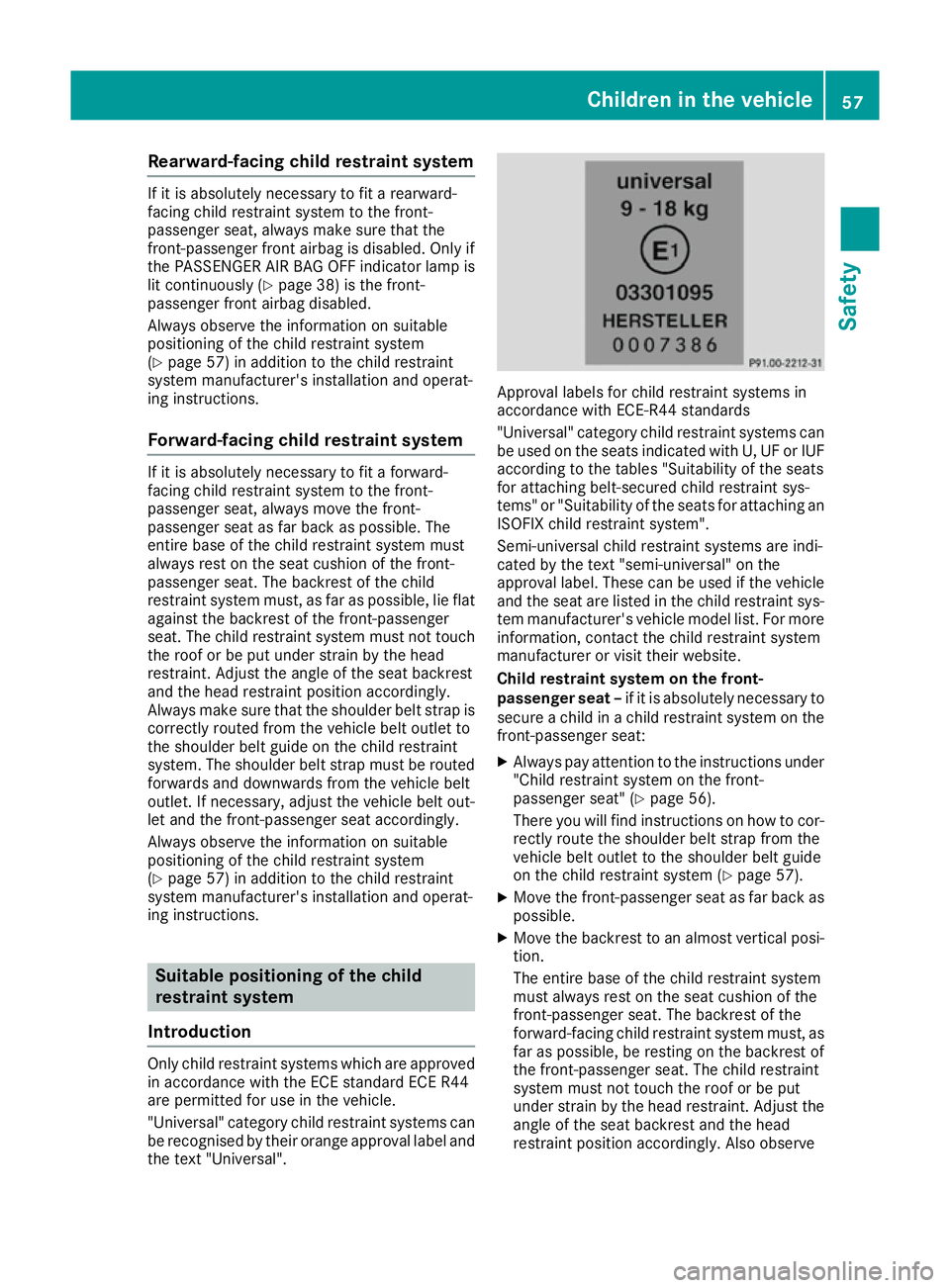
"Universal" category child restraint systems can
be recognised by their orange approval label and the text "Universal". Approval labels for child restraint systems in
accordance with ECE-R44 standards
"Universal" category child restraint systems can
be used on the seats indicated with U, UF or IUF according to the tables "Suitability of the seats
for attaching belt-secured child restraint sys-
tems" or "Suitability of the seats for attaching an
ISOFIX child restraint system".
Semi-universal child restraint systems are indi-
cated by the text "semi-universal" on the
approval label. These can be used if the vehicle and the seat are listed in the child restraint sys-
tem manufacturer's vehicle model list. For more
information, contact the child restraint system
manufacturer or visit their website.
Child restraint system on the front-
passenger seat – if it is absolutely necessary to
secure a child in a child restraint system on the front-passenger seat:
X Always pay attention to the instructions under
"Child restraint system on the front-
passenger seat" (Y page 56).
There you will find instructions on how to cor- rectly route the shoulder belt strap from the
vehicle belt outlet to the shoulder belt guide
on the child restraint system (Y page 57).
X Move the front-passenger seat as far back as
possible.
X Move the backrest to an almost vertical posi-
tion.
The entire base of the child restraint system
must always rest on the seat cushion of the
front-passenger seat. The backrest of the
forward-facing child restraint system must, as far as possible, be resting on the backrest of
the front-passenger seat. The child restraint
system must not touch the roof or be put
under strain by the head restraint. Adjust the
angle of the seat backrest and the head
restraint position accordingly. Also observe Children in the vehicle
57Safety Z
Page 335 of 393
Fire extinguisher
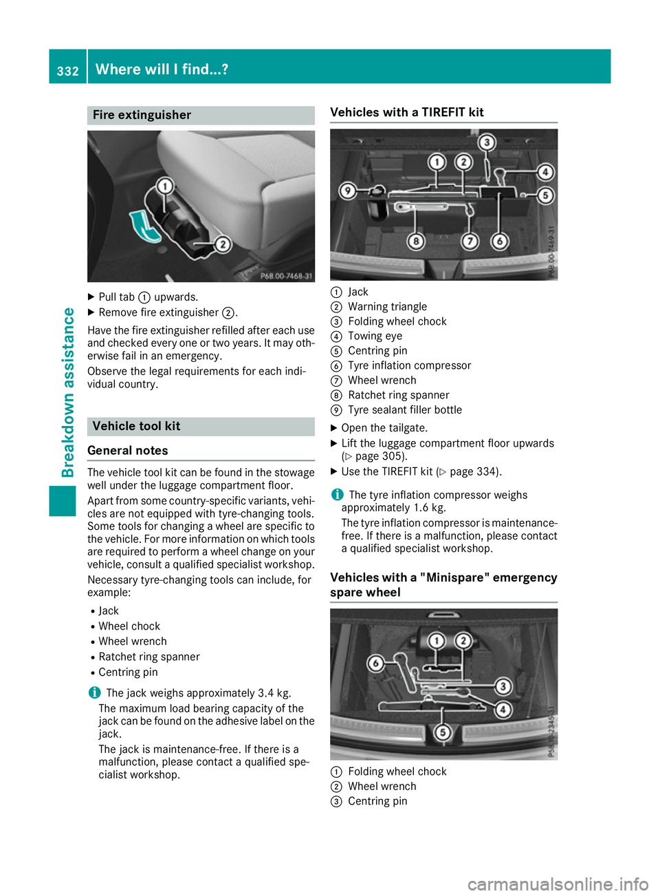
X
Pull tab :upwards.
X Remove fire extinguisher ;.
Have the fire extinguisher refilled after each use and checked every one or two years. It may oth-
erwise fail in an emergency.
Observe the legal requirements for each indi-
vidual country. Vehicle tool kit
General notes The vehicle tool kit can be found in the stowage
well under the luggage compartment floor.
Apart from some country-specific variants, vehi-
cles are not equipped with tyre-changing tools.
Some tools for changing a wheel are specific to the vehicle. For more information on which tools
are required to perform a wheel change on your
vehicle, consult a qualified specialist workshop.
Necessary tyre-changing tools can include, for
example:
R Jack
R Wheel chock
R Wheel wrench
R Ratchet ring spanner
R Centring pin
i The jack weighs approximately 3.4 kg.
The maximum load bearing capacity of the
jack can be found on the adhesive label on the jack.
The jack is maintenance-free. If there is a
malfunction, please contact a qualified spe-
cialist workshop. Vehicles with a TIREFIT kit
:
Jack
; Warning triangle
= Folding wheel chock
? Towing eye
A Centring pin
B Tyre inflation compressor
C Wheel wrench
D Ratchet ring spanner
E Tyre sealant filler bottle
X Open the tailgate.
X Lift the luggage compartment floor upwards
(Y page 305).
X Use the TIREFIT kit (Y page 334).
i The tyre inflation compressor weighs
approximately 1.6 kg.
The tyre inflation compressor is maintenance-
free. If there is a malfunction, please contact a qualified specialist workshop.
Vehicles with a "Minispare" emergency
spare wheel :
Folding wheel chock
; Wheel wrench
= Centring pin 332
Where will I find...?Breakdown assistance
Page 336 of 393

?
Towing eye
A Jack
B Ratchet ring spanner
X Open the tailgate.
X Lift the luggage compartment floor upwards
(Y page 305).
X Remove the "Minispare" emergency spare
wheel (Y page 368). Flat tyre
Preparing the vehicle
Your vehicle may be equipped with: R MOExtended tyres (tyres with run-flat char-
acteristics)
Vehicle preparation is not necessary on vehi- cles with MOExtended tyres.
R a TIREFIT kit (Y page 332)
R an emergency spare wheel (certain countries
only)
Information on changing and fitting a wheel
(Y page 356).
X Stop the vehicle as far away as possible from
traffic on solid, non-slippery and level ground.
X Switch on the hazard warning lamps.
X Safeguard the vehicle against rolling away
(Y page 167).
X If possible, bring the front wheels into the
straight-ahead position.
X Vehicles with the AIRMATIC package:
make sure that the normal vehicle level is
selected (Y page 196).
X Switch off the engine.
X Vehicles without KEYLESS-GO: remove the
key from the ignition lock.
X Vehicles with KEYLESS-GO: open the driv-
er's door.
The on-board electronics now have status 0.
This is the same as the key having been
removed.
X Vehicles with KEYLESS-GO: remove the
Start/Stop button from the ignition lock
(Y page 146).
X Make sure that the passengers are not endan-
gered as they do so. Make sure that no one is
near the danger area while a wheel is being
changed. Anyone who is not directly assisting in the wheel change should, for example,
stand behind the barrier.
X Get out of the vehicle. Pay attention to traffic
conditions when doing so.
X Close the driver's door.
X Place the warning triangle at a suitable dis-
tance (Y page 331). Observe legal require-
ments.
i Only operate the tyre inflation compressor
using a 12 V socket, even if the ignition is
turned off (Y page 309).
An emergency cut-off ensures that the on-
board voltage does not drop too low. If the on-
board voltage is too low, the power to the
sockets is automatically cut. This ensures
that there is sufficient power to start the
engine. MOExtended tyres (tyres with run-flat
characteristics)
General notes With MOExtended tyres (tyres with run-flat char-
acteristics), you can continue to drive your vehi-
cle even if there is a total loss of pressure in one or more tyres. The affected tyre must not show
any clearly visible damage.
You can recognise MOExtended tyres by the
MOExtended marking which appears on the tyre
wall. You will find this marking next to the tyre
size designation, the load-bearing capacity and
the speed index.
MOExtended tyres may only be used in conjunc- tion with an activated tyre pressure loss warning
system or tyre pressure monitor.
If a pressure loss warning message appears in the multifunction display:
R observe the instructions in the display mes-
sages (Y page 279)
R check the tyre for damage
R if driving on, observe the following notes
The driving distance possible in run-flat mode is approximately 80 km when the vehicle is parti-
ally laden and approximately 30 km when the
vehicle is fully laden. Flat tyre
333Breakdown assistance
Page 337 of 393

In addition to the vehicle load, the driving dis-
tance possible depends upon:
R vehicle speed
R road condition
R outside temperature
The driving distance possible in run-flat mode
may be reduced by extreme driving conditions/
manoeuvres, or it can be increased through a
moderate style of driving.
The driving distance possible in run-flat mode is counted from the moment the tyre pressure loss
warning appears in the multifunction display.
You must not exceed a maximum speed of
80 km/h.
When replacing one or all tyres, observe the fol-
lowing specifications for your vehicle's tyres:
R size
R type and
R the "MOExtended" mark
Vehicles with MOExtended tyres are not equip-
ped with a TIREFIT kit at the factory. It is there-
fore recommended that you additionally equip
your vehicle with a TIREFIT kit if you fit tyres that do not feature run-flat characteristics, e.g. win-
ter tyres. A TIREFIT kit can be obtained from a
qualified specialist workshop.
Important safety notes G
WARNING
When driving in emergency mode, the driving characteristics deteriorate, e.g. when corner-
ing, accelerating quickly and when braking.
There is a risk of accident.
Do not exceed the stated maximum speed.
Avoid abrupt steering and driving manoeu-
vres, and driving over obstacles (kerbs, pot-
holes, off-road). This applies in particular to a laden vehicle.
Stop driving in emergency mode if:
R you hear banging noises.
R the vehicle starts to shake.
R you see smoke and smell rubber.
R ESP ®
is intervening constantly.
R there are tears in the sidewalls of the tyre.
After driving in emergency mode, have the
wheel rims checked at a qualified specialist workshop with regard to their further use. The
faulty tyre must be replaced. TIREFIT kit
Important safety notes TIREFIT is a tyre sealant.
You can use TIREFIT to seal punctures of up to
4 mm, particularly those in the tyre tread. You
can use TIREFIT at outside temperatures down
to Ò20 †. G
WARNING
In the following situations, the tyre sealant is
unable to provide sufficient breakdown assis- tance, as it is unable to seal the tyre properly:
R there are cuts or punctures in the tyre
larger than those mentioned above.
R the wheel rim is damaged.
R you have driven at very low tyre pressures
or on a flat tyre.
There is a risk of an accident.
Do not drive any further. Contact a qualified
specialist workshop. G
WARNING
The tyre sealant is harmful and causes irrita-
tion. It must not come into contact with your
skin, eyes or clothing or be swallowed. Do not inhale TIREFIT fumes. Keep tyre sealant away
from children. There is a risk of injury.
If you come into contact with the tyre sealant,
observe the following:
R Rinse off the tyre sealant from your skin
immediately with water.
R If the tyre sealant comes into contact with
your eyes, immediately rinse them thor-
oughly with clean water.
R If tyre sealant is swallowed, immediately
rinse your mouth out thoroughly and drink
plenty of water. Do not induce vomiting,
and seek medical attention immediately. 334
Flat tyreBreakdown assistance
Page 338 of 393
R
Immediately change out of clothing which
has come into contact with tyre sealant.
R If an allergic reaction occurs, seek medical
attention immediately.
! Do not operate the tyre inflation compres-
sor for longer than eight minutes at a time
without a break. It may otherwise overheat.
The tyre inflation compressor can be oper-
ated again once it has cooled down.
Comply with the manufacturer's safety instruc-
tions on the sticker on the tyre inflation com-
pressor.
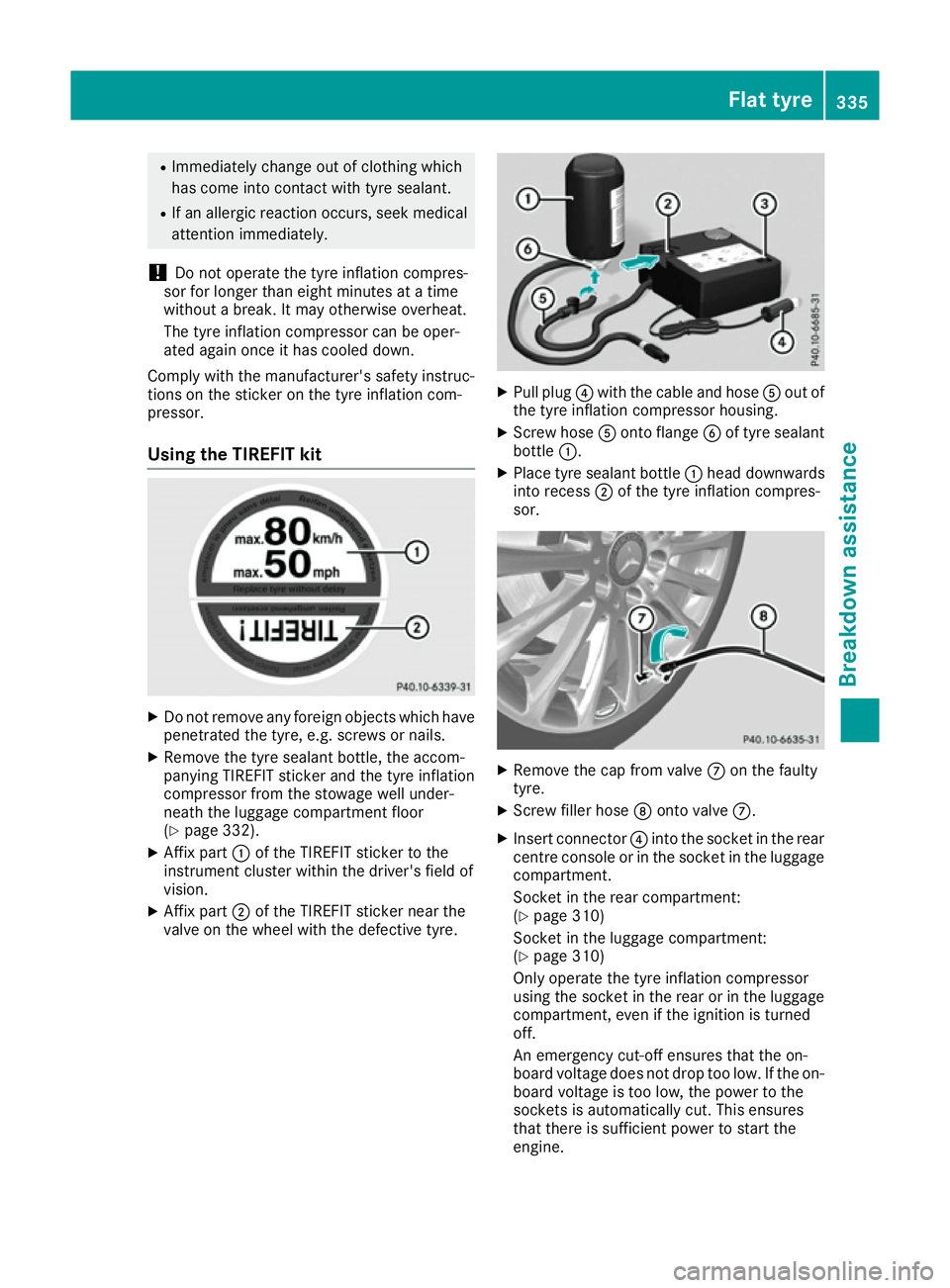
Using the TIREFIT kit X
Do not remove any foreign objects which have
penetrated the tyre, e.g. screws or nails.
X Remove the tyre sealant bottle, the accom-
panying TIREFIT sticker and the tyre inflation
compressor from the stowage well under-
neath the luggage compartment floor
(Y page 332).
X Affix part :of the TIREFIT sticker to the
instrument cluster within the driver's field of
vision.
X Affix part ;of the TIREFIT sticker near the
valve on the wheel with the defective tyre. X
Pull plug ?with the cable and hose Aout of
the tyre inflation compressor housing.
X Screw hose Aonto flange Bof tyre sealant
bottle :.
X Place tyre sealant bottle :head downwards
into recess ;of the tyre inflation compres-
sor. X
Remove the cap from valve Con the faulty
tyre.
X Screw filler hose Donto valve C.
X Insert connector ?into the socket in the rear
centre console or in the socket in the luggage compartment.
Socket in the rear compartment:
(Y page 310)
Socket in the luggage compartment:
(Y page 310)
Only operate the tyre inflation compressor
using the socket in the rear or in the luggage
compartment, even if the ignition is turned
off.
An emergency cut-off ensures that the on-
board voltage does not drop too low. If the on-
board voltage is too low, the power to the
sockets is automatically cut. This ensures
that there is sufficient power to start the
engine. Flat tyre
335Breakdown assistance Z
Page 339 of 393

Observe the further information on sockets
(Y page 309).
X Turn the key to position 1in the ignition lock
(Y page 146).
X Press on and off switch =on the tyre inflation
compressor to I.
The tyre inflation compressor is switched on.
The tyre is inflated.
First, tyre sealant is pumped into the tyre. The pressure may briefly rise to approximately
500 kPa (5 bar/73 psi).
Do not switch off the tyre inflation com-
pressor during this phase.
X Let the tyre inflation compressor run for a
maximum of five minutes. The tyre should
then have attained a pressure of at least
180 kPa (1.8 bar/26 psi).
If a pressure of 180 kPa (1.8 bar/26 psi) has
been attained after five minutes, see "Tyre pres-
sure reached" (Y page 336).
If a tyre pressure of 180 kPa (1.8 bar/26 psi) has
not been attained after five minutes, see "Tyre
pressure not reached" (Y page 336).
If tyre sealant leaks out, make sure you clean the affected area as quickly as possible. It is pref-
erable to use clear water.
If you get tyre sealant on your clothing, have it
cleaned as soon as possible with perchloroethy-
lene.
Tyre pressure not reached If a pressure of 180 kPa (1.8 bar/26 psi) has not
been attained after five minutes:
X Switch off the tyre inflation compressor.
X Unscrew the filler hose from the valve of the
faulty tyre.
Please note that tyre sealant may leak out
when unscrewing the filler hose.
X Very slowly drive forwards or reverse approx-
imately 10 m.
X Pump up the tyre again.
After a maximum of five minutes the tyre
pressure must be at least 180 kPa (1.8 bar/
26 psi). G
WARNING
If the required tyre pressure is not reached
after the specified time, the tyre is too badly
damaged. The tyre sealant cannot repair the
tyre in this instance. Damaged tyres and a tyre pressure that is too low can significantly
impair the vehicle's braking and driving char-
acteristics. There is a risk of accident.
Do not continue driving. Contact a qualified
specialist workshop.
Tyre pressure reached G
WARNING
A tyre temporarily sealed with tyre sealant
impairs the driving characteristics and is not
suitable for higher speeds. There is a risk of
accident.
You should therefore adapt your driving style
accordingly and drive carefully. Do not exceed the specified maximum speed with a tyre that
has been repaired using tyre sealant.
The maximum permissible speed for a tyre
sealed with tyre sealant is 80 km/h. The upper
part of the TIREFIT sticker must be affixed to the
instrument cluster where it will be easily seen by
the driver.
! After use, excess tyre sealant may run out of
the filler hose. This could cause stains.
Therefore, place the filler hose in the plastic
bag which contained the TIREFIT kit. H
Environmental note
Have the used tyre sealant bottle disposed of
professionally, e.g. at a qualified specialist
workshop.
If a tyre pressure of 180 kPa (1.8 bar/26 psi) has
been attained after five minutes:
X Switch off the tyre inflation compressor.
X Unscrew the filler hose from the valve of the
faulty tyre.
X Stow the tyre sealant bottle, the tyre inflation
compressor and the warning triangle.
X Pull away immediately.
X Stop after driving for approximately ten
minutes and check the tyre pressure with the
tyre inflation compressor.
The tyre pressure must now be at least
130 kPa (1.3 bar/19 psi). 336
Flat tyreBreakdown assistance
Page 352 of 393
Otherwise, the tyres, particularly the sidewalls,
may be damaged. Regular checking of wheels and tyres
G
WARNING
Damaged tyres can cause tyre inflation pres-
sure loss. As a result, you could lose control of your vehicle. There is a risk of accident.
Check the tyres regularly for signs of damageand replace any damaged tyres immediately.
Check wheels and tyres for damage at least
once a month. Check wheels and tyres after
driving off-road or on rough roads. Damaged
wheels can cause a loss of tyre pressure. Pay
particular attention to damage such as:
R cuts in the tyres
R punctures
R tears in the tyres
R bulges on the tyres
R deformation or severe corrosion on wheels
Regularly check the tyre tread depth and the
condition of the tread across the whole width of
the tyre (Y page 349). If necessary, turn the
front wheels to full lock in order to inspect the
inner side of the tyre surface.
All wheels must have a valve cap to protect the
valve against dirt and moisture. Do not fit any-
thing onto the valve other than the standard
valve cap or other valve caps approved for your vehicle by Mercedes-Benz. Do not fit any other
valve caps or systems, e.g. tyre pressure moni-
toring systems.
Regularly check the pressure of all the tyres,
particularly prior to long trips. Adjust the tyre
pressure as necessary (Y page 351).
Observe the notes on the emergency spare
wheel (Y page 367).
The service life of tyres depends on various fac- tors, including the following:
R driving style
R tyre pressure
R mileage Notes on the tyre tread
G
WARNING
Insufficient tyre tread will reduce tyre trac-
tion. The tyre is no longer able to dissipate
water. This means that on wet road surfaces, the risk of aquaplaning increases, in particularwhere speed is not adapted to suit the driving
conditions. There is a risk of accident.
If the tyre pressure is too high or too low, tyres may exhibit different levels of wear at differ-
ent locations on the tyre tread. Thus, you
should regularly check the tread depth and
the condition of the tread across the entire
width of all tyres.
Minimum tyre tread depth for:
R summer tyres: 3 mm
R M+S tyres: 4 mm
For safety reasons, replace the tyres before
the legally prescribed limit for the minimum
tyre tread depth is reached. Selecting, fitting and replacing tyres
G
WARNING
Exceeding the stated tyre load-bearing capa-
city and the approved maximum speed could
lead to tyre damage or the tyre bursting. There is a risk of accident.
Therefore, only use tyre types and sizes
approved for your vehicle model. Observe the
tyre load rating and speed rating required for your vehicle.
Pay special attention to country-specific
requirements for tyre approval. These require-
ments can stipulate a specific tyre type for your
vehicle. Furthermore, the use of certain tyre
types in certain regions and areas of operation
can be highly beneficial. You can find further
information regarding tyres at specialist tyre
retailers, at qualified specialist workshops or at
any Mercedes-Benz Service Centre.
R Only fit tyres and wheels of the same type and
make.
Exception: it is permissible to fit a different
type or make in the event of a flat tyre. Operation
349Wheels and tyres Z
Page 353 of 393
Observe here the "MOExtended tyres (tyres
with run-flat characteristics)" section
(Y
page 333).
R Only fit tyres of the correct size onto the
wheels.
R Run in new tyres at moderate speeds for the
first 100 km. They only reach their full per-
formance after this distance.
R Do not drive with tyres which have too little
tread depth. This otherwise significantly
reduces the traction on wet roads (aquaplan-
ing).
R Replace the tyres after six years at the latest,
regardless of wear.
Observe the notes on the emergency spare
wheel (Y page 367). MOExtended tyres (tyres with run-flat
characteristics)
With MOExtended tyres (tyres with run-flat char-
acteristics), you can continue to drive your vehi- cle even if there is a total loss of pressure in one
or more tyres.
MOExtended tyres may only be used in conjunc- tion with an activated tyre pressure loss warning
system or with an activated tyre pressure mon- itor and on wheels specifically tested by
Mercedes-Benz.
Notes on driving with MOExtended tyres with a
flat tyre (Y page 333).
i Vehicles with MOExtended tyres are not
equipped with a TIREFIT kit at the factory. It is therefore recommended that you additionally
equip your vehicle with a TIREFIT kit if you fit
tyres that do not feature run-flat characteris-
tics, e.g. winter tyres. A TIREFIT kit can be
obtained from a qualified specialist work-
shop. Winter operation
General notes
Have your vehicle winterproofed at a qualified
specialist workshop at the onset of winter.
Observe the notes in the "Changing a wheel"
section (Y page 356). Driving with summer tyres
At temperatures below +7 †, summer tyres lose
elasticity and therefore traction and braking
power. Change the tyres on your vehicle to
M+S tyres. Using summer tyres at very cold
temperatures could cause tears to form,
thereby damaging the tyres permanently.
Mercedes-Benz cannot accept responsibility for
this type of damage. G
WARNING
Damaged tyres can cause tyre inflation pres-
sure loss. As a result, you could lose control of your vehicle. There is a risk of accident.
Check the tyres regularly for signs of damageand replace any damaged tyres immediately. M+S tyres
G
WARNING
M+S tyres with a tyre tread depth of less than 4 mm are not suitable for use in winter as they
do not provide sufficient traction. There is a
risk of accident.
M+S tyres with a tread depth of less than
4 mm must be replaced.
At temperatures below +7 †, use winter tyres or all-season tyres. Both types of tyre are identified
by the M+S marking.
Only winter tyres bearing the isnowflake
symbol in addition to the M+S marking provide
the best possible grip in wintry road conditions. Only these tyres will allow driving safety sys-
tems such as ABS and ESP ®
to function opti-
mally in winter. These tyres have been devel-
oped specifically for driving in snow.
Use M+S tyres of the same make and tread on all
wheels to maintain safe handling characteris-
tics.
Always observe the maximum permissible
speed specified for the M+S tyres you have fit-
ted.
If you fit M+S tyres that have a lower maximum
permissible speed than that of the maximum
design speed of the vehicle, affix a correspond- ing warning label in the driver's field of vision.
This can be obtained at a qualified specialist
workshop. 350
Winter operationWheels and tyres