fog light MERCEDES-BENZ GLE COUPE 2021 User Guide
[x] Cancel search | Manufacturer: MERCEDES-BENZ, Model Year: 2021, Model line: GLE COUPE, Model: MERCEDES-BENZ GLE COUPE 2021Pages: 525, PDF Size: 8.83 MB
Page 234 of 525
Sy
stem limits
The sy stem may be impaired or may not function
particular lyin thefo llowing situations:
R Ifth ere is poor visibility, e.g. due toinsuf fi‐
cient illumination of thero ad, if there are
highly variable shade conditions or in rain,
sno w,fog or heavy spr ay.
R Ifth ere is glare, e.g. from oncoming traf fic,
di re ct sunlight or reflections.
R Ifth e windscreen in the area of the multi‐
function camera is dirty, or if the camera is
mis ted up, damaged or co vered.
R Ifth e tra ffic signs are hard todetect, e.g. due
to dirt, snow or insuf ficient lighting, or
because they are co vered.
R Ifth e information in the navigation sy stem's
digital map is incor rect or out-of-da te.
R Ifth e signs are ambiguous, e.g. road signs in
ro adwor ksor in adjacent lanes.
R Ifyo u turn sharply when passing traf fic signs
outside the camera's field of vision. Setting
Traf fic Sign Assist
Requ irements:
R Only vehicles with Driving Assistance
Pa ckage:
Ac tive Dis tance Assi stDISTRONIC and ECO
Assi stmust be activated forth e automatic
adoption of speed limits.
Multimedia sy stem:
4 © 5
Settings 5
Assistance
5 Traffic Sign Assist
Ac tivating or deactivating automatic adop‐
tion of speed limits (only vehicles with Driv‐
ing Assistance Package) #
Select Adopt limit. #
Switch the function on or off.
The speed limits de tected byTraf fic Sign
Assi stare automatically adop tedby Active
Dis tance Assi stDISTRONIC.
% If one of thefo llowing sy stems is activated,
th e de tected speed can be manually adop ted
as the speed limit:
R Active Dis tance Assi stDISTRONIC R
Cruise control
R Variable limiter
Fu rther information about Active Dis tance
Assi stDISTRONIC: (/ page 214).
Displaying de tected traf fic signs in the
medi a display #
Select Display in head unit. #
Switch the function on or off.
Setting the type of warning #
Select Visual & audible ,Visual orOff .
Setting thewa rning threshold
This value de term ines the speed at which a
wa rning is issued when exceeded. #
Select Warning threshold. #
Set the desired speed. Driving and parking
231
Page 239 of 525
Conditions
for a course-cor recting brake
application (vehicles with Driving Assistance
Pa ckage)
Depending on the setting, a course-cor recting
brake application occu rsinthefo llowing situa‐
tions (/ page 237).
% The availability of this setting is dependent
on the count ry. If the function is activated in
count ries in which this setting is notavaila‐
ble, a lane-cor recting brake application is ini‐
tia ted in all situations described under Sen-
sitive.
Standard setting
R A lane marking and an approaching vehicle,
an ove rtaking vehicle or vehicles driving par‐
allel to yo urvehicle weredetected in the
adjacent lane. The front wheel drives over
th e lane marking.
Sensitive setting
R The situations described under theStandard
setting.
R A continuous lane marking was de tected and
driven over with the front wheel. %
A brake application may be inter rupte d at
any time if yousteer slightly in the opposite
direction.
Sy stem limits
No lane-cor recting brake application occurs in
th efo llowing situations:
R You clear lyand actively steer, brake or accel‐
erate.
R If a driving saf ety sy stem inter venes, su chas
ESP ®
,Ac tive Brake Assi stor Active Blind
Spot Assi st.
R You ha veadop ted a sporty driving style with
high cornering speeds or high rates of accel‐
eration.
R When ESP ®
is deactivated.
R When driving with a trailer, the electrical con‐
nection tothe trailer has been cor rectly
es tablished.
R If a loss of tyre pressure or a defective tyre is
detected and display ed.
If yo u deactivate theAc tive Lane Keeping Assist
wa rning and the lane markings cann otbe clearly de
tected, it is possible that no lane-cor recting
brake application take s place (/ page 237).
The sy stem may be impaired or may not function
particular lyin thefo llowing situations:
R Ifth ere is poor visibility, e.g. due toinsuf fi‐
cient illumination of thero ad, if there are
highly variable shade conditions or in rain,
sno w,fog or heavy spr ay.
R Ifth ere is glare, e.g. from oncoming traf fic,
th e sun or reflections.
R Ifth e windscreen in the area of the multi‐
function camera is dirty, or if the camera is
mis ted up, damaged or co vered.
R Ifth ere are no lane markings, or se veral
unclear lane markings are present for one
lane, e.g. around roadwor ks.
R Ifth e lane markings are worn, dark or cov‐
ered.
R Ifth e dis tance totheve hicle in front is too
short and thus the lane markings cann otbe
de tected. 236
Driving and park ing
Page 247 of 525
The
ROAD SUR FACE SCAN function monitors the
ro ad in front of your vehicle using a multifunc‐
tion camera (/ page198). ROAD SUR FACE
SCAN de tects une venness in thero ad sur face,
e.g. bu mps, before theve hicle drives overth em.
Chassis mo vements are reduced and driving
comfort is increased.
RO AD SUR FACE SCAN is automatically activated
if th efo llowing conditions are me t:
R Drive prog ram A orN is selected.
R The vehicle is set tothe normal le vel.
R You are driving at a speed between 7 km/h
and 180 km/h.
Sy stem limits
RO AD SUR FACE SCAN can be impaired in the
fo llowing situations or can stop functioning:
R Ifth e car riag ewa y is insuf ficiently lit, e.g. at
night.
R In sno w,rain, fog, heavy spr ay, if there is
gl are, in direct sunlight or in great lyvarying
light conditions. R
Ifth e windscreen in the area of multifunction
camera is dirty, mis ted up, damaged or cov‐
ered.
R Ifth ero ad sur face has no optic stru cture or
re flects light.
R Ifyo u are driving too close totheve hicle in
front.
R If sections of thero ute ha veave ry small
ra dius of cur vature.
R During ab rupt driving manoeuvres, e.g. heavy
braking or sudden acceleration.
Obser vethe no tes on cleaning the multifunction
camera (/ page 345).
Fu nction of reco very mode &
WARNING Risk of injury duetotheve hi‐
cle moving up and down
During reco very mode, theve hicle mo ves up
and down and can cause injuries. #
When activating reco very mode, make
cer tain that no one is in the vicinity of
th eve hicle. *
NO
TERisk of damage duetotheve hicle
moving up and down When free driving mode is activated,
the
ve hicle mo ves up and down. Vehicle parts
may be damaged if the underbody bottoms
out. #
Make sure that there is suf ficient
ground clearance when rocking free
mode is activated. Re
covery mode is a function of the suspension
which can assist the driver on loose sur faces
(e.g. sand, snow) when freeing a vehicle which
has become stuc k.
The vehicle body rock s in slo w,vertical motions
when reco very mode has been activated. This
te mp orarily puts the wheels under greater load,
which means they have inc reased traction and
th eve hicle is freed.
Yo u can activate free driving mode via Off- road
Assist (/ page247). 244
Driving and pa rking
Page 253 of 525
Tr
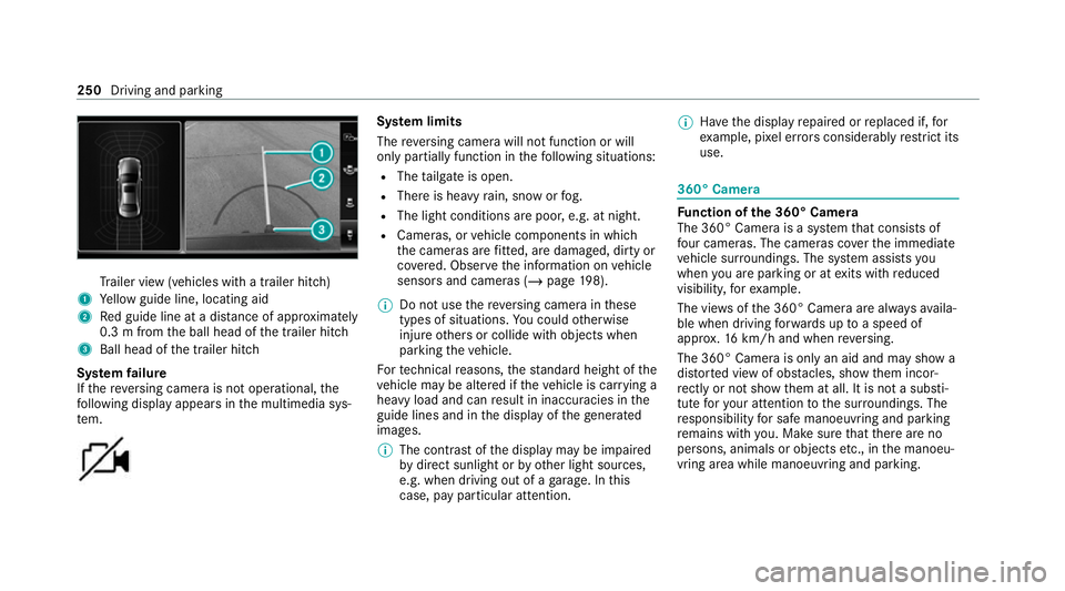
ailer view (vehicles with a trailer hit ch)
1 Yellow guide line, locating aid
2 Red guide line at a dis tance of appr oximately
0.3 m from the ball head of the trailer hitch
3 Ball head of the trailer hitch
Sy stem failure
If th ere ve rsing camera is not operational, the
fo llowing display appears in the multimedia sys‐
te m. Sy
stem limits
The reve rsing camera will not function or will
only partially function in thefo llowing situations:
R The tailgate is open.
R There is heavy rain, snow or fog.
R The light conditions are poor, e.g. at night.
R Cameras, or vehicle components in which
th e cameras are fitted, are dama ged, dirty or
co vered. Obser vethe information on vehicle
sensors and cameras (/ page198).
% Do not use there ve rsing camera in these
types of situations. You could otherwise
injure others or collide with objects when
parking theve hicle.
Fo rte ch nical reasons, thest andard height of the
ve hicle may be altered if theve hicle is car rying a
heavy load and can result in inaccuracies in the
guide lines and in the display of thege nerated
ima ges.
% The contra stof the display may be impaired
by direct sunlight or by other light sources,
e.g. when driving out of a garage . In this
case, pay particular attention. %
Have the display repaired or replaced if, for
ex ample, pixel er rors considerably restrict its
use. 360° Came
ra Fu
nction of the 360° Camera
The 360° Camera is a sy stem that consists of
fo ur cameras. The cameras co verth e immediate
ve hicle sur roundings. The sy stem assists you
when you are parking or at exits with reduced
visibility, forex ample.
The vie wsofthe 360° Camera are alw aysav aila‐
ble when driving forw ards up toa speed of
appr ox.16 km/h and when reve rsing.
The 360° Camera is only an aid and may show a
dis torted view of obs tacles, show them incor‐
re ctly or not show them at all. It is not a substi‐
tute foryo ur attention tothe sur roundings. The
re sponsibility for safe manoeuvring and parking
re mains with you. Make sure that there are no
persons, animals or objects etc., in the manoeu‐
vring area while manoeuvring and parking. 250
Driving and parking
Page 256 of 525
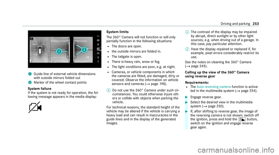
1
Guide line of extern al vehicle dimensions
with outside mir rors folded out
2 Marker of the wheel conta ct points
Sy stem failure
If th e sy stem is not ready for operation, thefo l‐
lowing message appears in the media display: Sy
stem limits
The 360° Camera will not function or will only
partially function in thefo llowing situations:
R The doors are open.
R the outside mir rors are folded in.
R The tailgate is open.
R There is heavy rain, snow or fog.
R The light conditions are poor, e.g. at night.
R Cameras, or vehicle components in which
th e cameras are fitted, are dama ged, dirty or
co vered. Obser vethe information on vehicle
sensors and cameras (/ page198).
% Do not use the 360° Camera under such cir‐
cums tances. You could otherwise injure oth‐
ers or collide with objects when parking the
ve hicle.
Fo rte ch nical reasons, thest andard height of the
ve hicle may be altered if theve hicle is car rying a
heavy load and can result in inaccuracies in the
guide lines and in the display of thege nerated
ima ges. %
The contra stof the display may be impaired
by abrupt, direct sunlight or by other light
sources, e.g. when driving out of a garage . In
th is case, pay particular attention.
% Have the display repaired or replaced if, for
ex ample, pixel er rors considerably restrict its
use.
See the no tes on cleaning the 360° Camera
(/ page 345).
Calling up the view of the 360° Camera
using reve rsege ar
Re quirements:
R The Auto reversing camera function is activa‐
te d in the multimedia sy stem (/ page 254). #
Enga gereve rsege ar. #
Select the desired view in the multimedia
sy stem (/ page 250). #
If, af ter shifting toreve rsege ar, the image of
th ere ve rsing camera is not shown: switch off
th e ignition, press and hold thec button,
switch on the ignition and engage reve rse
ge ar again. Driving and parking
253
Page 349 of 525
%
Afterch anging the wiper blades or treating
th eve hicle with wax, clean the windscreen
th oroughly with cleaning agents recommen‐
ded for Mercedes-Benz. Failure toobser ve
th e application instructions may result in
damage, smear mar ksor dazzling spots.
% Remo veextern al fogging or dirt on the wind‐
screen in front of the multifunction camera.
Otherwise, driving sy stems and driving
saf ety sy stems may be impaired or not avail‐
able (/ page198).
Wi per blades
R Movethe wiper arms into there placement
position (/ page143).
R With th e wiper arms folded out, clean the
wiper blades with a damp clo th.
% Make sure that the wiper blades are coated.
The coating can lea veresidues on a clo th.
Do not rubth e wiper blades excessively or
clean them too of ten.
Ex terior lighting
R Clean the lenses with a wet sponge and mild
cleaning agent, e.g. car sha mpoo. R
Only use cleaning agents or cleaning clo ths
th at are suitable for plast ic lenses.
Sensors
R Clean the sensors in the front and rear
bumpers with a soft clo thand car shampoo
(/ page 198).
R When using a high -pressure cleaner,maintain
a minimum dis tance of 30 cm.
Ru nning boards
R Use wate r and acid-free cleaning agents.
R Do not clean the aluminium trim insert of the
ru nning board wi thalkaline or acidic cleaning
agents such as wheel cleaners. Do not use
acidic alloy wheel cleaners toremo vebrake
dust. The aluminium trim inserts could other‐
wise be damaged.
Re versing camera and 360° Camera
R Open the camera co ver with the multimedia
sy stem (/ page 254).
R Use clean water and a soft clo thtoclean the
came ralens.
R Do not use a high-pressure cleaner. Ta
ilpipes
R Clean with a cleaning agent recommended
fo r Mercedes-Benz, especially in the winter
and af terwa shing theve hicle.
R Do not use acidic cleaning agents.
Tr ailer hitch
R Obse rveth e no tes on care in the trailer hitch
manufacturer's operating instructions.
R Do not clean the ball neck with a high-pres‐
sure cleaner or solvent.
R Remo vetraces of rust on the ball, forex am‐
ple, with a wire brush.
R Remo vedirt with a lint-free clo th.
R After cleaning, lightly oil or grease the ball
head.
% Before using trailers with anti- torsional cou‐
pling, obser vethe manufacturer's operating
instructions. 346
Maintenance and care
Page 470 of 525
Wa
rning and indicator lamps Overview of indicator and
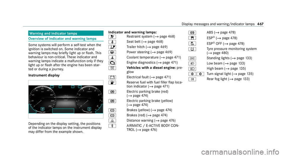
warning lamps Some sy
stems will per form a self-test when the
ignition is switched on. Some indicator and
wa rning lamps may briefly light up or flash. This
behaviour is non-critical. These indicator and
wa rning lamps indicate a malfunction only if they
light up or flash af terth e engine has been star‐
te d or during a journe y.
Instrument display Depending on
the display setting, the positions
of the indicator lamps on the instrument display
may dif fer from theex ample shown. Indicator and
warning lamps:
0075 Re
stra int sy stem (/ page 468)
00E9 Seat belt (/
page 468)
ï Trailer hit ch (/page 469)
Ù Powe rst eering (/ page 469)
ÿ Coolanttemp erature (/ page471)
00B9 Engine diagnostics (/
page471)
0028 Ve
hicles with a diesel engine: pre‐
gl ow
003D Electrical
fault (/ page471)
00B6 Re
ser vefuel with fuel filler flap loca‐
tion indicator (/ page471)
0024 Electric parking brake (red)
(/
page 474)
0024 Electric parking brake (yell
ow)
( / page 474)
004D Brakes (yell
ow) (/ page 474)
004D Brakes (red) (/
page 474)
L Distance warning (/ page476)
ä AIRMATIC / E- ACTIVE BODY CON‐
TROL (/ page476) 0025
ABS (/
page478)
00E5 ESP®
(/ page 478)
00BB ESP®
OFF (/ page478)
0077 Ty
re pressure monitoring sy stem
(/ page 480)
0060 St
anding lights (/ page133)
0058 Low beam (/
page133)
0057 High beam (/
page135)
003E003D Tu
rn signal light (/ page135)
005E Re
ar fog light (/ page133) Displ
aymessa ges and warning/indicator lamps 467
Page 503 of 525
Light adjust
ment
Low beam (d riving abroad). ................... 13 3
Light switch Overview............................................... 13 3
Lighting see In terior lighting
see Lights
Lights Active headla mps.................................. 13 6
Ad aptive Highbeam Assist Plus............ .138
Au tomatic driving lights........................ .134
Combination switch.............................. .135
Cornering light....................................... 13 6
Driving ab road (low beam light
adjustment).......................................... .133
Fo g light (enhanced)..............................1 37
Haza rdwa rning light s............................ 13 5
Headla mpflashin g................................. 13 5
High beam............................................. 13 5
Intellige nt Light Sy stem......................... 13 6
Light switc h........................................... 13 3
Low beam..............................................1 33
Mo torw ay mode..................................... 137
Off-road light.........................................1 38
Pa rking lights........................................ .133 Re
ar fog light......................................... 13 3
Re sponsibility for lighting sy stems........ 13 3
Setting low beam................................... 14 0
Setting theex terior lighting switch-
off delay time........................................1 40
St anding lights....................................... 13 3
Switching the Intelligent Light Sys‐
te m on/of f............................................ 13 8
Switching the sur round lighting on/
off......................................................... .140
Tu rn signal indicator.............................. 13 5
Limiter Activating.............................................. 209
Buttons.................................................. 209
Calling up a spee d................................. 209
Deactivating.......................................... 209
Fu nction................................................ 208
Pa ssive mode........................................ 208
Pe rm anent setting.................................. 211
Re quirements........................................ 209
Selecting.............................................. .209
Setting a speed..................................... 209
St oring a speed............................. 209, 214
Switching off/deacti vating.................... 214
Switching on/activating........................ 214Sy
stem limits.........................................2 08
Limiting speed see Limiter
Limiting the opening angle (tailgate) ........87
LINGU ATRO NIC
Fu nction................................................ 287
St arting................................................. 287
Live Traf fic Information
Swit ching the tra ffic information dis‐
play on.................................................. 302
Load compa rtment floor
Locking/unlockin g................................ 12 5
Load pr otection net
At tach ing.............................................. .121
Loading Bag hook.............................................. .123
Coat hook.............................................. 124
No tes..................................................... 11 4
Ro of luggage rack .................................. 12 6
Ti e-down eyes........................................ 12 2
Loading see EA SY-PAC K load-securing kit
Loading guidelines..................................... 11 4500
Index
Page 509 of 525
see PRE-SAFE
®
PLUS (anticipatory
occupant pr otection plus)
Profile Creating a new profile........................... 292
Notes.................................................... 290
Selecting profile options....................... 292
Prog rams
see DYNA MIC SELECT
Pr otection of the environment
No tes....................................................... 22
Ta ke -ba ckof end-of-life vehicles..............22 Q
QR code Rescue card............................................35
Qualified specialist workshop ...................33 R
Ra dar and ultrasonic senso rs
Damage................................................. 19 8
Ra dio
Overview of the functions and sym‐
bols....................................................... 329 Ra
in-closing feature
Side wind ows.......................................... 89
Sliding sunroof........................................ 94
Ra ising theve hicle
Re ar of theve hicle................................. 241
REACH regulation........................................34
Re ading lamp
see Interior lighting
Re ading light
Switching on/off with hand mo ve‐
ments.................................................... 290
Re alwo od (Care) ...................................... .347
Re ar climate control
Setting (MBUX multimedia sy stem).......1 52
Re ar door (child saf ety lock)...................... 72
Re ar fog light
Switching on/off................................... 13 4
Re ar of theve hicle
Lo we ring................................................ 241
Ra ising.................................................. .241
Re ar seat
see Seat Re
ar seat belt
St atus display......................................... .44
Re ar seat belt status display ..................... 44
Re ar window heater.................................. 15 0
Re ar-view mir ror
Anti-dazzle mode (automatic)................ 147
Re ar-view mir ror
see Outside mir rors
Re cycling
see Take -ba ckof end-of-life vehicles
Re ducing agent
see AdBlue ®
Re fuelling
Re fuelling theve hicle............................1 85
Re gistration
Ve hicle.................................................... 33
Re gulatory radio identification................ 391
Re mo tecont rol (stationa ryheater/
ve ntilation)
Displa ys................................................. 15 8
Problems............................................... 15 9
Re placing the battery............................ 15 8506
Index