battery location MERCEDES-BENZ GLE SUV 2015 Owners Manual
[x] Cancel search | Manufacturer: MERCEDES-BENZ, Model Year: 2015, Model line: GLE SUV, Model: MERCEDES-BENZ GLE SUV 2015Pages: 453, PDF Size: 14.78 MB
Page 14 of 453
ETS/4ETS (Electronic Traction Sys-
tem) ...................................................... 76
Exhaust pipe (cleaning instruc-
tions) .................................................. 383
Exhaustive discharging (high-volt-
age battery) ...................................... .394
Exterior mirrors
Adjusting ....................................... 117
Anti-dazzle mode (automatic) ....... .118
Folding in when locking (on-board
computer) ...................................... 296
Folding in/out (automatically) ....... 118
Folding in/out (electrically) ........... 118
Out of position (troubleshooting) ... 118
Parking position ............................. 119
Resetting ....................................... 118
Storing settings (memory func-
tion) ............................................... 120 F
Fault message see Display messages
Filler cap
see Fuel filler flap
Fire extinguisher ............................... 387
First-aid kit ......................................... 386
Fitting a wheel
Fitting a wheel ............................... 416
Lowering the vehicle ...................... 417
Preparing the vehicle ..................... 414
Raising the vehicle ......................... 415
Removing a whee l.......................... 416
Securing the vehicle against roll-
ing away ........................................ 414
Flat tyre
MOExtended tyre s......................... 388
Preparing the vehicle ..................... 388
TIREFIT kit ...................................... 389
see Emergency spare wheel
Floormat ............................................. 372
Foglamps (extended range) .............. 125
Folding the rear bench seat for-
wards/back ....................................... 354
Fording
Off-road ......................................... 198
On flooded roads ........................... 197 Frequencies
Garage door opener ....................... 369
Mobile phone ................................. 433
Two-way radio ................................ 433
Front-passenger front airbag deac-
tivation
Display message ............................ 311
Front-passenger front airbag deac-
tivation system
Operation ......................................... 51
Problems ......................................... 55
System self-test ............................... 54
Fuel
Additives ........................................ 437
Consumption information .............. 438
Consumption statistics .................. 284
Displaying the current consump-
tion ................................................ 285
Displaying the range ...................... 285
Driving tips .................................... 194
Fuel gaug e....................................... 32
Grade (petrol) ................................ 436
Important safety notes .................. 436
Low outside temperatures ............. 438
Notes for Mercedes‑ AMG vehi-
cles ................................................ 437
Problem (malfunction) ................... 179
Quality (diesel )............................... 438
Refuelling ....................................... 175
Tank content/reserve fue l............. 436
Fuel filler flap
Opening ......................................... 177
Opening (PLUG-IN HYBRID vehi-
cles) ............................................... 177
Fuel filter (white display message) .. 318
Fuel level
Calling up the range (on-board
computer) ...................................... 285
Gaug e.............................................. 32
Fuel tank
Capacity ........................................ 436
Problem (malfunction) ................... 179
Fuses
Allocation chart ............................. 402
Before changing ............................. 402
Dashboard fuse box ....................... 402
Fuse box in the engine compart-
ment .............................................. 403 Index
11
Page 16 of 453
Instrument cluster lighting
.............. 281
Intelligent Light System
Activating/deactivating ................ .294
Display message ............................ 314
Overview ........................................ 124
Setting the dipped-beam head-
lamps for driving on the right/left .. 294
Interior lighting
Automatic control system .............. 127
Emergency lighting ........................ 128
Manual control ............................... 127
Overview ........................................ 127
Reading lamp ................................. 127
Interior motion sensor
Deactivating ..................................... 83
Function .......................................... .82
Priming ............................................ 82
Switching off .................................... 82
ISOFIX child seat securing system ....60J
Jack Storage location ............................3 87
Using ............................................. 415
Jump starting (engine) ......................397 K
Key Changing the battery ....................... 87
Checking the battery ....................... 87
Convenience closing feature .......... 100
Convenience opening feature .......... 99
Display message ............................ 336
Door central locking/unlocking ....... 85
Emergency key element ................... 86
Important safety notes .................... 84
KEYLESS-GO start function .............. 86
Loss ................................................. 89
Modifying the programming ............. 86
Overview .......................................... 84
Positions (ignition lock) ................. 158
Problem (malfunction) ..................... 89
Starting the engine ........................ 160
Key positions
Key ................................................ 158
KEYLESS GO .................................. 158 KEYLESS-GO
Convenience closing ..................... .100
Deactivation ..................................... 85
Display message ............................ 336
Locking ............................................ 85
Removing the Start/Stop button ... 159
Start function ................................... 86
Start/Stop button .......................... 158
Starting the engine ........................ 160
Unlocking ......................................... 85
Kickdown
Driving tips ................................... .170
Manual gearshifting ....................... 174
Kneebag ............................................... 50 L
Lamps see Warning and indicator lamps
Lane detection (automatic)
see Lane Keeping Assist
Lane Keeping Assist
Activating/deactivating ................. 291
Display message ............................ 325
Function/informatio n.................... 246
see Active Lane Keeping Assist
Lap time (RACETIMER) ...................... 298
Lashing eyelets ................................. 355
Level control (display message) ...... 322
Level control (vehicle with the Off- Road Engineering package)
Basic settings ................................ 217
Function/note s............................. 216
Important safety notes .................. 216
Licence plate lamp (display mes-
sage) ................................................... 314
Light sensor (display message) ....... 315
Lighting
see Lights
Lights
Activating/deactivating the Intel-
ligent Light System ........................ 294
Active light function ....................... 124
Adaptive Highbeam Assist PLUS .... 126
Automatic headlamp mode ............ 122
Cornering light function ................. 124
Dipped-beam headlamp s............... 122
Driving abroad ............................... 121 Index
13
Page 155 of 453
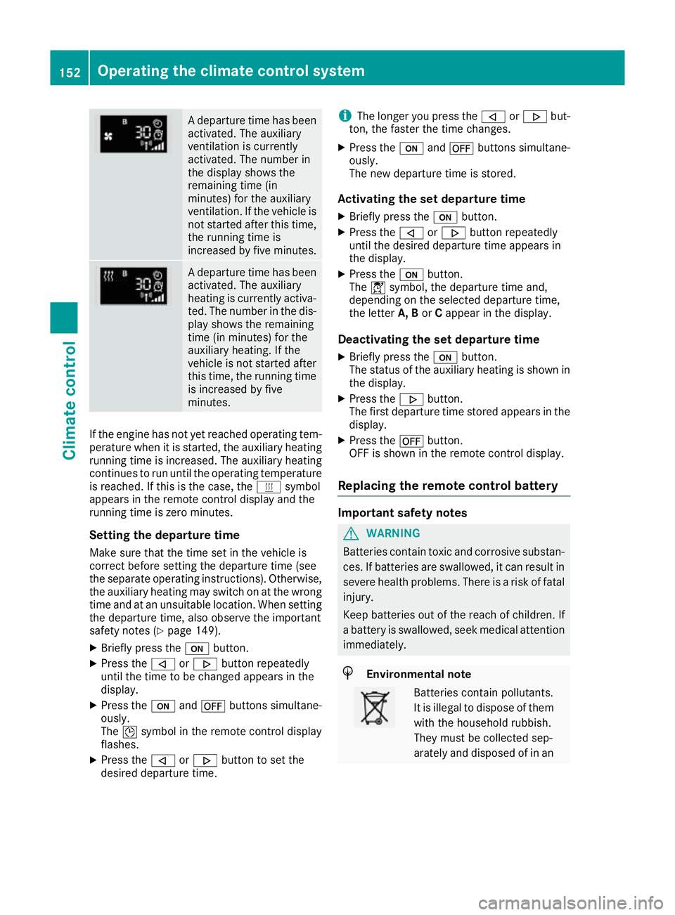
A departure time has been
activated. The auxiliary
ventilation is currently
activated. The number in
the display shows the
remaining time (in
minutes) for the auxiliary
ventilation. If the vehicle is
not started after this time, the running time is
increased by five minutes. A departure time has been
activated. The auxiliary
heating is currently activa-
ted. The number in the dis- play shows the remaining
time (in minutes) for the
auxiliary heating. If the
vehicle is not started after
this time, the running time is increased by five
minutes. If the engine has not yet reached operating tem-
perature when it is started, the auxiliary heating running time is increased. The auxiliary heating
continues to run until the operating temperature
is reached. If this is the case, the ysymbol
appears in the remote control display and the
running time is zero minutes.
Setting the departure time
Make sure that the time set in the vehicle is
correct before setting the departure time (see
the separate operating instructions). Otherwise, the auxiliary heating may switch on at the wrong
time and at an unsuitable location. When setting the departure time, also observe the important
safety notes (Y page 149).
X Briefly press the ubutton.
X Press the ,or. button repeatedly
until the time to be changed appears in the
display.
X Press the uand^ buttons simultane-
ously.
The Îsymbol in the remote control display
flashes.
X Press the ,or. button to set the
desired departure time. i
The longer you press the
,or. but-
ton, the faster the time changes.
X Press the uand^ buttons simultane-
ously.
The new departure time is stored.
Activating the set departure time
X Briefly press the ubutton.
X Press the ,or. button repeatedly
until the desired departure time appears in
the display.
X Press the ubutton.
The Ísymbol, the departure time and,
depending on the selected departure time,
the letter A, BorCappear in the display.
Deactivating the set departure time
X Briefly press the ubutton.
The status of the auxiliary heating is shown in the display.
X Press the .button.
The first departure time stored appears in the
display.
X Press the ^button.
OFF is shown in the remote control display.
Replacing the remote control battery Important safety notes
G
WARNING
Batteries contain toxic and corrosive substan- ces. If batteries are swallowed, it can result in
severe health problems. There is a risk of fatal injury.
Keep batteries out of the reach of children. If
a battery is swallowed, seek medical attention immediately. H
Environmental note Batteries contain pollutants.
It is illegal to dispose of them
with the household rubbish.
They must be collected sep-
arately and disposed of in an 152
Operating the climate control systemClimate control
Page 189 of 453
When displays
:and ;on the charging cable
light up, this means the following: Display
:
: Lights up
green The on-board voltage is con-
nected. The high-voltage bat-
tery can be charged.
Flashes red The power supply from the
building is faulty.
Display
; ; Lights up
green There are no faults. The high-
voltage battery can be
charged.
Lights up red The protective and indicator
system has detected a fault
due to an internal malfunc-
tion. The high-voltage battery
cannot be charged. If the control detects residual current or a mal-
function, the charging process is halted. Once
the malfunction has been rectified the charging process is resumed automatically.
Information on problems relating to the charg-
ing process (Y page 190).
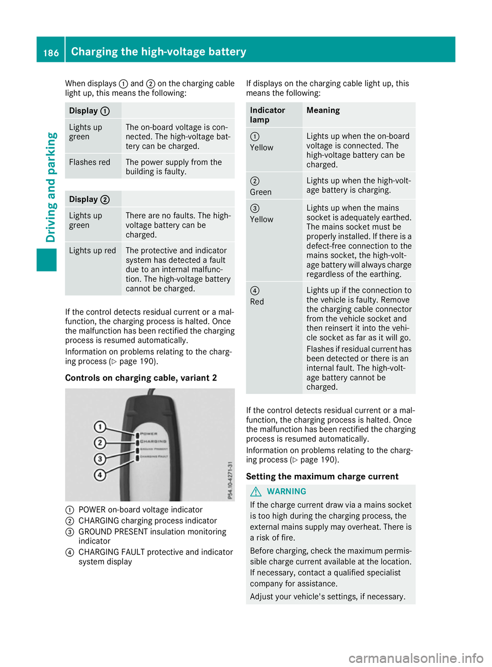
Controls on charging cable, variant 2 :
POWER on-board voltage indicator
; CHARGING charging process indicator
= GROUND PRESENT insulation monitoring
indicator
? CHARGING FAULT protective and indicator
system display If displays on the charging cable light up, this
means the following: Indicator
lamp Meaning
:
Yellow
Lights up when the on-board
voltage is connected. The
high-voltage battery can be
charged.
;
Green
Lights up when the high-volt-
age battery is charging.
=
Yellow
Lights up when the mains
socket is adequately earthed.
The mains socket must be
properly installed. If there is a defect-free connection to the
mains socket, the high-volt-
age battery will always charge
regardless of the earthing. ?
Red
Lights up if the connection to
the vehicle is faulty. Remove
the charging cable connector
from the vehicle socket and
then reinsert it into the vehi-
cle socket as far as it will go.
Flashes if residual current has been detected or there is an
internal fault. The high-volt-
age battery cannot be
charged. If the control detects residual current or a mal-
function, the charging process is halted. Once
the malfunction has been rectified the charging process is resumed automatically.
Information on problems relating to the charg-
ing process (Y page 190).
Setting the maximum charge current G
WARNING
If the charge current draw via a mains socket is too high during the charging process, the
external mains supply may overheat. There isa risk of fire.
Before charging, check the maximum permis-
sible charge current available at the location.
If necessary, contact a qualified specialist
company for assistance.
Adjust your vehicle's settings, if necessary. 186
Charging the high-voltage batteryDriving and parking
Page 339 of 453
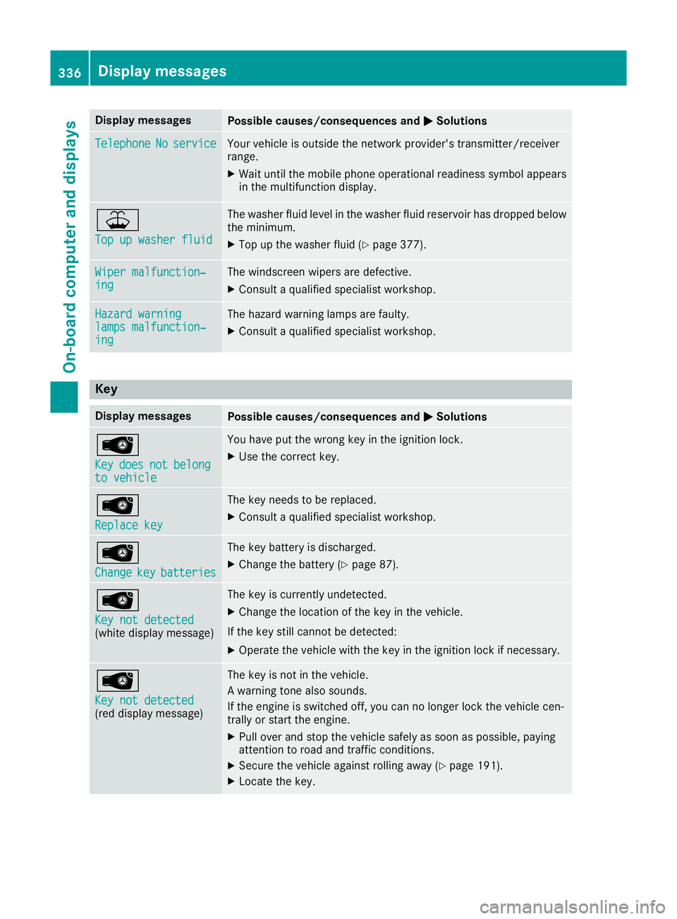
Display messages
Possible causes/consequences and
M
MSolutions Telephone
Telephone
No
Noservice
service Your vehicle is outside the network provider's transmitter/receiver
range.
X Wait until the mobile phone operational readiness symbol appears
in the multifunction display. ¥
Top up washer fluid Top up washer fluid The washer fluid level in the washer fluid reservoir has dropped below
the minimum.
X Top up the washer fluid (Y page 377).Wiper malfunction‐
Wiper malfunction‐
ing ing The windscreen wipers are defective.
X Consult a qualified specialist workshop. Hazard warning
Hazard warning
lamps malfunction‐ lamps malfunction‐
ing ing The hazard warning lamps are faulty.
X Consult a qualified specialist workshop. Key
Display messages
Possible causes/consequences and
M
MSolutions Â
Key Key
does
does not
notbelong
belong
to vehicle
to vehicle You have put the wrong key in the ignition lock.
X Use the correct key. Â
Replace key Replace key The key needs to be replaced.
X Consult a qualified specialist workshop. Â
Change Change
key
keybatteries
batteries The key battery is discharged.
X Change the battery (Y page 87).Â
Key not detected Key not detected
(white display message) The key is currently undetected.
X Change the location of the key in the vehicle.
If the key still cannot be detected:
X Operate the vehicle with the key in the ignition lock if necessary. Â
Key not detected Key not detected
(red display message) The key is not in the vehicle.
A warning tone also sounds.
If the engine is switched off, you can no longer lock the vehicle cen-
trally or start the engine.
X Pull over and stop the vehicle safely as soon as possible, paying
attention to road and traffic conditions.
X Secure the vehicle against rolling away (Y page 191).
X Locate the key. 336
Display
messagesOn-board computer and displays
Page 403 of 453
tance a distance so that the tow rope does
not sag.
R Do not use steel cables or chains to tow
your vehicle. You could otherwise damage
the vehicle.
! Do not use the trailer tow hitch for recovery
or towing. Do not use the towing eye for
recovery. This could damage the vehicle. If in doubt, have the vehicle recovered using a
crane.
! When towing, pull away slowly and
smoothly. Pull the towed vehicle as straight as possible and not at an acute angle. If the trac-
tive power is too high, the vehicles could be
damaged.
When towing, it is preferable to use a rigid tow- ing bar as opposed to a tow rope. A rigid towing
bar helps to keep the tractive power low.
! To tow vehicles with KEYLESS-GO, use the
key instead of the Start/Stop button. The
automatic transmission may otherwise
switch to position Pwhen you open the driv-
er's or front-passenger door which could
damage the transmission.
! Vehicles with differential locks: make sure
the differential locks are in automatic mode.
When towing, the differential locks must not
be switched on. The transmission may other- wise be damaged.
! You may tow the vehicle for a maximum of
50km. A towing speed of 50 km/h must not
be exceeded.
For towing distances over 50 km, the entire
vehicle must be lifted up and transported.
Observe the legal requirements for the relevant countries when towing.
It is better to have the vehicle transported than
to have it towed.
If the vehicle has suffered transmission damage, have it transported on a transporter or trailer.
The automatic transmission must be in position
N when the vehicle is being towed away.
The battery must be connected and charged.
Otherwise, you:
R cannot turn the key to position 2in the igni-
tion lock
R cannot release the electric parking brake
R cannot shift the automatic transmission to
position N Deactivate the automatic locking feature before
towing the vehicle (Y page 294). You could oth-
erwise be locked out when pushing or towing
the vehicle.
Deactivate tow-away protection before the vehi-
cle is towed away (Y page 82).
PLUG-IN HYBRID vehicles:
PLUG-IN HYBRID vehicles may not be towed
away but must instead be transported, if:
R the multifunction display is not working or
R the á Towing
Towing not notpermitted
permitted See
SeeOwn‐
Own‐
er's Manual
er's Manual message appears in the multi-
function display.
If the vehicle is in a dangerous location it may be
towed from the danger zone with both axles on
the ground. In this case, the towing distance
may not be greater than 50 m andthe towing
speed must not exceed 10 km/h. For longer
distances, have the vehicle loaded and trans-
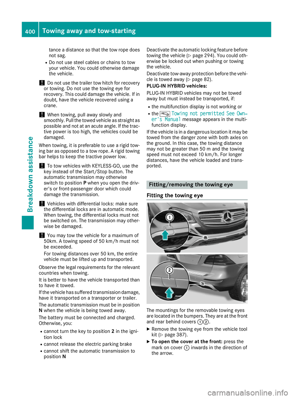
ported. Fitting/removing the towing eye
Fitting the towing eye The mountings for the removable towing eyes
are located in the bumpers. They are at the front and rear behind covers :;.
X Remove the towing eye from the vehicle tool
kit (Y page 387).
X To open the cover at the front: press the
mark on cover :inwards in the direction of
the arrow. 400
Towing away and tow-startingBreakdown assistance
Page 405 of 453
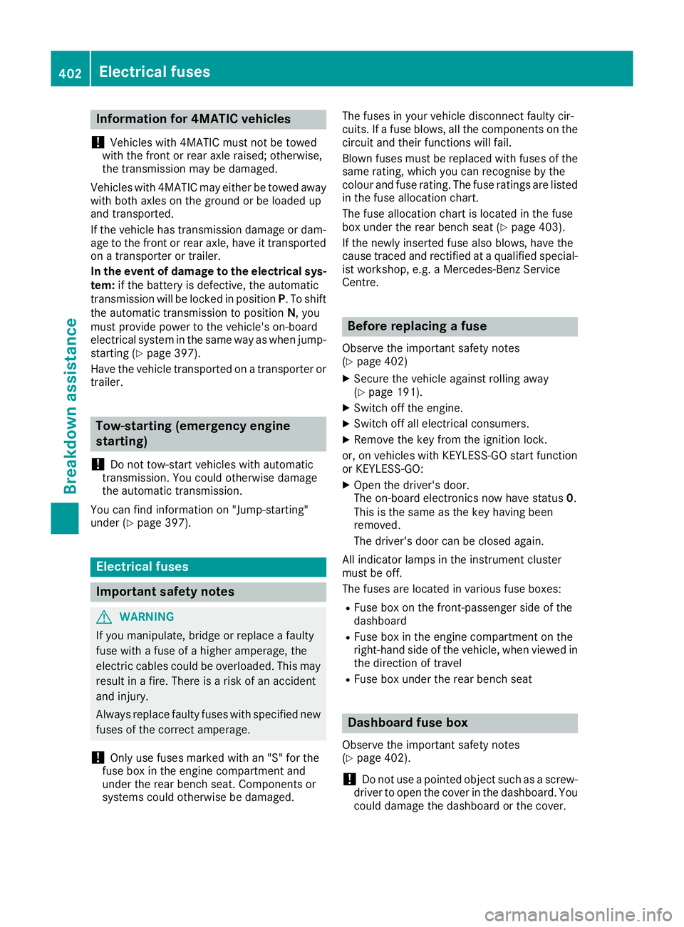
Information for 4MATIC vehicles
! Vehicles with 4MATIC must not be towed
with the front or rear axle raised; otherwise,
the transmission may be damaged.
Vehicles with 4MATIC may either be towed away
with both axles on the ground or be loaded up
and transported.
If the vehicle has transmission damage or dam- age to the front or rear axle, have it transportedon a transporter or trailer.
In the event of damage to the electrical sys-
tem: if the battery is defective, the automatic
transmission will be locked in position P. To shift
the automatic transmission to position N, you
must provide power to the vehicle's on-board
electrical system in the same way as when jump- starting (Y page 397).
Have the vehicle transported on a transporter or trailer. Tow-starting (emergency engine
starting)
! Do not tow-start vehicles with automatic
transmission. You could otherwise damage
the automatic transmission.
You can find information on "Jump-starting"
under (Y page 397). Electrical fuses
Important safety notes
G
WARNING
If you manipulate, bridge or replace a faulty
fuse with a fuse of a higher amperage, the
electric cables could be overloaded. This may result in a fire. There is a risk of an accident
and injury.
Always replace faulty fuses with specified new fuses of the correct amperage.
! Only use fuses marked with an "S" for the
fuse box in the engine compartment and
under the rear bench seat. Components or
systems could otherwise be damaged. The fuses in your vehicle disconnect faulty cir-
cuits. If a fuse blows, all the components on the
circuit and their functions will fail.
Blown fuses must be replaced with fuses of the same rating, which you can recognise by the
colour and fuse rating. The fuse ratings are listed
in the fuse allocation chart.
The fuse allocation chart is located in the fuse
box under the rear bench seat (Y page 403).
If the newly inserted fuse also blows, have the
cause traced and rectified at a qualified special-
ist workshop, e.g. a Mercedes-Benz Service
Centre. Before replacing a fuse
Observe the important safety notes
(Y page 402)
X Secure the vehicle against rolling away
(Y page 191).
X Switch off the engine.
X Switch off all electrical consumers.
X Remove the key from the ignition lock.
or, on vehicles with KEYLESS-GO start function
or KEYLESS‑GO: X Open the driver's door.
The on-board electronics now have status 0.
This is the same as the key having been
removed.
The driver's door can be closed again.
All indicator lamps in the instrument cluster
must be off.
The fuses are located in various fuse boxes: R Fuse box on the front-passenger side of the
dashboard
R Fuse box in the engine compartment on the
right-hand side of the vehicle, when viewed in
the direction of travel
R Fuse box under the rear bench seat Dashboard fuse box
Observe the important safety notes
(Y page 402).
! Do not use a pointed object such as a screw-
driver to open the cover in the dashboard. You
could damage the dashboard or the cover. 402
Electrical fusesBreakdown assistance