oil pressure MERCEDES-BENZ GLE SUV 2019 Owner's Manual
[x] Cancel search | Manufacturer: MERCEDES-BENZ, Model Year: 2019, Model line: GLE SUV, Model: MERCEDES-BENZ GLE SUV 2019Pages: 398, PDF Size: 12.25 MB
Page 23 of 398
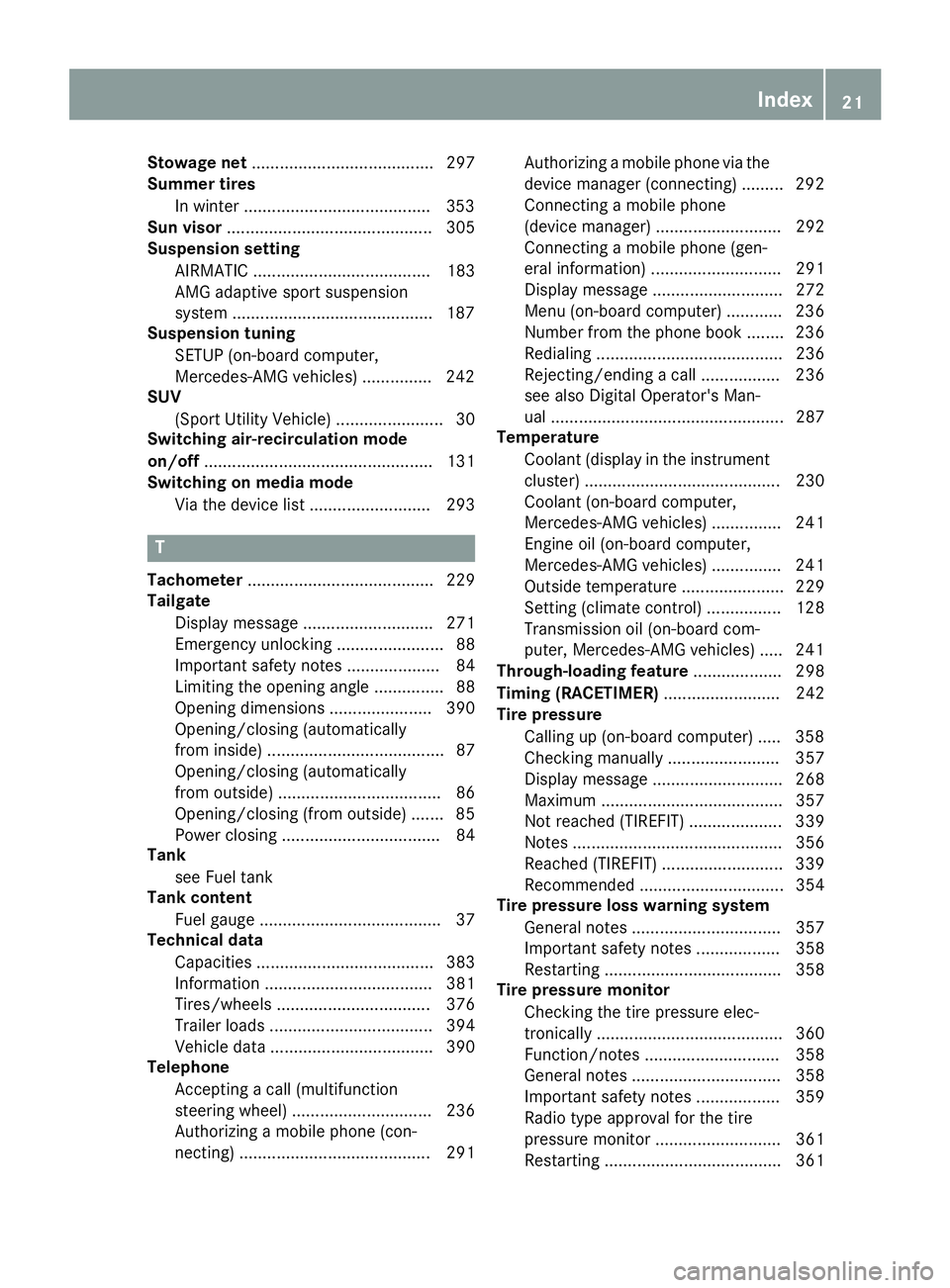
Stowage net
....................................... 297
Summer tires
In winter ........................................3 53
Sun visor ............................................ 305
Suspension setting
AIRMATIC ...................................... 183
AMG adaptive sport suspension
system .......................................... .187
Suspension tuning
SETUP (on-board computer,
Mercedes-AMG vehicles) .............. .242
SUV
(Sport Utility Vehicle) ....................... 30
Switching air-recirculation mode
on/off ................................................. 131
Switching on media mode
Via the device lis t.......................... 293 T
Tachometer ........................................ 229
Tailgate
Display message ............................ 271
Emergency unlocking ....................... 88
Important safety notes .................... 84
Limiting the opening angle ............... 88
Opening dimensions ...................... 390
Opening/closing (automatically
from inside) ...................................... 87
Opening/closing (automatically
from outside) ................................... 86
Opening/closing (from outside) ....... 85
Power closing .................................. 84
Tank
see Fuel tank
Tank content
Fuel gauge ....................................... 37
Technical data
Capacities ...................................... 383
Information .................................... 381
Tires/wheels ................................. 376
Trailer loads ................................... 394
Vehicle data ................................... 390
Telephone
Accepting a call (multifunction
steering wheel) .............................. 236
Authorizing a mobile phone (con-
necting) ......................................... 291 Authorizing a mobile phone via the
device manager (connecting) ......... 292
Connecting a mobile phone
(device manager) ........................... 292
Connecting a mobile phone (gen-
eral information) ............................ 291
Display message ............................ 272
Menu (on-board computer) ............ 236
Number from the phone book ........ 236
Redialing ........................................ 236
Rejecting/ending a call ................. 236
see also Digital Operator's Man-
ual .................................................. 287
Temperature
Coolant (display in the instrumentcluster) .......................................... 230
Coolant (on-board computer,
Mercedes-AMG vehicles) ............... 241
Engine oil (on-board computer,
Mercedes-AMG vehicles) ............... 241
Outside temperature ...................... 229
Setting (climate control )................ 128
Transmission oil (on-board com-
puter, Mercedes-AMG vehicles) ..... 241
Through-loading feature ................... 298
Timing (RACETIMER) ......................... 242
Tire pressure
Calling up (on-board computer) ..... 358
Checking manually ........................ 357
Display message ............................ 268
Maximum ....................................... 357
Not reached (TIREFIT) .................... 339
Notes ............................................. 356
Reached (TIREFIT) .......................... 339
Recommended ............................... 354
Tire pressure loss warning system
General notes ................................ 357
Important safety notes .................. 358
Restarting ...................................... 358
Tire pressure monitor
Checking the tire pressure elec-
tronically ........................................ 360
Function/note s............................. 358
General notes ................................ 358
Important safety notes .................. 359
Radio type approval for the tire
pressure monitor ........................... 361
Restarting ...................................... 361 Index
21
Page 168 of 398
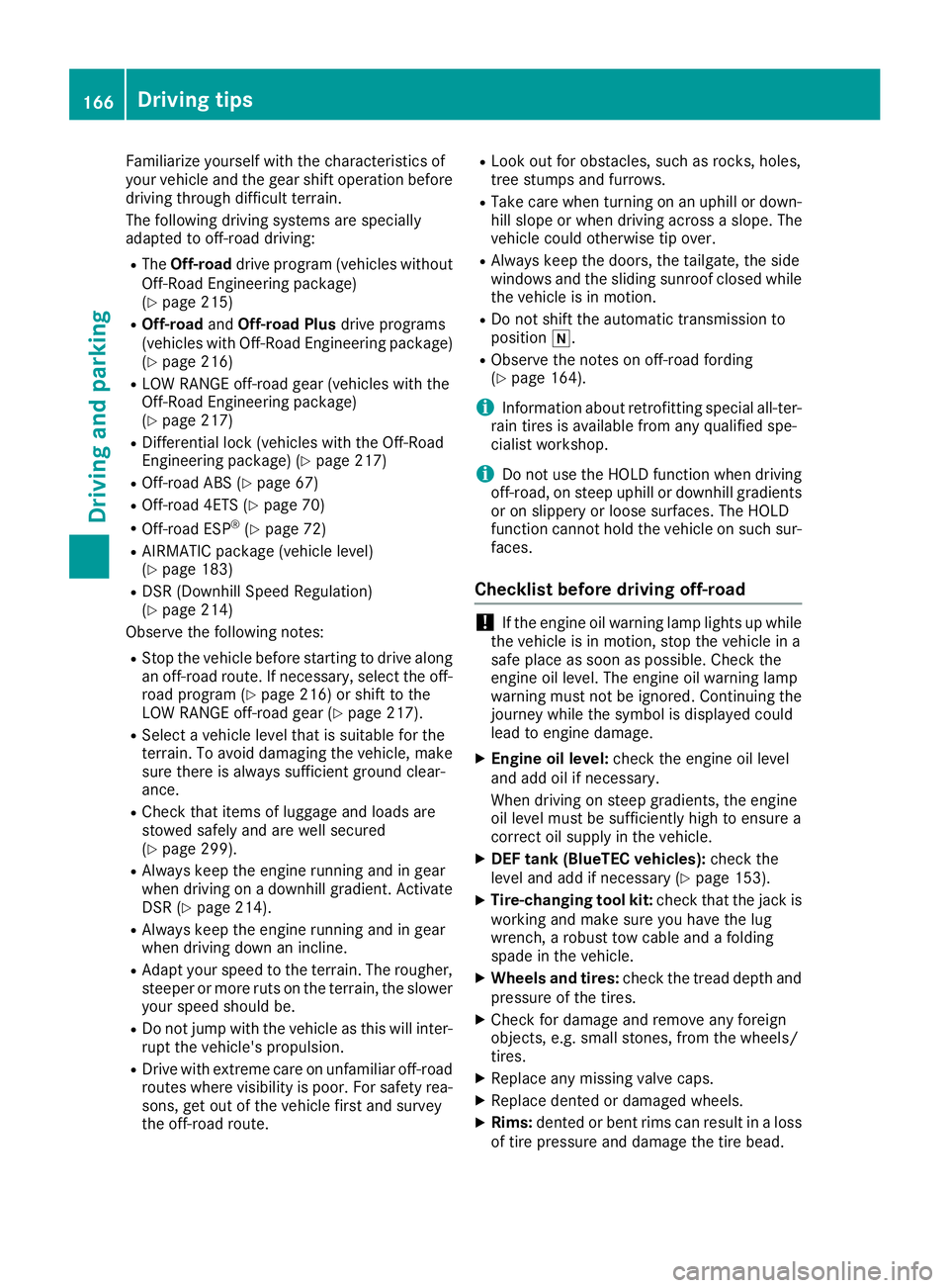
Familiarize yourself with the characteristics of
your vehicle and the gear shift operation before
driving through difficult terrain.
The following driving systems are specially
adapted to off-road driving:
R The Off-road drive program (vehicles without
Off-Road Engineering package)
(Y page 215)
R Off-road andOff-road Plus drive programs
(vehicles with Off-Road Engineering package) (Y page 216)
R LOW RANGE off-road gear (vehicles with the
Off-Road Engineering package)
(Y page 217)
R Differential lock (vehicles with the Off-Road
Engineering package) (Y page 217)
R Off-road ABS (Y page 67)
R Off-road 4ETS (Y page 70)
R Off-road ESP ®
(Y page 72)
R AIRMATIC package (vehicle level)
(Y page 183)
R DSR (Downhill Speed Regulation)
(Y page 214)
Observe the following notes:
R Stop the vehicle before starting to drive along
an off-road route. If necessary, select the off- road program (Y page 216) or shift to the
LOW RANGE off-road gear (Y page 217).
R Select a vehicle level that is suitable for the
terrain. To avoid damaging the vehicle, make
sure there is always sufficient ground clear-
ance.
R Check that items of luggage and loads are
stowed safely and are well secured
(Y page 299).
R Always keep the engine running and in gear
when driving on a downhill gradient. Activate
DSR (Y page 214).
R Always keep the engine running and in gear
when driving down an incline.
R Adapt your speed to the terrain. The rougher,
steeper or more ruts on the terrain, the slower your speed should be.
R Do not jump with the vehicle as this will inter-
rupt the vehicle's propulsion.
R Drive with extreme care on unfamiliar off-road
routes where visibility is poor. For safety rea- sons, get out of the vehicle first and survey
the off-road route. R
Look out for obstacles, such as rocks, holes,
tree stumps and furrows.
R Take care when turning on an uphill or down-
hill slope or when driving across a slope. The
vehicle could otherwise tip over.
R Always keep the doors, the tailgate, the side
windows and the sliding sunroof closed while
the vehicle is in motion.
R Do not shift the automatic transmission to
position 005C.
R Observe the notes on off-road fording
(Y page 164).
i Information about retrofitting special all-ter-
rain tires is available from any qualified spe-
cialist workshop.
i Do not use the HOLD function when driving
off-road, on steep uphill or downhill gradients
or on slippery or loose surfaces. The HOLD
function cannot hold the vehicle on such sur- faces.
Checklist before driving off-road !
If the engine oil warning lamp lights up while
the vehicle is in motion, stop the vehicle in a
safe place as soon as possible. Check the
engine oil level. The engine oil warning lamp
warning must not be ignored. Continuing the
journey while the symbol is displayed could
lead to engine damage.
X Engine oil level: check the engine oil level
and add oil if necessary.
When driving on steep gradients, the engine
oil level must be sufficiently high to ensure a
correct oil supply in the vehicle.
X DEF tank (BlueTEC vehicles): check the
level and add if necessary (Y page 153).
X Tire-changing tool kit: check that the jack is
working and make sure you have the lug
wrench, a robust tow cable and a folding
spade in the vehicle.
X Wheels and tires: check the tread depth and
pressure of the tires.
X Check for damage and remove any foreign
objects, e.g. small stones, from the wheels/
tires.
X Replace any missing valve caps.
X Replace dented or damaged wheels.
X Rims: dented or bent rims can result in a loss
of tire pressure and damage the tire bead. 166
Driving tipsDriving and parking
Page 326 of 398
Further information on engine oil (Y
page 387).Additional service products
Important safety notes G
WARNING
Certain components in the engine compart-
ment, such as the engine, radiator and parts
of the exhaust system, can become very hot.
Working in the engine compartment poses a
risk of injury.
Where possible, let the engine cool down and touch only the components described in the
following. G
WARNING
The cooling system is pressurized, particularly when the motor is warm. If you open the cap, you could be scalded if hot coolant sprays out.
There is a risk of injury.
Let the engine cool down before you open the
cap. Wear protective gloves and protective
eyewear when opening. Open the cap slowly
to release pressure.
The coolant level may only be checked and cool- ant refilled when the engine and engine coolingsystem have cooled down. G
WARNING
Windshield washer concentrate could ignite if it comes into contact with hot engine compo-
nents or the exhaust system. There is a risk of
fire and injury.
Make sure that no windshield washer con-
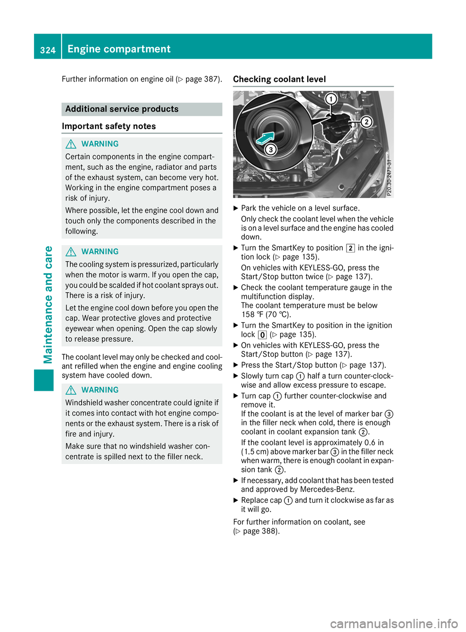
centrate is spilled next to the filler neck. Checking coolant level X
Park the vehicle on a level surface.
Only check the coolant level when the vehicle
is on a level surface and the engine has cooled
down.
X Turn the SmartKey to position 0048in the igni-
tion lock (Y page 135).
On vehicles with KEYLESS-GO, press the
Start/Stop button twice (Y page 137).
X Check the coolant temperature gauge in the
multifunction display.
The coolant temperature must be below
158 ‡ (70 †).
X Turn the SmartKey to position in the ignition
lock 0092(Ypage 135).
X On vehicles with KEYLESS-GO, press the
Start/Stop button (Y page 137).
X Press the Start/Stop button (Y page 137).
X Slowly turn cap 0043half a turn counter-clock-
wise and allow excess pressure to escape.
X Turn cap 0043further counter-clockwise and
remove it.
If the coolant is at the level of marker bar 0087
in the filler neck when cold, there is enough
coolant in coolant expansion tank 0044.
If the coolant level is approximately 0.6 in
(1.5 cm) above marker bar 0087in the filler neck
when warm, there is enough coolant in expan- sion tank 0044.
X If necessary, add coolant that has been tested
and approved by Mercedes-Benz.
X Replace cap 0043and turn it clockwise as far as
it will go.
For further information on coolant, see
(Y page 388). 324
Engine compartmentMaintenance and care
Page 330 of 398
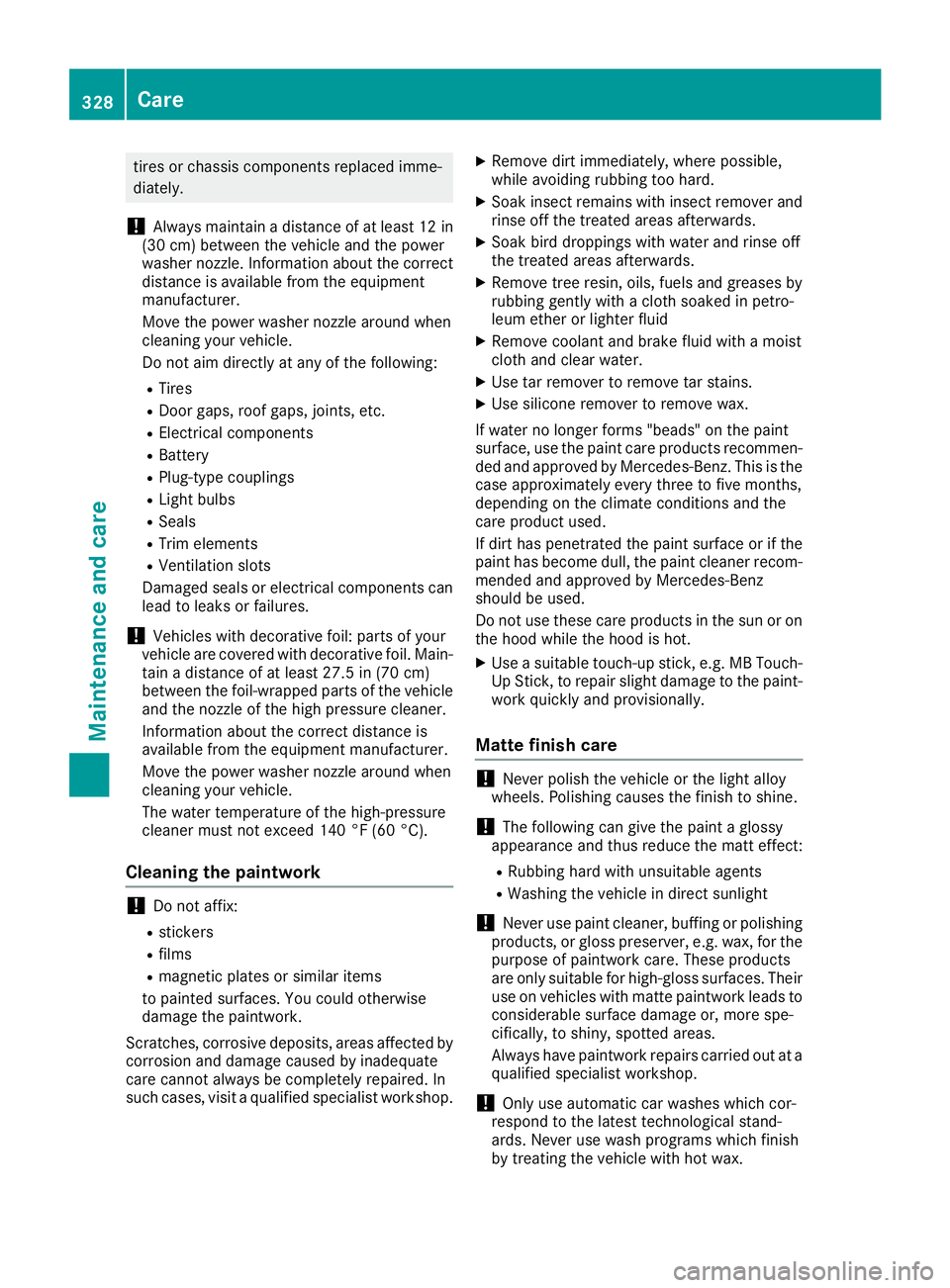
tires or chassis components replaced imme-
diately.
! Always maintain a distance of at least 12 in
(30 cm) between the vehicle and the power
washer nozzle. Information about the correct
distance is available from the equipment
manufacturer.
Move the power washer nozzle around when
cleaning your vehicle.
Do not aim directly at any of the following:
R Tires
R Door gaps, roof gaps, joints, etc.
R Electrical components
R Battery
R Plug-type couplings
R Light bulbs
R Seals
R Trim elements
R Ventilation slots
Damaged seals or electrical components can
lead to leaks or failures.
! Vehicles with decorative foil: parts of your
vehicle are covered with decorative foil. Main- tain a distance of at least 27.5 in (70 cm)
between the foil-wrapped parts of the vehicle and the nozzle of the high pressure cleaner.
Information about the correct distance is
available from the equipment manufacturer.
Move the power washer nozzle around when
cleaning your vehicle.
The water temperature of the high-pressure
cleaner must not exceed 140 °F (60 °C).
Cleaning the paintwork !
Do not affix:
R stickers
R films
R magnetic plates or similar items
to painted surfaces. You could otherwise
damage the paintwork.
Scratches, corrosive deposits, areas affected by
corrosion and damage caused by inadequate
care cannot always be completely repaired. In
such cases, visit a qualified specialist workshop. X
Remove dirt immediately, where possible,
while avoiding rubbing too hard.
X Soak insect remains with insect remover and
rinse off the treated areas afterwards.
X Soak bird droppings with water and rinse off
the treated areas afterwards.
X Remove tree resin, oils, fuels and greases by
rubbing gently with a cloth soaked in petro-
leum ether or lighter fluid
X Remove coolant and brake fluid with a moist
cloth and clear water.
X Use tar remover to remove tar stains.
X Use silicone remover to remove wax.
If water no longer forms "beads" on the paint
surface, use the paint care products recommen-
ded and approved by Mercedes-Benz. This is the
case approximately every three to five months,
depending on the climate conditions and the
care product used.
If dirt has penetrated the paint surface or if the
paint has become dull, the paint cleaner recom-
mended and approved by Mercedes-Benz
should be used.
Do not use these care products in the sun or on the hood while the hood is hot.
X Use a suitable touch-up stick, e.g. MB Touch-
Up Stick, to repair slight damage to the paint-
work quickly and provisionally.
Matte finish care !
Never polish the vehicle or the light alloy
wheels. Polishing causes the finish to shine.
! The following can give the paint a glossy
appearance and thus reduce the matt effect:
R Rubbing hard with unsuitable agents
R Washing the vehicle in direct sunlight
! Never use paint cleaner, buffing or polishing
products, or gloss preserver, e.g. wax, for the purpose of paintwork care. These products
are only suitable for high-gloss surfaces. Their
use on vehicles with matte paintwork leads to
considerable surface damage or, more spe-
cifically, to shiny, spotted areas.
Always have paintwork repairs carried out at a
qualified specialist workshop.
! Only use automatic car washes which cor-
respond to the latest technological stand-
ards. Never use wash programs which finish
by treating the vehicle with hot wax. 328
CareMaintenance and care
Page 334 of 398
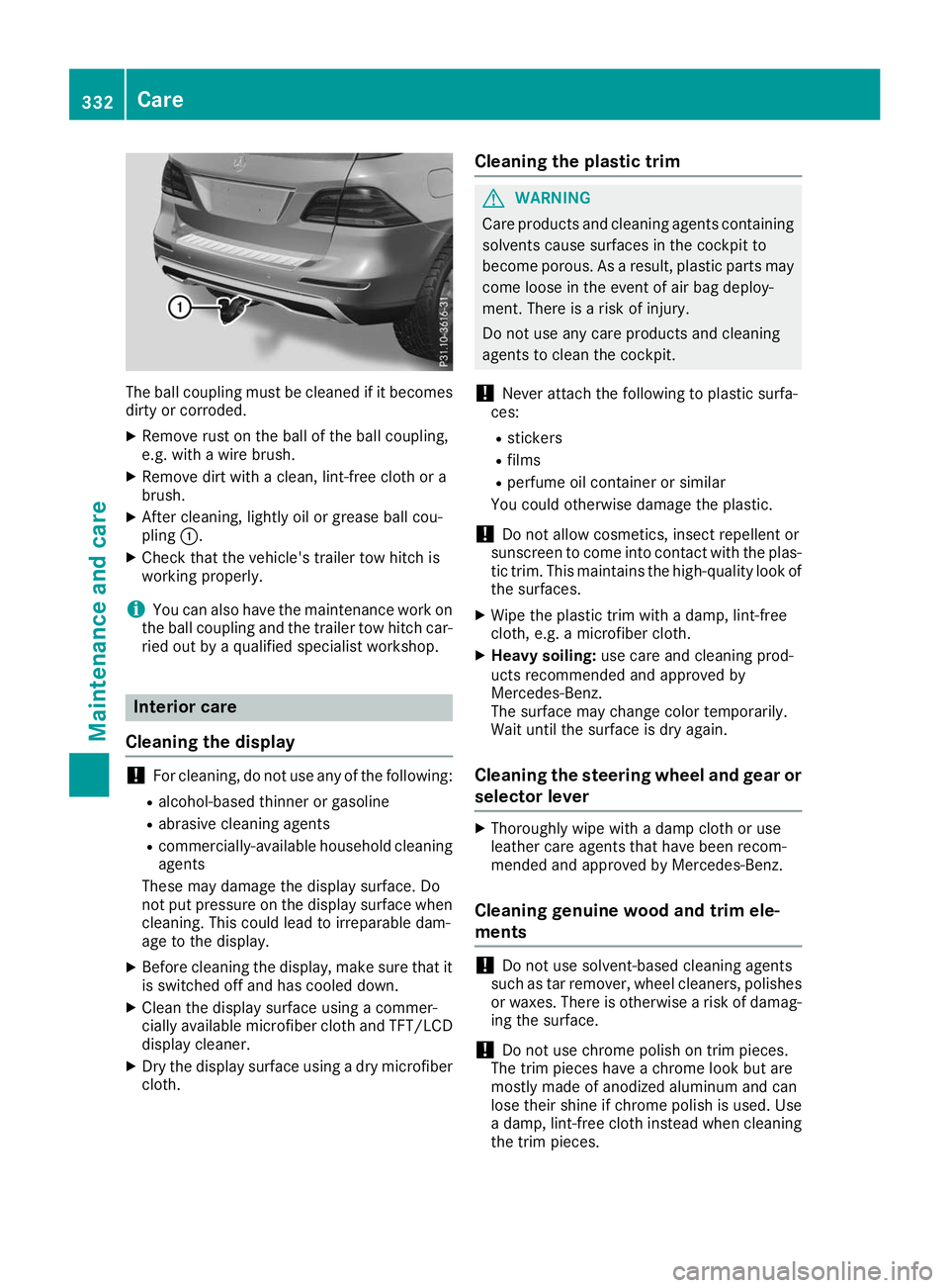
The ball coupling must be cleaned if it becomes
dirty or corroded.
X Remove rust on the ball of the ball coupling,
e.g. with a wire brush.
X Remove dirt with a clean, lint-free cloth or a
brush.
X After cleaning, lightly oil or grease ball cou-
pling 0043.
X Check that the vehicle's trailer tow hitch is
working properly.
i You can also have the maintenance work on
the ball coupling and the trailer tow hitch car-
ried out by a qualified specialist workshop. Interior care
Cleaning the display !
For cleaning, do not use any of the following:
R alcohol-based thinner or gasoline
R abrasive cleaning agents
R commercially-available household cleaning
agents
These may damage the display surface. Do
not put pressure on the display surface when
cleaning. This could lead to irreparable dam-
age to the display.
X Before cleaning the display, make sure that it
is switched off and has cooled down.
X Clean the display surface using a commer-
cially available microfiber cloth and TFT/LCD
display cleaner.
X Dry the display surface using a dry microfiber
cloth. Cleaning the plastic trim G
WARNING
Care products and cleaning agents containing solvents cause surfaces in the cockpit to
become porous. As a result, plastic parts may
come loose in the event of air bag deploy-
ment. There is a risk of injury.
Do not use any care products and cleaning
agents to clean the cockpit.
! Never attach the following to plastic surfa-
ces:
R stickers
R films
R perfume oil container or similar
You could otherwise damage the plastic.
! Do not allow cosmetics, insect repellent or
sunscreen to come into contact with the plas-
tic trim. This maintains the high-quality look of the surfaces.
X Wipe the plastic trim with a damp, lint-free
cloth, e.g. a microfiber cloth.
X Heavy soiling: use care and cleaning prod-
ucts recommended and approved by
Mercedes-Benz.
The surface may change color temporarily.
Wait until the surface is dry again.
Cleaning the steering wheel and gear or selector lever X
Thoroughly wipe with a damp cloth or use
leather care agents that have been recom-
mended and approved by Mercedes-Benz.
Cleaning genuine wood and trim ele-
ments !
Do not use solvent-based cleaning agents
such as tar remover, wheel cleaners, polishes
or waxes. There is otherwise a risk of damag- ing the surface.
! Do not use chrome polish on trim pieces.
The trim pieces have a chrome look but are
mostly made of anodized aluminum and can
lose their shine if chrome polish is used. Use
a damp, lint-free cloth instead when cleaning the trim pieces. 332
CareMaintenance and care
Page 340 of 398
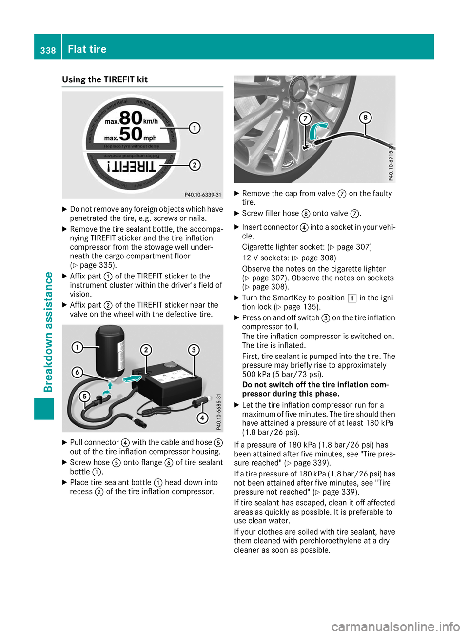
Using the TIREFIT kit
X
Do not remove any foreign objects which have
penetrated the tire, e.g. screws or nails.
X Remove the tire sealant bottle, the accompa-
nying TIREFIT sticker and the tire inflation
compressor from the stowage well under-
neath the cargo compartment floor
(Y page 335).
X Affix part 0043of the TIREFIT sticker to the
instrument cluster within the driver's field of
vision.
X Affix part 0044of the TIREFIT sticker near the
valve on the wheel with the defective tire. X
Pull connector 0085with the cable and hose 0083
out of the tire inflation compressor housing.
X Screw hose 0083onto flange 0084of tire sealant
bottle 0043.
X Place tire sealant bottle 0043head down into
recess 0044of the tire inflation compressor. X
Remove the cap from valve 006Bon the faulty
tire.
X Screw filler hose 006Conto valve 006B.
X Insert connector 0085into a socket in your vehi-
cle.
Cigarette lighter socket: (Y page 307)
12 V sockets: (Y page 308)
Observe the notes on the cigarette lighter
(Y page 307). Observe the notes on sockets
(Y page 308).
X Turn the SmartKey to position 0047in the igni-
tion lock (Y page 135).
X Press on and off switch 0087on the tire inflation
compressor to I.
The tire inflation compressor is switched on.
The tire is inflated.
First, tire sealant is pumped into the tire. The
pressure may briefly rise to approximately
500 kPa (5 bar/73 psi).
Do not switch off the tire inflation com-
pressor during this phase.
X Let the tire inflation compressor run for a
maximum of five minutes. The tire should then
have attained a pressure of at least 180 kPa
(1.8 bar/26 psi).
If a pressure of 180 kPa (1.8 bar/26 psi) has
been attained after five minutes, see "Tire pres- sure reached" (Y page 339).
If a tire pressure of 180 kPa (1.8 bar/26 psi) has not been attained after five minutes, see "Tire
pressure not reached" (Y page 339).
If tire sealant has escaped, clean it off affected
areas as quickly as possible. It is preferable to
use clean water.
If your clothes are soiled with tire sealant, have
them cleaned with perchloroethylene at a dry
cleaner as soon as possible. 338
Flat tireBreakdown assistance
Page 372 of 398
Speed rating
The speed rating is part of the tire identification. It specifies the speed range for which the tire is
approved.
GTW (Gross Trailer Weight)
The GTW is the weight of a trailer including the
weight of the load, luggage, accessories etc. on
the trailer.
GVW (Gross Vehicle Weight) The gross vehicle weight includes the weight of
the vehicle including fuel, tools, the spare wheel, accessories installed, occupants, luggage and
the drawbar noseweight, if applicable. The gross
vehicle weight must not exceed the gross vehi-
cle weight rating GVWR as specified on the vehi- cle identification plate on the B-pillar on the
driver's side.
GVWR (Gross Vehicle Weight Rating)
The GVWR is the maximum permissible gross
weight of a fully loaded vehicle (the weight of the
vehicle including all accessories, occupants,
fuel, luggage and the drawbar noseweight, if
applicable). The gross vehicle weight rating is
specified on the vehicle identification plate on
the B-pillar on the driver's side.
Maximum loaded vehicle weightThe maximum weight is the sum of:
R the curb weight of the vehicle
R the weight of the accessories
R the load limit
R the weight of the factory installed optional
equipment
Kilopascal (kPa) Metric unit for tire pressure. 6.9 kPa corre-
sponds to 1 psi. Another unit for tire pressure is
bar. 100 kilopascals (kPa) are the equivalent of
1 bar.
Load index
In addition to the load-bearing index, the load
index may also be imprinted on the sidewall of
the tire. This specifies the load-bearing capacity
more precisely.
Curb weight The weight of a vehicle with standard equipment
including the maximum capacity of fuel, oil and
coolant. It also includes the air-conditioning sys- tem and optional equipment if these are instal-
led in the vehicle, but does not include passen-
gers or luggage.
Maximum load rating The maximum tire load is the maximum permis-
sible weight in kilograms or lbs for which a tire is approved.
Maximum permissible tire pressure Maximum permissible tire pressure for one tire.
Maximum load on one tire
Maximum load on one tire. This is calculated by
dividing the maximum axle load of one axle by
two.
PSI (pounds per square inch) A standard unit of measure for tire pressure.
Aspect ratio Relationship between tire height and tire width
in percent.
Tire pressure
This is pressure inside the tire applying an out-
ward force to each square inch of the tire's sur-
face. The tire pressure is specified in pounds per
square inch (psi), in kilopascal (kPa) or in bar.
The tire pressure should only be corrected when the tires are cold.
Cold tire pressure
The tires are cold:
R if the vehicle has been parked with the tires
out of direct sunlight for at least three hours
and
R if the vehicle has not been driven further than
1 mile (1.6 km)
Tread The part of the tire that comes into contact with
the road.
BeadThe tire bead ensures that the tire sits securely
on the wheel. There are several steel wires in the
bead to prevent the tire from coming loose from
the wheel rim. 370
All about wheels and tiresWheels and tires
Page 374 of 398
be required earlier. Do not change the direction
of wheel rotation.
Clean the contact surfaces of the wheel and the
brake disc thoroughly every time a wheel is rota- ted. Check the tire pressure and, if necessary,
restart the tire pressure loss warning system or
the tire pressure monitor (Y page 358).Direction of rotation
Tires with a specified direction of rotation have
additional benefits, e.g. if there is a risk of hydro-
planing. These advantages can only be gained if the tires are installed corresponding to the
direction of rotation.
An arrow on the sidewall of the tire indicates itscorrect direction of rotation. Storing wheels
Store wheels that are not being used in a cool,
dry and preferably dark place. Protect the tires
from oil, grease, gasoline and diesel. Mounting a wheel
Preparing the vehicle X
Vehicle with emergency spare wheel:
when mounting the emergency spare wheel in
the event of a flat tire, follow the additional
notes on vehicle preparation under "Flat tire"
(Y page 335).
X Stop the vehicle on solid, non-slippery and
level ground.
X Apply the electric parking brake manually.
X Bring the front wheels into the straight-ahead
position.
X Vehicles with automatic transmission:
shift the transmission to position
005D.
X Vehicles with the AIRMATIC package:
make sure that the normal vehicle level is
selected (Y page 185).
X Vehicles with the Off-Road Engineering
package:
make sure that the normal vehicle
level is selected (Y page 179).
X Switch off the engine.
X Vehicles without KEYLESS-GO: remove the
SmartKey from the ignition lock. X
Vehicles with KEYLESS-GO: open the driv-
er's door.
The vehicle electronics are now in position
0092. This means no SmartKey is in the ignition
lock.
X Vehicles with KEYLESS-GO: remove the
Start/Stop button from the ignition lock
(Y page 135).
X Make sure that the engine cannot be started
via your smartphone (Y page 137).
X If included in the vehicle equipment, remove
the tire-change tool kit from the vehicle.
X Safeguard the vehicle against rolling away.
i Apart from certain country-specific varia-
tions, vehicles are not equipped with a tire-
change tool kit. For more information on
which tools are required to perform a wheel
change on your vehicle, consult a qualified
specialist workshop.
Necessary tire-changing tools can include, for
example:
R Jack
R Wheel chock
R Lug wrench
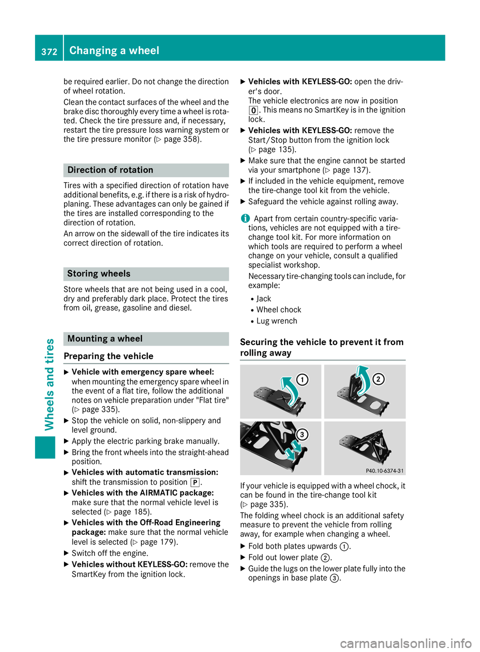
Securing the vehicle to prevent it from
rolling away If your vehicle is equipped with a wheel chock, it
can be found in the tire-change tool kit
(Y page 335).
The folding wheel chock is an additional safety
measure to prevent the vehicle from rolling
away, for example when changing a wheel.
X Fold both plates upwards 0043.
X Fold out lower plate 0044.
X Guide the lugs on the lower plate fully into the
openings in base plate 0087.372
Changing a wheelWheels and tires