width MERCEDES-BENZ GLE SUV 2019 Owner's Manual
[x] Cancel search | Manufacturer: MERCEDES-BENZ, Model Year: 2019, Model line: GLE SUV, Model: MERCEDES-BENZ GLE SUV 2019Pages: 398, PDF Size: 12.25 MB
Page 179 of 398
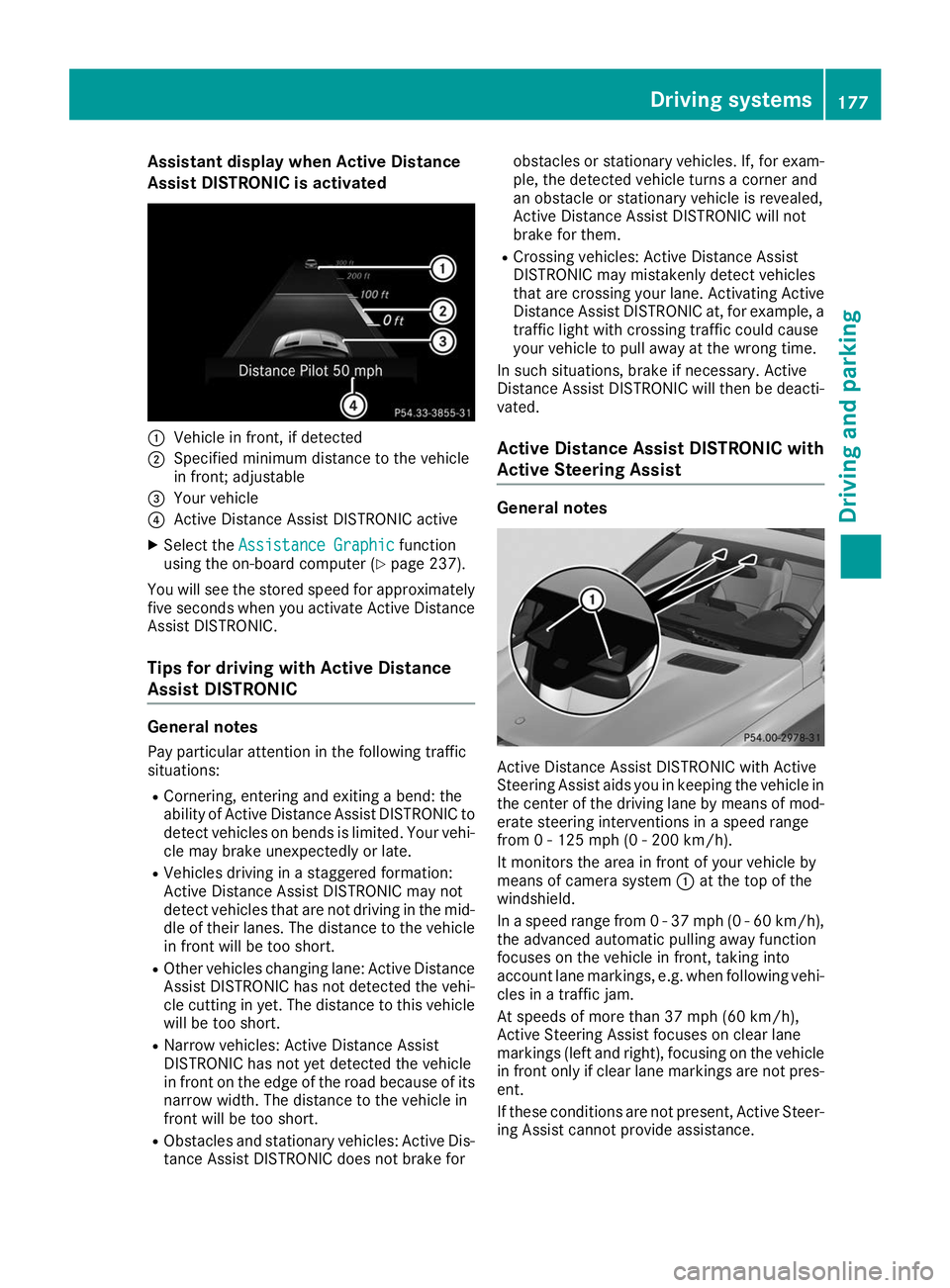
Assistant display when Active Distance
Assist DISTRONIC is activated 0043
Vehicle in front, if detected
0044 Specified minimum distance to the vehicle
in front; adjustable
0087 Your vehicle
0085 Active Distance Assist DISTRONIC active
X Select the Assistance Graphic
Assistance Graphic function
using the on-board computer (Y page 237).
You will see the stored speed for approximately five seconds when you activate Active Distance
Assist DISTRONIC.
Tips for driving with Active Distance
Assist DISTRONIC General notes
Pay particular attention in the following traffic
situations:
R Cornering, entering and exiting a bend: the
ability of Active Distance Assist DISTRONIC to detect vehicles on bends is limited. Your vehi-cle may brake unexpectedly or late.
R Vehicles driving in a staggered formation:
Active Distance Assist DISTRONIC may not
detect vehicles that are not driving in the mid- dle of their lanes. The distance to the vehiclein front will be too short.
R Other vehicles changing lane: Active Distance
Assist DISTRONIC has not detected the vehi-
cle cutting in yet. The distance to this vehicle
will be too short.
R Narrow vehicles: Active Distance Assist
DISTRONIC has not yet detected the vehicle
in front on the edge of the road because of its
narrow width. The distance to the vehicle in
front will be too short.
R Obstacles and stationary vehicles: Active Dis-
tance Assist DISTRONIC does not brake for obstacles or stationary vehicles. If, for exam-
ple, the detected vehicle turns a corner and
an obstacle or stationary vehicle is revealed,
Active Distance Assist DISTRONIC will not
brake for them.
R Crossing vehicles: Active Distance Assist
DISTRONIC may mistakenly detect vehicles
that are crossing your lane. Activating Active
Distance Assist DISTRONIC at, for example, a
traffic light with crossing traffic could cause
your vehicle to pull away at the wrong time.
In such situations, brake if necessary. Active
Distance Assist DISTRONIC will then be deacti-
vated.
Active Distance Assist DISTRONIC with
Active Steering Assist General notes
Active Distance Assist DISTRONIC with Active
Steering Assist aids you in keeping the vehicle in
the center of the driving lane by means of mod-
erate steering interventions in a speed range
from 0 - 125 mph (0 - 200 km/h).
It monitors the area in front of your vehicle by
means of camera system 0043at the top of the
windshield.
In a speed range from 0 - 37 mph (0 - 60 km/h),
the advanced automatic pulling away function
focuses on the vehicle in front, taking into
account lane markings, e.g. when following vehi-
cles in a traffic jam.
At speeds of more than 37 mph (60 km/h),
Active Steering Assist focuses on clear lane
markings (left and right), focusing on the vehicle
in front only if clear lane markings are not pres-
ent.
If these conditions are not present, Active Steer-
ing Assist cannot provide assistance. Driving systems
177Driving and parking Z
Page 198 of 398
R
if the camera lens is dirty or obstructed.
Observe the notes on cleaning
(Y page 331)
R if the rear of your vehicle is damaged. In this
event, have the camera position and setting
checked at a qualified specialist workshop
The field of vision and other functions of the rear
view camera may be restricted due to additional
accessories on the rear of the vehicle (e.g.
license plate holder, bicycle rack).
For technical reasons, leaving the standard
height can result in inaccuracies in the guide
lines on vehicles with a height-adjustable chas-
sis.
i The rear view camera is protected from rain-
drops and dust by means of a flap. When the
rear view camera is activated, this flap opens.
The flap closes again when:
R you have finished the maneuvering process
R you switch off the engine
R you open the cargo compartment
Observe the notes on cleaning (Y page 331).
For technical reasons, the flap may remain
open briefly after the rear view camera has
been deactivated.
Activating/deactivating the rear view camera X
To activate: make sure that the SmartKey is
in position 0048in the ignition lock.
X Make sure that the Activation by R gear Activation by R gear
function is selected in the multimedia system (see the Digital Operator's Manual).
X Engage reverse gear.
The rear view camera flap opens. The multi-
media system shows the area behind the vehi-
cle with guide lines.
The image from the rear view camera is avail-
able throughout the maneuvering process.
X To switch the function mode for vehicles
with trailer tow hitch: using the controller,
select symbol 0043for the "Reverse parking"
function or symbol 0044for "Coupling up a
trailer".
The symbol of the selected function is high-
lighted.
To deactivate: the rear view camera deacti-
vates if you shift the transmission to 005Dor after
driving forwards a short distance. Displays in the multimedia system The rear view camera may show a distorted view
of obstacles, show them incorrectly or not at all.
The rear view camera does not show objects in
the following positions:
R very close to the rear bumper
R under the rear bumper
R in the area immediately above the tailgate
handle
! Objects not at ground level may appear to
be further away than they actually are, e.g.:
R the bumper of a parked vehicle
R the drawbar of a trailer
R the ball coupling of a trailer tow hitch
R the rear section of an HGV
R a slanted post
Use the guidelines only for orientation.
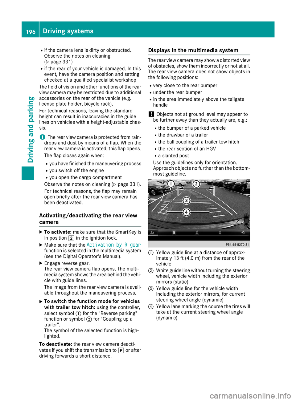
Approach objects no further than the bottom- most guideline. 0043
Yellow guide line at a distance of approx-
imately 13 ft (4.0 m) from the rear of the
vehicle
0044 White guide line without turning the steering
wheel, vehicle width including the exterior
mirrors (static)
0087 Yellow guide line for the vehicle width
including the exterior mirrors, for current
steering wheel angle (dynamic)
0085 Yellow lane marking the course the tires will
take at the current steering wheel angle
(dynamic) 196
Driving systemsDriving and parking
Page 199 of 398
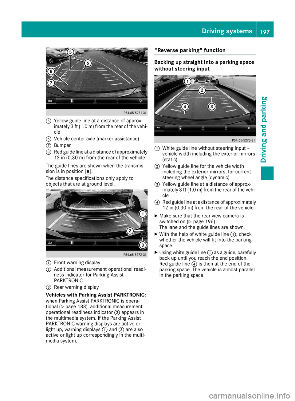
0083
Yellow guide line at a distance of approx-
imately 3 ft (1.0 m) from the rear of the vehi-
cle
0084 Vehicle center axle (marker assistance)
006B Bumper
006C Red guide line at a distance of approximately
12 in (0.30 m) from the rear of the vehicle
The guide lines are shown when the transmis-
sion is in position 005E.
The distance specifications only apply to
objects that are at ground level. 0043
Front warning display
0044 Additional measurement operational readi-
ness indicator for Parking Assist
PARKTRONIC
0087 Rear warning display
Vehicles with Parking Assist PARKTRONIC:
when Parking Assist PARKTRONIC is opera-
tional (Y page 188), additional measurement
operational readiness indicator 0044appears in
the multimedia system. If the Parking Assist
PARKTRONIC warning displays are active or
light up, warning displays 0043and 0087are also
active or light up correspondingly in the multi-
media system. "Reverse parking" function Backing up straight into a parking space
without steering input
0043
White guide line without steering input –
vehicle width including the exterior mirrors
(static)
0044 Yellow guide line for the vehicle width
including the exterior mirrors, for current
steering wheel angle (dynamic)
0087 Yellow guide line at a distance of approx-
imately 3 ft (1.0 m) from the rear of the vehi-
cle
0085 Red guide line at a distance of approximately
12 in (0.30 m) from the rear of the vehicle
X Make sure that the rear view camera is
switched on (Y page 196).
The lane and the guide lines are shown.
X With the help of white guide line 0043, check
whether the vehicle will fit into the parking
space.
X Using white guide line 0043as a guide, carefully
back up until you reach the end position.
Red guide line 0085is then at the end of the
parking space. The vehicle is almost parallel
in the parking space. Driving systems
197Driving and parking Z
Page 200 of 398
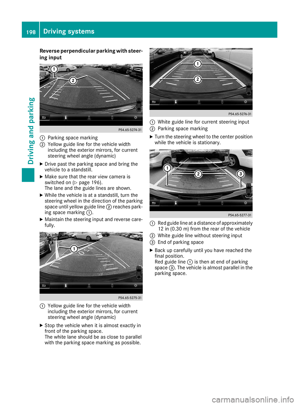
Reverse perpendicular parking with steer-
ing input 0043
Parking space marking
0044 Yellow guide line for the vehicle width
including the exterior mirrors, for current
steering wheel angle (dynamic)
X Drive past the parking space and bring the
vehicle to a standstill.
X Make sure that the rear view camera is
switched on (Y page 196).
The lane and the guide lines are shown.
X While the vehicle is at a standstill, turn the
steering wheel in the direction of the parking
space until yellow guide line 0044reaches park-
ing space marking 0043.
X Maintain the steering input and reverse care-
fully. 0043
Yellow guide line for the vehicle width
including the exterior mirrors, for current
steering wheel angle (dynamic)
X Stop the vehicle when it is almost exactly in
front of the parking space.
The white lane should be as close to parallel
with the parking space marking as possible. 0043
White guide line for current steering input
0044 Parking space marking
X Turn the steering wheel to the center position
while the vehicle is stationary. 0043
Red guide line at a distance of approximately
12 in (0.30 m) fromthe rear of the vehicle
0044 White guide line without steering input
0087 End of parking space
X Back up carefully until you have reached the
final position.
Red guide line 0043is then at end of parking
space 0087. The vehicle is almost parallel in the
parking space. 198
Driving systemsDriving an
d parking
Page 204 of 398
R
the rear section of an HGV
R a slanted post
Use the guidelines only for orientation.
Approach objects no further than the bottom- most guideline.
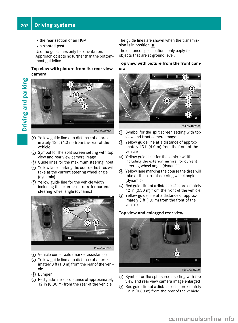
Top view with picture from the rear view
camera 0043
Yellow guide line at a distance of approx-
imately 13 ft (4.0 m) fromthe rear of the
vehicle
0044 Symbol for the split screen setting with top
view and rear view camera image
0087 Guide lines for the maximum steering input
0085 Yellow lane marking the course the tires will
take at the current steering wheel angle
(dynamic)
0083 Yellow guide line for the vehicle width
including the exterior mirrors, for current
steering wheel angle (dynamic) 0084
Vehicle center axle (marker assistance)
006B Yellow guide line at a distance of approx-
imately 3 ft (1.0 m) fromthe rear of the vehi-
cle
006C Bumper
006D Red guide line at a distance of approximately
12 in (0.30 m) fromthe rear of the vehicle The guide lines are shown when the transmis-
sion is in position
005E.
The distance specifications only apply to
objects that are at ground level.
Top view with picture from the front cam-
era 0043
Symbol for the split screen setting with top
view and front camera image
0044 Yellow guide line at a distance of approx-
imately 13 ft (4.0 m) fromthe front of the
vehicle
0087 Yellow guide line for the vehicle width
including the exterior mirrors, for current
steering wheel angle (dynamic)
0085 Yellow lane marking the course the tires will
take at the current steering wheel angle
(dynamic)
0083 Red guide line at a distance of approximately
12 in (0.30 m) fromthe front of the vehicle
0084 Yellow guide line at a distance of approx-
imately 3 ft (1.0 m) fromthe front of the
vehicle
Top view and enlarged rear view 0043
Symbol for the split screen setting with top
view and rear view camera image enlarged
0044 Red guide line at a distance of approximately
12 in (0.30 m)from the rear of the vehicle 202
Driving systemsDriving and parking
Page 205 of 398
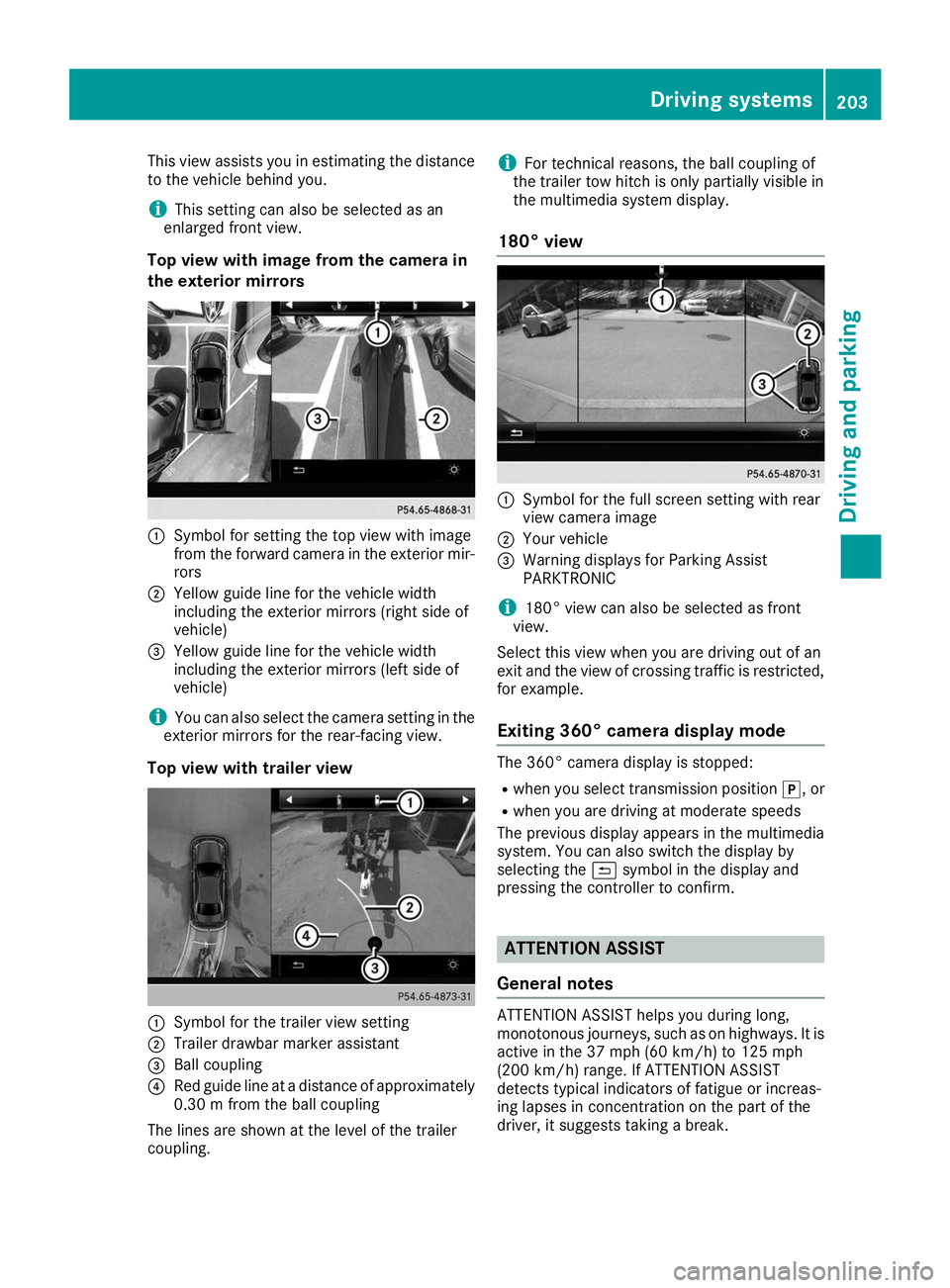
This view assists you in estimating the distance
to the vehicle behind you.
i This setting can also be selected as an
enlarged front view.
Top view with image from the camera in
the exterior mirrors 0043
Symbol for setting the top view with image
from the forward camera in the exterior mir-
rors
0044 Yellow guide line for the vehicle width
including the exterior mirrors (right side of
vehicle)
0087 Yellow guide line for the vehicle width
including the exterior mirrors (left side of
vehicle)
i You can also select the camera setting in the
exterior mirrors for the rear-facing view.
Top view with trailer view 0043
Symbol for the trailer view setting
0044 Trailer drawbar marker assistant
0087 Ball coupling
0085 Red guide line at a distance of approximately
0.30 m from the ball coupling
The lines are shown at the level of the trailer
coupling. i
For technical reasons, the ball coupling of
the trailer tow hitch is only partially visible in
the multimedia system display.
180° view 0043
Symbol for the full screen setting with rear
view camera image
0044 Your vehicle
0087 Warning displays for Parking Assist
PARKTRONIC
i 180° view can also be selected as front
view.
Select this view when you are driving out of an
exit and the view of crossing traffic is restricted,
for example.
Exiting 360° camera display mode The 360° camera display is stopped:
R
when you select transmission position 005D, or
R when you are driving at moderate speeds
The previous display appears in the multimedia
system. You can also switch the display by
selecting the 0039symbol in the display and
pressing the controller to confirm. ATTENTION ASSIST
General notes ATTENTION ASSIST helps you during long,
monotonous journeys, such as on highways. It is
active in the 37 mph (60 km/h) to 125 mph
(200 km/h) range. If ATTENTION ASSIST
detects typical indicators of fatigue or increas-
ing lapses in concentration on the part of the
driver, it suggests taking a break. Driving systems
203Driving and parking Z
Page 225 of 398
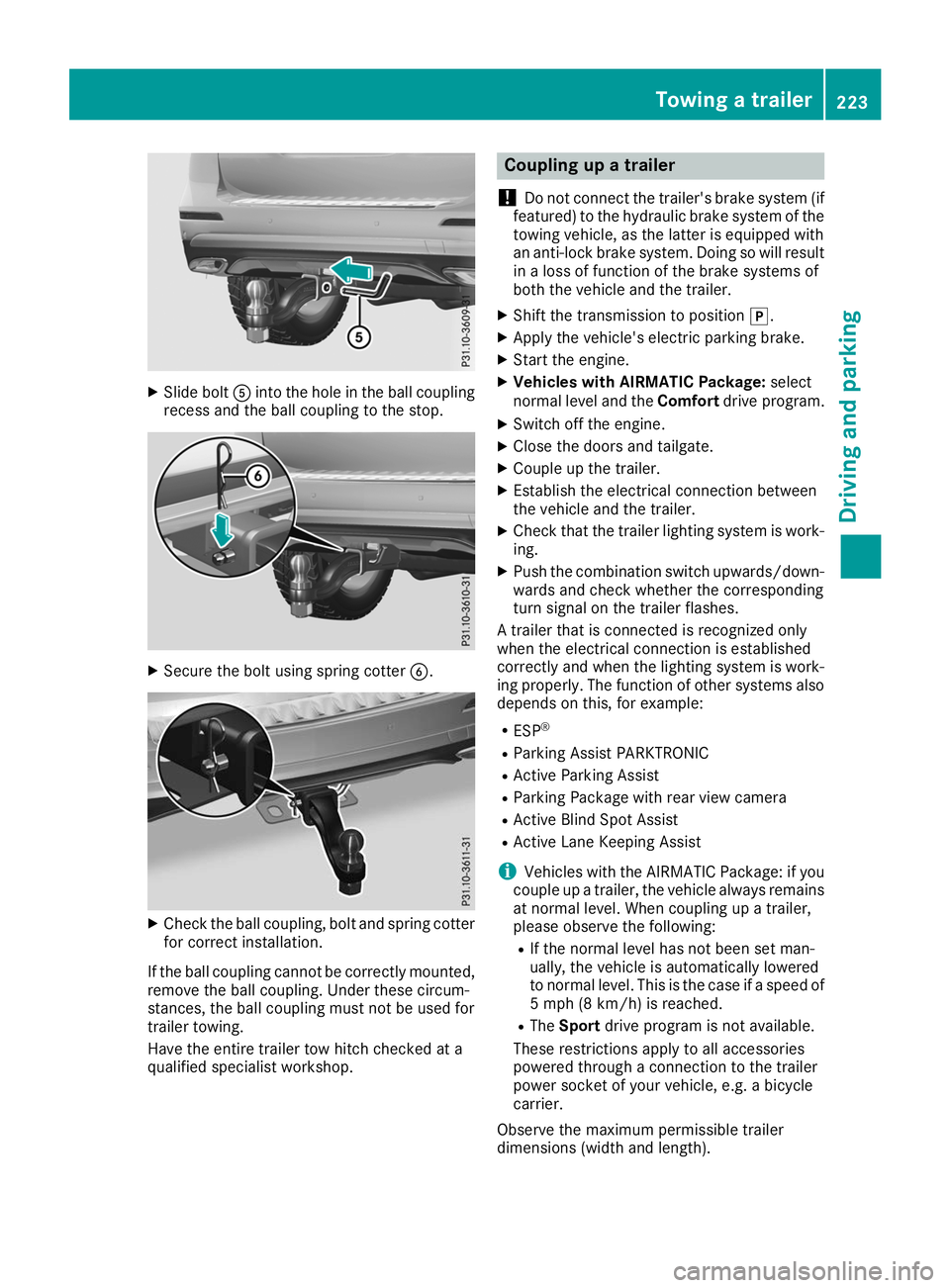
X
Slide bolt 0083into the hole in the ball coupling
recess and the ball coupling to the stop. X
Secure the bolt using spring cotter 0084.X
Check the ball coupling, bolt and spring cotter
for correct installation.
If the ball coupling cannot be correctly mounted,
remove the ball coupling. Under these circum-
stances, the ball coupling must not be used for
trailer towing.
Have the entire trailer tow hitch checked at a
qualified specialist workshop. Coupling up a trailer
! Do not connect the trailer's brake system (if
featured) to the hydraulic brake system of the towing vehicle, as the latter is equipped with
an anti-lock brake system. Doing so will result
in a loss of function of the brake systems of
both the vehicle and the trailer.
X Shift the transmission to position 005D.
X Apply the vehicle's electric parking brake.
X Start the engine.
X Vehicles with AIRMATIC Package: select
normal level and the Comfortdrive program.
X Switch off the engine.
X Close the doors and tailgate.
X Couple up the trailer.
X Establish the electrical connection between
the vehicle and the trailer.
X Check that the trailer lighting system is work-
ing.
X Push the combination switch upwards/down-
wards and check whether the corresponding
turn signal on the trailer flashes.
A trailer that is connected is recognized only
when the electrical connection is established
correctly and when the lighting system is work-
ing properly. The function of other systems also depends on this, for example:
R ESP ®
R Parking Assist PARKTRONIC
R Active Parking Assist
R Parking Package with rear view camera
R Active Blind Spot Assist
R Active Lane Keeping Assist
i Vehicles with the AIRMATIC Package: if you
couple up a trailer, the vehicle always remains
at normal level. When coupling up a trailer,
please observe the following:
R If the normal level has not been set man-
ually, the vehicle is automatically lowered
to normal level. This is the case if a speed of
5 mph (8 km/h) is reached.
R The Sport drive program is not available.
These restrictions apply to all accessories
powered through a connection to the trailer
power socket of your vehicle, e.g. a bicycle
carrier.
Observe the maximum permissible trailer
dimensions (width and length). Towing a trailer
223Driving and parking Z
Page 328 of 398
A qualified specialist workshop will reset the
ASSYST PLUS service interval display after the
service work has been carried out. You can also obtain further information on maintenance
work, for example.
Special service requirements The specified maintenance interval takes only
the normal operation of the vehicle into
account. Under increased load on the vehicle,
maintenance work must be carried out more
frequently, for example:
R Regular city driving with frequent intermedi-
ate stops
R If the vehicle is primarily used to travel short
distances
R Use in mountainous terrain or on poor road
surfaces
R If the engine is often left idling for long periods
Under these or similar conditions, have, for
example, the air filter, engine oil and oil filter
replaced or changed more frequently. Under
arduous operating conditions, the tires must be
checked more often. Further information can be
obtained at a qualified specialist workshop.
Driving abroad An extensive Mercedes-Benz Service network is
also available in other countries. You can obtain further information from any authorized
Mercedes-Benz Center. Care
General notes
H
Environmental note
Dispose of empty packaging and cleaning
cloths in an environmentally responsible man-
ner.
! When cleaning your car, do not use:
R dry, coarse or hard cloths
R abrasive cleaning agents
R solvents
R cleaning agents containing solvents
Do not scrub.
Do not touch the surfaces and films with hard objects, e.g. rings or ice scrapers. Otherwise, you may scratch or damage the surfaces and
films.
! Do not park your vehicle for a long period of
time directly after cleaning, particularly after
cleaning the wheel rim with wheel cleaner.
Wheel cleaner can lead to the increased cor-
rosion of the brake discs and pads. Therefore,
drive for a few minutes after cleaning. By
heating up the brakes, the brake discs and
pads dry. The vehicle can then be parked for a
long period of time.
Regular care of your vehicle is a condition for
retaining the quality in the long term.
Use care products and cleaning agents recom-
mended and approved by Mercedes-Benz. Washing the vehicle and cleaning the
paintwork
Automatic car wash G
WARNING
Braking efficiency is reduced after washing
the vehicle. There is a risk of an accident.
After the vehicle has been washed, brake
carefully while paying attention to the traffic
conditions until full braking power is restored.
! Before driving into an automatic car wash,
make sure that it is suitable for the dimen-
sions of the vehicle. In particular, make sure
that:
R there is enough ground clearance between
the vehicle underbody and the guide rails of the automatic car wash.
R the clearance width of the automatic car
wash is sufficient, particularly the width of
the guide rails.
R you enter the automatic car wash straight
and in the center of the guide rails in order
to avoid damaging the tires or wheel rims.
Fold in the exterior mirrors before the vehicle
is washed. The exterior mirrors could other-
wise be damaged.
! When Active Distance Assist DISTRONIC or
the HOLD function is activated, the vehicle
brakes automatically in certain situations. 326
CareMaintenance and care
Page 354 of 398
Pay particular attention to damage such as:
R Cuts in the tires
R Punctures in the tires
R Tears in the tires
R Bulges on tires
R Deformation or severe corrosion on wheels
Regularly check the tire tread depth and the
condition of the tread across the whole width of
all tires (Y page 352). If necessary, turn the
front wheels to full lock in order to inspect the
inner side of the tire surface.
All wheels must have a valve cap to protect the
valve against dirt and moisture. Do not mount
anything onto the valve other than the standard
valve cap or other valve caps approved by
Mercedes-Benz for your vehicle. Do not use any other valve caps or systems, e.g. tire pressure
monitoring systems.
Regularly check the pressure of all the tires par- ticularly prior to long trips. Adjust the tire pres-
sure as necessary (Y page 354).
Observe the notes on the emergency spare
wheel (Y page 376).
The service life of tires depends, among other
things, on the following factors:
R Driving style
R Tire pressure
R Distance covered Notes on tire tread
G
WARNING
Insufficient tire tread will reduce tire traction.
The tire is no longer able to dissipate water.
This means that on wet road surfaces, the risk of hydroplaning increases, in particular where speed is not adapted to suit the driving con-
ditions. There is a risk of accident.
If the tire pressure is too high or too low, tires
may exhibit different levels of wear at differ-
ent locations on the tire tread. Thus, you
should regularly check the tread depth and
the condition of the tread across the entire
width of all tires.
Minimum tire tread depth for:
R Summer tires: 00CEin (3 mm)
R M+S tires: 00CFin (4 mm) For safety reasons, replace the tires before
the legally prescribed limit for the minimum
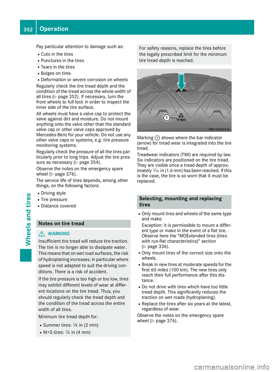
tire tread depth is reached. Marking
0043shows where the bar indicator
(arrow) for tread wear is integrated into the tire
tread.
Treadwear indicators (TWI) are required by law. Six indicators are positioned on the tire tread.
They are visible once a tread depth of approx-
imately 00CDin (1.6 mm) has been reached. If this
is the case, the tire is so worn that it must be
replaced. Selecting, mounting and replacing
tires
R Only mount tires and wheels of the same type
and make.
Exception: it is permissible to mount a differ-
ent type or make in the event of a flat tire.
Observe here the "MOExtended tires (tires
with run-flat characteristics)" section
(Y page 336).
R Only mount tires of the correct size onto the
wheels.
R Break in new tires at moderate speeds for the
first 60 miles (100 km). The new tires only
reach their full performance after this dis-
tance.
R Do not drive with tires which have too little
tread depth. This significantly reduces the
traction on wet roads (hydroplaning).
R Replace the tires after six years at the latest,
regardless of wear.
Observe the notes on the emergency spare
wheel (Y page 376). 352
OperationWheels and tires
Page 366 of 398
Step 3
Example 1 Example 2 Example 3
Permissible load (maxi-
mum gross vehicle
weight rating from the
Tire and Loading Infor-
mation placard minus
the gross weight of all
occupants)
1500 lbs (680 kg)
00F8
750 lbs (340 kg) =
750 lbs (340 kg) 1500 lbs (680 kg)
00F8
540 lbs (245 kg)
=960 lbs (435 kg) 1500 lbs (680 kg)
00F8
150 lbs (68 kg) =
1350 lbs (612 kg) Vehicle identification plate
Even if you have calculated the total cargo care-
fully, you should still make sure that the gross
vehicle weight rating and the gross axle weight
rating are not exceeded. Details can be found on
the vehicle identification plate on the B-pillar on
the driver's side of the vehicle (Y page 361).
Permissible Gross Vehicle Weight Rating
(GVWR): the gross weight of the vehicle, all pas-
sengers, load and trailer load/noseweight (if
applicable) must not exceed the permissible
gross vehicle weight.
Gross Axle Weight Rating (GAWR): the maxi-
mum permissible weight that can be carried by
one axle (front or rear axle).
To ensure that your vehicle does not exceed the maximum permissible values (gross vehicle
weight and maximum gross axle weight rating),
have your loaded vehicle (including driver, occu-
pants, cargo, and full trailer load if applicable)
weighed on a suitable vehicle weighbridge. Trailer load/noseweight
The trailer load/noseweight affects the gross
weight of the vehicle. If a trailer is attached, the trailer load/noseweight is included in the load
along with occupants and luggage. The trailer
load/noseweight is usually approximately 8% of
the gross weight of the trailer and its cargo. All about wheels and tires
Uniform Tire Quality Grading Stand-
ards
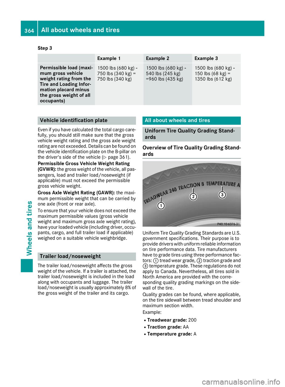
Overview of Tire Quality Grading Stand- ards Uniform Tire Quality Grading Standards are U.S.
government specifications. Their purpose is to
provide drivers with uniform reliable information on tire performance data. Tire manufacturers
have to grade tires using three performance fac-
tors: 0043tread wear grade, 0044traction grade and
0087 temperature grade. These regulations do not
apply to Canada. Nevertheless, all tires sold in
North America are provided with the corre-
sponding quality grading markings on the side-
wall of the tire.
Quality grades can be found, where applicable,
on the tire sidewall between tread shoulder and
maximum section width.
Example:
R Treadwear grade: 200
R Traction grade: AA
R Temperature grade: A364
All about wheels and tiresWheels and tires