light MERCEDES-BENZ GLE SUV 2019 Owners Manual
[x] Cancel search | Manufacturer: MERCEDES-BENZ, Model Year: 2019, Model line: GLE SUV, Model: MERCEDES-BENZ GLE SUV 2019Pages: 681, PDF Size: 11.7 MB
Page 519 of 681
St
arting assi stance and charging the12 V
battery Re
quirements:
R The vehicle is secured with the electric park‐
ing brake.
R Vehicles with automatic transmission: the
transmission is in position j.
R The ignition and all electrical consumers are
switched off.
R The bonnet is open. #
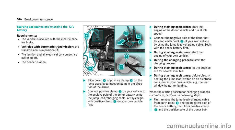
Slide co ver1 of positive clamp 2onthe
jump-s tarting connection point in the direc‐
tion of the ar row. #
Connect positive clamp 2onyour vehicle to
th e positive pole of the donor battery using
th e jump lead/charging cable. Alw ays begin
with positive clamp 2onyour ow nve hicle
fi rs t. #
During starting assi stance: start the
engine of the donor vehicle and run at idle
speed. #
Connect the negative pole of the donor bat‐
te ry and ear thpoint 3ofyour ow nve hicle
by using the jump lead/charging cable. Begin
with the donor battery firs t. #
During starting assi stance: start the
engine of your ow nve hicle. #
During thech arging process: start the
ch arging process. #
During starting assi stance: letthe engines
ru nfo r se veral minutes. #
During starting assi stance: before discon‐
necting the jump lead, switch on an electrical
consumer in your ow nve hicle, e.g. there ar
wind owheater or lighting.
When thest arting assis tance/charging process
is compl ete, per form thefo llowing steps: #
First,re mo vethe jump lead/charging cable
from ear thpoint 3and the negative pole of
th e donor batter y,then from positive clamp
2 and the positive pole of the donor bat‐ 516
Breakdown assis tance
Page 530 of 681
#
Check whe ther the wheel or valve has a
leak. #
Ifyo u are unable torectify the damage,
conta ct aqualified specialist workshop. Information on
there commended tyre pressure
fo rth eve hicle's factor y-fitted tyres can be found
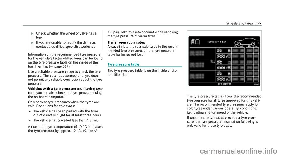
on the tyre pressure table on the inside of the
fuel filler flap (→ page 527).
Use a suitable pressure gauge tocheck the tyre
pressure. The outer appearance of a tyre does
not permit any reliable conclusion about the tyre
pressure.
Ve hicles with a tyre pressure monitoring sys‐
te m: you can also check the tyre pressure using
th e on-board computer.
Only cor rect tyre pressures when the tyres are
cold. Conditions for cold tyres:
R The vehicle has been par ked with the tyres
out of direct sunlight for at least thre e hours.
R The vehicle has tr avelled less than 1.6 km.
A rise in the tyre temp erature of 10°C increases
th e tyre pressure byappr ox.10 kPa (0.1 bar/ 1.
5 psi). Take this into account when checking
th e tyre pressure of warm tyres.
Tr ailer operation no tes
Alw ays inflate there ar axle tyres tothere com‐
mended tyre pressures on the tyre pressure
ta ble for increased load. Ty
re pressure table The tyre pressure
table is on the inside of the
fuel filler flap. The tyre pressure
table sho ws there commended
tyre pressure for all tyres appro vedfo rth is vehi‐
cle. The recommended tyre pressures apply for
cold tyres under various operating conditions,
i.e. loading and/or speed of theve hicle.
If one or more tyre sizes precede a tyre pres‐
sure, the tyre pressure information following is
only valid forth ose tyre sizes. Wheels and tyres
527
Page 531 of 681
If
th e preceding tyre sizes are complemented by
th e+ symbol, the tyre pressure information
fo llowing sho wsalternative tyre pressures.
These tyre pressures may impr oveyour vehicle's
ri de comfort. Fuel consum ption may then
increase slightl y.
The load conditions "partially laden" and "fully
laden" are defined in theta ble for dif fere nt num‐
be rs of passengers and amounts of luggage. The
actual number of seats may dif fer from this.
Be sure toalso obse rveth efo llowing fur ther
re lated subjects:
R Notes on tyre pressure (→ page 526)Ty
re pressure moni toring sy stem Fu
nction of the ty repressure moni toring sys‐
tem
The sy stem checks the tyre pressure and the
tyre temp erature of the tyres fitted totheve hicle
by means of a tyre pressu resensor.
New tyre pressure sensors, e.g. in winter tyres,
are automatically taught-in during thefirs t jour‐
ney they are used. The tyre pressure and
the tyre temp erature
appear in the multifunction display
(→ page 528).
If th ere is a subs tantial pressure loss or if the
tyre temp erature is excessive, you will be
wa rned in thefo llowing ways:
R via display messa ges (→ page 600)
R viatheh warning lamp in the instrument
clus ter (→ page 628)
The tyre pressu remonitoring sy stem is only an
aid. It is the driver's responsibility toset the tyre
pressure tothere commended cold tyre pressure
suitable forth e operating situation. Set the tyre
pressure for cold tyres using a tyre pressu re
ga uge. Notethat the cor rect tyre pressure for
th e cur rent operating situation mu stfirs t be
tau ght-in tothe tyre pressure monitoring sys‐
te m.
In most cases, the tyre pressure monitoring sys‐
te m will auto matically update the new refere nce
va lues af teryo u ha vechanged the tyre pressure.
Yo u can, ho wever,also update there fere nce val‐
ues byrestarting the tyre pressure monitoring
sy stem manually (→ page 529). Sy
stem limitations
The sy stem may be impaired or may not function
in thefo llowing situations:
R ifth e tyre pressure is set incor rectly
R ifth ere is a sudden pressure loss caused, for
ex ample, byafo re ign object penetrating the
tyre
R ifth ere is a malfunction caused byano ther
ra dio signal source
Make sure toobser vethefo llowing fur ther rela‐
te d subjec t:
R notes on tyre pressure (→ page 526)
Checking the ty repressure with the tyre
pressure moni toring sy stem
Requ irements:
R The ignition is switched on.
On-board computer: , Service .
Tyres
One of thefo llowing displa ysappears:
R Cur rent tyre pressure and tyre temp erature
of the individual wheels: 528
Wheels and tyres
Page 550 of 681
#
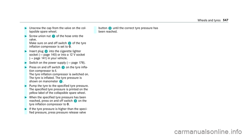
Unscr ew the cap from theva lve on the col‐
lapsible spare wheel. #
Screw union nut 1ofthe hose onto the
va lve.
Make sure on and off switch 3ofthe tyre
inflation compressor is set to0. #
Insert plug 4into the cigar ette lighter
soc ket (→ page 140) or into a 12V soc ket
( → page 141) in your vehicle. #
Switch on the po wer supp ly (→page 178). #
Press on and off switch 3onthe tyre infla‐
tion compressor toI.
The tyre inflation compressor is switched on.
The tyre is inflated. The tyre pressure is
shown on manome ter2. #
Pump the tyre tothe specified tyre pressure.
The specified tyre pressure is printed on the
ye llow label of the collapsible spare wheel. #
When the specified tyre pressure has been
re ached, press on and off swit ch3 onthe
tyre inflation compressor to0. #
Ifth e tyre pressure is higher than the speci‐
fi ed pressure, press pressure release valve but
ton5 until the cor rect tyre pressure has
been reached. Wheels and tyres
547
Page 562 of 681
*
NO
TEOverheating at high outside tem‐
peratures If an inapp
ropriate coolant is used, the
engine cooling sy stem is not suf ficiently pro‐
te cted against overheating and cor rosion at
high outside temp eratures. #
Alw ays use coolant appr ovedby
Mercedes-Benz. #
Obser vethe instructions in the
Mercedes-Benz Specifications for Oper‐
ating Fluids 310.1. Ha
ve the coolant regularly replaced at a qualified
specialist workshop.
The proportion of cor rosion inhibitor/antifreeze
concentrate in the engine cooling sy stem should
be:
R a minimum of 50% (antifreeze pr otection
down toappr oximately -37 °C)
R a maximum of 55% (antifreeze pr otection
down to-45 °C) Note
s on windscreen washer fluid Obser
vethe no tes on operating fluids
(→ page 552). &
WARNING ‑ Risk of fire and injury due to
windscreen washer concentrate
Wi ndsc reen washer concentrate is highly
fl ammable. It could ignite if it comes into
con tact wi thhot engine component parts or
th eex haust sy stem. #
Make sure that no windsc reen washer
concentrate spills out next tothefiller
opening. *
NO
TEDama getotheex terior lighting
due tounsuitable windsc reen washer
fl uid Uns
uitable windsc reen washer fluids may
damage the plastic sur face of theex terior
lighting. #
Only use windscreen washer fluids
which are also suitable for use on plas‐ tic sur
faces, e.g. MB SummerFit or MB
Wi nterFit. *
NO
TEBlocked spr aynozzles caused by
mixing windscreen washer fluids #
Do not mix MB SummerFit and MB Win‐
te rFit with other windscreen washer flu‐
ids. Do not use distilled or de-ionised
water asthefill
le ve l sensor may be triggered er roneously.
Re commended windscreen washer fluid:
R Abo vefreezing point: e.g. MB SummerFit
R Below freezing point: e.g. MB WinterFit
Fo rth e cor rect mixing ratio, referto the informa‐
tion on the antif reeze contai ner.
Mix thewa sher fluid with the windscreen washer
fl uid all year round. Te
ch nical da ta559
Page 570 of 681
Saf
ety sy stems Display messages
Possible causes/consequences and M
MSolutions
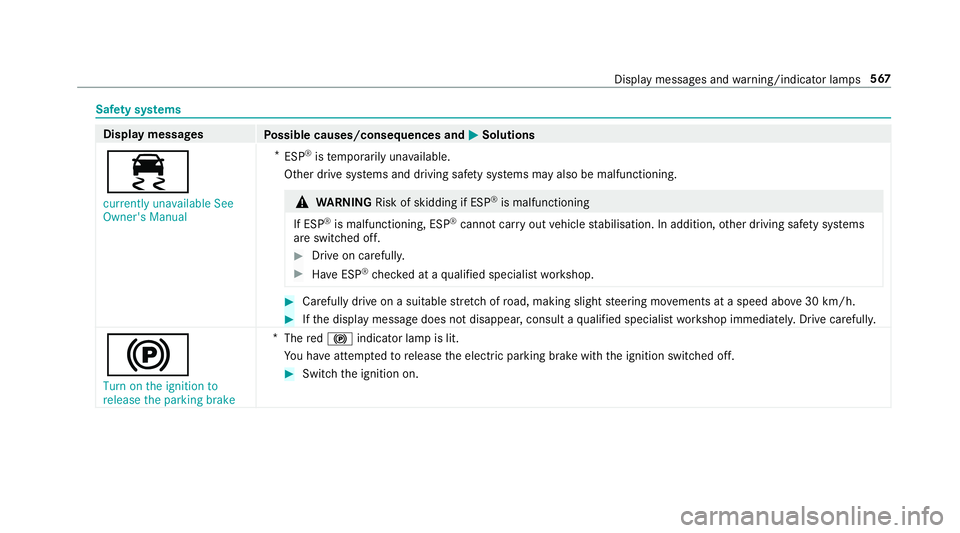
÷ currently unavailable See
Owner's Manual *
ESP ®
is temp orarily una vailable.
Other drive sy stems and driving saf ety sy stems may also be malfunctioning. &
WARNING Risk of skidding if ESP ®
is malfunctioning
If ESP ®
is malfunctioning, ESP ®
cannot car ryout vehicle stabilisation. In addition, other driving saf ety sy stems
are switched off. #
Drive on carefull y. #
Have ESP ®
ch ecked at a qualified specialist workshop. #
Carefully drive on a suitable stre tch of road, making slight steering mo vements at a speed abo ve30 km/h. #
Ifth e display message does not disappear, consult a qualified specialist workshop immediately. Drive carefully.
!
Turn on the ignition to
release the parking brake *
The red! indicator lamp is lit.
Yo u ha veattem ptedto release the electric parking brake with the ignition switched off. #
Switch the ignition on. Display messages and
warning/indicator lamps 567
Page 576 of 681
Display messages
Possible causes/consequences and M
MSolutions #
Have ABS and ESP ®
ch ecked immediately at a qualified specialist workshop. #
Carefully drive on a suitable stre tch of road, making slight steering mo vements at a speed abo ve30 km/h. #
Ifth e display message does not disappear, consult a qualified specialist workshop immediately. Drive carefully.
!
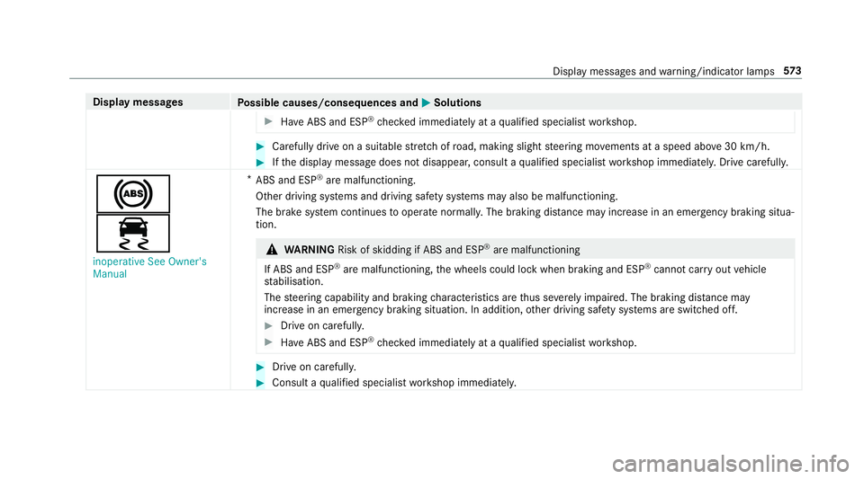
÷
inoperative See Owner's
Manual *
ABS and ESP ®
are malfunctioning.
Other driving sy stems and driving saf ety sy stems may also be malfunctioning.
The brake sy stem continues tooperate normally. The braking dis tance may increase in an emergency braking situa‐
tion. &
WARNING Risk of skidding if ABS and ESP ®
are malfunctioning
If ABS and ESP ®
are malfunctioning, the wheels could lock when braking and ESP ®
cann otcar ryout vehicle
st abilisation.
The steering capability and braking characteristics are thus se verely impaired. The br aking distance may
increase in an emergency braking situation. In addition, other driving saf ety sy stems are switched off. #
Drive on carefull y. #
Have ABS and ESP ®
ch ecked immediately at a qualified specialist workshop. #
Drive on carefully. #
Consult a qualified specialist workshop immediatel y. Displ
aymessa ges and warning/indicator lamps 573
Page 578 of 681
Display messages
Possible causes/consequences and M
MSolutions #
Consult a qualified specialist workshop.
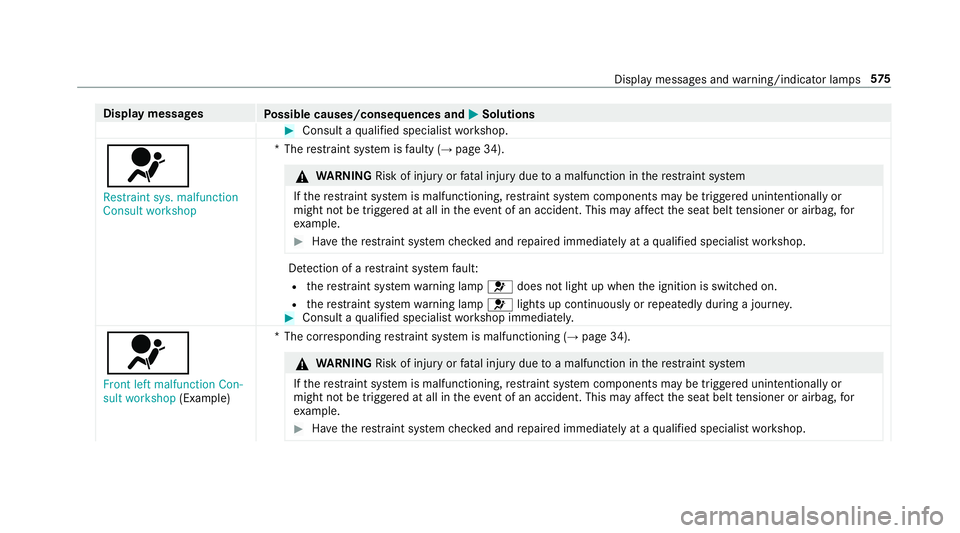
6 Restraint sys. malfunction
Consult workshop *T
herestra int sy stem is faulty (→ page 34). &
WARNING Risk of inju ryor fata l injury due toa malfunction in there stra int sy stem
If th ere stra int sy stem is malfunctioning, restra int sy stem components may be triggered unintentionally or
might not be triggered at all in theeve nt of an accident. This may af fect the seat belt tensioner or airbag, for
ex ample. #
Have there stra int sy stem checked and repaired immediately at a qualified specialist workshop. De
tection of a restra int sy stem fault:
R there stra int sy stem warning lamp 6does not light up when the ignition is switched on.
R there stra int sy stem warning lamp 6lights up continuously or repeatedly during a journe y. #
Consult a qualified specialist workshop immediatel y.
6
Front left malfunction Con-
sult workshop (Example) *T
he cor responding restra int sy stem is malfunctioning (→ page 34). &
WARNING Risk of inju ryor fata l injury due toa malfunction in there stra int sy stem
If th ere stra int sy stem is malfunctioning, restra int sy stem components may be triggered unintentionally or
might not be triggered at all in theev ent of an accident. This may af fect the seat belt tensioner or airbag, for
ex ample. #
Have there stra int sy stem checked and repaired immediately at a qualified specialist workshop. Display messages and
warning/indicator lamps 575
Page 579 of 681
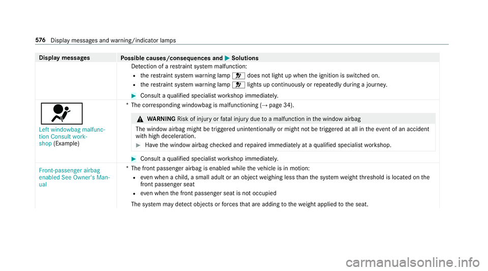
Display messages
Possible causes/consequences and M
MSolutions
De tection of a restra int sy stem malfunction:
R there stra int sy stem warning lamp 6does not light up when the ignition is switched on.
R there stra int sy stem warning lamp 6lights up continuously or repeatedly during a journe y. #
Consult a qualified specialist workshop immediatel y.
6
Left windowbag malfunc-
tion Consult work-
shop (Example) *T
he cor responding windowbag is malfunctioning (→ page 34). &
WARNING Risk of inju ryor fata l injury due toa malfunction in the window airbag
The window airbag might be triggered unintentionally or might not be triggered at all in theeve nt of an accident
wi th high deceleration. #
Have the window airbag checked and repaired immediately at a qualified specialist workshop. #
Consult a qualified specialist workshop immediatel y.
Front-passenger airbag
enabled See Owner's Man-
ual *T
he front passenger airbag is enabled while theve hicle is in motion:
R even when a child, a small adult or an object weighing less than the sy stem weight thre shold is located on the
front passenger seat
R even when the front passenger seat is not occupied
The sy stem may de tect objects or forc es that are adding tothewe ight applied tothe seat. 576
Displaymessa ges and warning/indicator lamps
Page 617 of 681
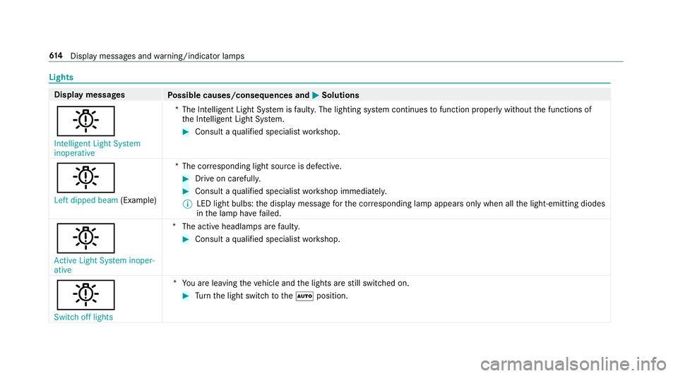
Lights
Display messages
Possible causes/consequences and M
MSolutions
b Intelligent Light System
inoperative *T
he Intelligent Light Sy stem is faulty. The lighting sy stem continues tofunction properly without the functions of
th e Intelligent Light Sy stem. #
Consult a qualified specialist workshop.
b Left dipped beam (Example)*T
he cor responding light source is defective. #
Drive on carefully. #
Consult a qualified specialist workshop immediatel y.
% LED light bulbs: the display message forth e cor responding lamp appears only when allthe light-emitting diodes
in the lamp ha vefailed.
b Active Light System inoper-
ative *T
he active headlamp s arefaulty. #
Consult a qualified specialist workshop.
b Switch off lights *Y
ou are leaving theve hicle and the lights are still switched on. #
Turn the light switch totheà position. 61 4
Displaymessa ges and warning/indicator lamps