length MERCEDES-BENZ GLE SUV 2021 Owners Manual
[x] Cancel search | Manufacturer: MERCEDES-BENZ, Model Year: 2021, Model line: GLE SUV, Model: MERCEDES-BENZ GLE SUV 2021Pages: 545, PDF Size: 9.37 MB
Page 51 of 545
#
Have theve hicle towe dto aqu alified
specialist workshop in order tohave the
deplo yed airbag replaced. Ha
ve deplo yed airbags replaced immediately. St
atus of the front passenger front airbag Fu
nction of the automatic front passenger
airbag shu toff
The automatic front passenger airbag shutoff is
able todetect whe ther the front passenger seat
is occupied bya person or a child restra int sys‐
te m. The front passenger airbag is enabled or
disabled accordingly. &
WARNING Risk of injury or death dueto
objects under the co-driver seat
Objects trapped under the co-driver seat can
inter fere with the function of the automatic
co-driver airbag shutoff or damage the sys‐
te m. #
Do not store any objects under the co-
driver seat. #
When the co-driver seat is occupied,
make sure that no objects are trapped
under the co-driver seat. When
fitting a child restra int sy stem tothe front
passenger seat, alw ays make sure of thefo llow‐
ing:
R Ensure that thech ild restra int sy stem is posi‐
tioned cor rectly (/ page 59).
R Alw ays comply with thech ild restra int sys‐
te m manufacturer's ins tallation instructions.
R Never place objects (e.g. cushions) under or
behind thech ild restra int sy stem.
R Fully retract the seat cushion length adjust‐
ment.
R The entire base of thech ild restra int sy stem
must alw aysre st on the sitting sur face of the
front passenger seat.
R The backrest of thefo rw ard-facing child
re stra int sy stem must, as far as possible, be
re sting on the seat backrest of the front
passenger seat. R
The child restra int sy stem must not touch the
ro of or be put under stra in by the head
re stra ints. Adjust the seat backrest inclina‐
tion and the head restra int setting accord‐
ing ly. &
WARNING Risk of injury or death dueto
objects between the seat sur face and
th ech ild restra int sy stem
Objects between the sitting sur face and the
ch ild restra int sy stem could af fect the func‐
tion of the automatic co-driver airbag shut‐
off. #
Do not place any objects between the
sitting sur face and thech ild restra int
sy stem. #
The entire base of thech ild restra int
sy stem must alw aysre st on the sitting
sur face of the co-driver seat. #
The backrest of thefo rw ard-facing child
re stra int sy stem must, as far as possi‐
ble, be resting on the seat backrest of
th e co-driver seat. 48
Occupant saf ety
Page 54 of 545
Alw
ays ensure that the front passenger air‐
bag is disabled. The PASSENGER AIR BAG
OFF indicator lamp must be lit.
NEVER use a rear wa rd-facing child restra int
sy stem on a seat with an ENABLED FRONT
AIRB AG. This can result in the DEAT H of or
SERIOUS INJU RYtotheCH ILD. When
fitting a child restra int sy stem tothe front
passenger seat, obser vetheve hicle-specific
information (/ page71).
Depending on thech ild restra int sy stem and the
st ature of thech ild, thePA SSENGER AIR BAG
OFF indicator lamp may be off. In this case, do
not fit th ere ar wa rd-facing child restra int sy stem
to the front passenger seat.
Ins tead, fit th ere ar wa rd-facing child restra int
sy stem toa suitable rear seat.
Af terfitting a forw ard-facing child restra int
sy stem tothe front passenger seat: depend‐
ing on thech ild restra int sy stem and thest ature
of thech ild, PASSENGER AIR BAG OFF may be lit
continuously or be off. Alw ays obser vethefo l‐
lowing information. &
WARNING Risk of injury or death dueto
incor rect positioning of thefo rw ard-
fa cing child restra int sy stem
If yo u secure a child in a forw ard-facing child
re stra int sy stem on the front passenger seat
th at is positioned too close tothe cockpit, in
th eev ent of an accident, thech ild could:
R come into con tact with th eve hicle inte‐
ri or if thePA SSENGER AIR BAG OFF indi‐
cator lamp is lit, forex ample
R bestru ck bythe airbag if thePA SSENGER
AIR BAG OFF indicator lamp is off. #
Alw ays mo vethe front passenger seat
as far back as possible and fully retract
th e seat cushion length adjustment.
While doing so, alw ays make sure that
th e shoulder belt stra p is cor rectly
ro uted from the seat belt outlet of the
ve hicle tothe shoulder belt guide on
th ech ild restra int sy stem. The shoulder
belt stra p must be routed forw ards and
down wards from the seat belt outlet. If
necessar y,adjust the seat belt outlet and
the front passenger seat accord‐
ingly. #
Alw ays comply with thech ild restra int
sy stem manufacturer's ins tallation
instructions. When
fitting a child restra int sy stem tothe front
passenger seat, obser vetheve hicle-specific
information (/ page71).
If a person is sitting on the front passenger
seat: PASSENGER AIR BAG OFF may be lit con‐
tinuously or be off, depending on the person's
st ature.
A person on the front passenger seat must
alw ays obser vethefo llowing information:
R Ifth e front passenger seat is occupied byan
adult or a person with a stature cor respond‐
ing tothat of an adult, thePA SSENGER AIR
BA G OFF indicator lamp must be off. This
indicates that the front passenger airbag is
enabled.
If th ePA SSENGER AIR BAG OFF indicator
lamp is lit continuousl y,an adult or person Occupant saf
ety51
Page 75 of 545
passenger airbag must alw
ays be disabled.
This is only the case if thePA SSENGER AIR
BA G OFF indicator lamp is lit continuously
(/ page 50).
R Ifth ePA SSENGER AIR BAG OFF indicator
lamp is off, the front passenger airbag is ena‐
bled. The front passenger airbag may deploy
during an accident.
Securing thech ild restra int sy stem with the
seat belt on the front passenger seat
When fitting a belt-secu redch ild restra int sys‐
te m on the front passenger seat, alw ays obser ve
th efo llowing:
0073 Obser
vethe no tes on rear wa rd-facing and
fo rw ard-facing child restra int sy stems on
th e front passenger seat (/ page71).
0073 Obse
rveth ech ild restra int sy stem manufac‐
turer's ins tallation and operating instruc‐
tions.
0073 Fo
r a child restra int sy stem in the "Univer‐
sal" or "Semi-Universal" categor y,make
sure that the sy stem has been appr ovedfor
th eve hicle seat. Obser
vethe no tes under "Suitability of
seats for attaching belt-secu redch ild
re stra int sy stems" (/ page67).
0073 When using a
forw ard-facing child restra int
sy stem in weight category I: remo vethe
head restra int from there spective seat, if
possible.
Af terth ech ild restra int sy stem has been
re mo ved, replace the head restra ints again
immediately and adjust them cor rectl y.
0073 The backrest of
thefo rw ard-facing child
re stra int sy stem must, as far as possible, be
re sting on the seat backrest of the front
passenger seat.
0073 If
th e head restra int of thech ild seat cannot
be fully extended when it is ins talled in the
ve hicle, this will result in restrictions on the
maximum size setting forch ild restra int sys‐
te ms in weight category II or III.
Contact with thero of when the head
re stra int is fully extended and lo cked in
place will not result in any restrictions on
use. 0073
The
child restra int sy stem must not be put
under stra in between thero of and the seat
cushion and/or be fitted facing the wrong
direction.
0073 The
child restra int sy stem must not be put
under stra in by the head restra int. Adjust
th e head restra ints as appropriate.
0073 Ne
ver place objects (e.g. cushions) under or
behind thech ild restra int sy stem. #
Set the front passenger seat as far back as
possible and mo vethe seat into the highest
position if possible. #
Fully retract the seat cushion length adjust‐
ment. #
Adjust the seat cushion inclination so that
th e front edge of the seat cushion is in the
highest position and there ar edge of the
seat cushion is in the lo west position. #
Set the seat backrest tothe most vertical
position possible. 72
Occupant saf ety
Page 91 of 545
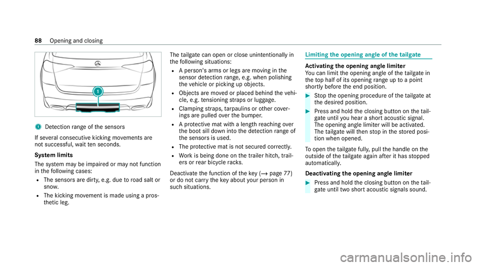
1
Detection range of the sensors
If se veral consecutive kicking mo vements are
not successful, waitte n seconds.
Sy stem limits
The sy stem may be impaired or may not function
in thefo llowing cases:
R The sensors are dirty, e.g. due toroad salt or
sn ow.
R The kicking mo vement is made using a pros‐
th etic leg. The
tailgate can open or close unin tentional lyin
th efo llowing situations:
R A person's arms or legs are moving in the
sensor de tection range, e.g. when polishing
th eve hicle or picking up objects.
R Objects are mo ved or placed behind theve hi‐
cle, e.g. tensioning stra ps or luggage.
R Clamping stra ps, tarp aulins or other co ver‐
ings are pulled overth e bumper.
R A pr otective mat with a length reaching over
th e boot sill down into the de tection range of
th e sensors is used.
R The pr otective mat is not secured cor rectl y.
R Workis being done on the trailer hitch, trail‐
ers or rear bicycle rack s.
Deactivate the function of theke y (/ page77)
or do not car rytheke y about your person in
such situations. Limiting
the opening angle of the tailgate Ac
tivating the opening angle limiter
Yo u can limit the opening angle of theta ilgate in
th eto p half of its opening range up toa point
shortly before the end position. #
Stop the opening procedure of theta ilgate at
th e desired position. #
Press and hold the closing button on theta il‐
ga te until you hear a sho rtacoustic signal.
The opening angle limiter will be activated.
The tailgate will then stop in thestored posi‐
tion when opened.
To open thetai lgate full y,pull the handle on the
outside of theta ilgate again af ter it has stopped
automaticall y.
Deactivating the opening angle limiter #
Press and hold the closing button on theta il‐
ga te until two sho rtacoustic signals sound. 88
Opening and closing
Page 106 of 545
Do not inter
change the head restra ints of the
front and rear seats. Otherwise, you will not be
able toadjust the height and angle of the head
re stra ints cor rectl y.
Ad just the head restra int fore -and-aft position so
th at it is as close as possible tothe back of your
head. &
WARNING Risk of injury or death dueto
incor rect seat position
The seat belt will not of ferth e intended le vel
of pr otection if you ha venot mo vedth e seat
backrest toan almost vertical position.
In particular, you may slip under the seatbelt
and injure yourself. #
Adjust the seat proper lybefore begin‐
ning your journe y. #
Alw ays ensure that the seat backrest is
in an almost vertical position and that
th e shoulder section of your seat belt is
ro uted across the cent reofyour shoul‐
der. &
WARNING Risk of injury duetoexc es‐
sive stra in on the grab handle
If yo u apply your full body weight tothe grab
handle or pull it abruptl y,the grab handle
may be damaged or become loose from its
anchorage. #
Use the grab handles only tostabilise
th e seating position or toassist in get‐
ting in and out of the seat. &
WARNING Risk of injury or death dueto
objects under the co-driver seat
Objects trapped under the co-driver seat can
inter fere with the function of the automatic
co-driver airbag shutoff or damage the sys‐
te m. #
Do not store any objects under the co-
driver seat. #
When the co-driver seat is occupied,
make sure that no objects are trapped
under the co-driver seat. 1
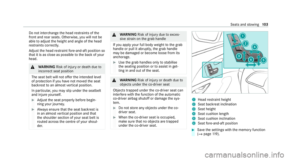
Head restra int height
2 Seat backrest inclination
3 Seat height
4 Seat cushion length
5 Seat cushion inclination
6 Seat fore -and-aft position #
Save the settings with the memory function
(/ page 119). Seats and
stowing 103
Page 223 of 545
R
Sensitive: higher system sensitivity. The
driver is warned earlier and the attention
le ve l de tected byATTENTION ASSIST is adap‐
te d according ly.
If dr owsiness or increasing lapses in concentra‐
tion are de tected, theATTENTION ASSIST: Take
a break! warning appears in the Instrument Dis‐
pla y.Yo u can ackn owledge the message and
ta ke a break where necessar y.Ifyo u do not take
a break and ATTENTION ASSIST continues to
de tect increasing lapses in concentration, you
will be warned again af ter a minimum of
15 minutes. Yo
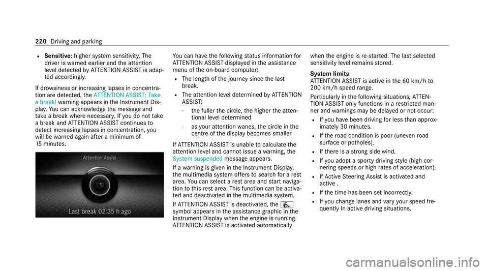
u can ha vethefo llowing status information for
AT TENTION ASSIST displa yed in the assis tance
menu of the on-board computer:
R The length of the journey since the last
break.
R The attention le vel de term ined byATTENTION
ASSIS T:
- the fuller the circle, the higher the atten‐
tional le vel de term ined
- asyour attention wanes, the circle in the
centre of the display becomes smaller
If AT TENTION ASSIST is unable tocalculate the
attention le vel and cannot issue a warning, the
System suspended messageappears.
If a warning is given in the Instrument Displa y,
th e multimedia sy stem of fers to sear chfor a rest
area. You can select a rest area and start naviga‐
tion tothis rest area. This function can be activa‐
te d and deactivated in the multimedia sy stem.
If AT TENTION ASSIST is deactivated, theÛ
symbol appears in the assis tance graphic in the
Instrument Display when the engine is running.
AT TENTION ASSIST is activated automatically when
the engine is re-sta rted. The last selected
sensitivity le velre mains stored.
Sy stem limits
AT TENTION ASSIST is active in the 60 km/h to
200 km/h speed range.
Pa rticularly in thefo llowing situations, ATTEN‐
TION ASSIST only functions in a restricted man‐
ner and warnings may be dela yed or not occur:
R Ifyo u ha vebeen driving for less than appr ox‐
imately 30 minutes.
R Ifth ero ad condition is poor (une venro ad
sur face or po tholes).
R Ifth ere is a strong side wind.
R Ifyo u adopt a sporty driving style (high cor‐
nering speeds or high rates of acceleration).
R IfAc tive Steering Assist is activated and
active .
R Ifth e time has been set incor rectl y.
R Ifyo uch ange lanes and vary your speed fre‐
qu ently In active driving situations. 220
Driving and parking
Page 276 of 545
If a
warning tone also sounds for appro ximately
two seconds everytime theve hicle is star ted, it
may be due toone of thefo llowing causes:
R The sensors are dirty: cleanthe sensors
and obser vethe no tes on care of vehicle
parts (/ page 361).
R Parking Assist PARKTRONIC has been
deactivated due toa malfunction: restart
th eve hicle. If the problem persists, consult a
qu alified specialist workshop.
Fu nction of the passive side impact pr otec‐
tion
Pa ssive side impact pr otection is an additional
Pa rking Assist PARKTRONIC function which
wa rnsth e driver about obs tacles at the side of
th eve hicle. A warning is issued when obs tacles
are de tected between the front and rear de tec‐
tion range. In order for an object on the side to
be de tected, the sensors in the front and rear
bumper must firs t de tect the object while you
are driving past it.
During the parking procedure or manoeuvring,
objects are de tected as theve hicle drives past.
If yo usteer in the direction of a de tected obs ta‐cle and
there is a risk of a lateral collision, a
wa rning is issued and the segments light up in
colour in the displa y.
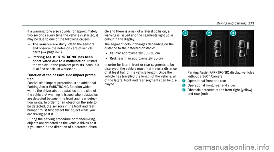
The segment colour changes depending on the
dis tance tothe de tected obs tacle:
R Yello w: appr oximately 30 - 60 cm
R Red:less than appr oximately 30 cm
In order for lateral front or rear segments tobe
displa yed, theve hicle must firs t tr ave l a dis tance
of at least half of theve hicle length. Once the
ve hicle has tr avelled the length of theve hicle, all
of the lateral front and rear segments can be dis‐
pla yed. Pa
rking Assist PARKTRONIC display: vehicles
without a 360° Camera
1 Operational front and rear
2 Operational front, rear and sides
3 Obstacle de tected at the front right (yellow)
and rear (red) Driving and parking
273
Page 286 of 545
Te
aching in Trailer Manoeuvring Assist #
Drive forw ards a short dis tance wi th the car/
trailer combination.
The comple tedte ach-in process is shown in
th e media displa y.
% The maximum articulation angle depends on
the length of the trailer. This is calculated by
th e sy stem bydriving theve hicle forw ards,
including cornering. Before the length of the
trailer has been calculated, the maximum
articulation angle is appr oximately 23°. The
longer the trailer is, the higher the maximum
articulation angle (max. appr oximately 60°). Using
Trailer Manoeuvring Assist #
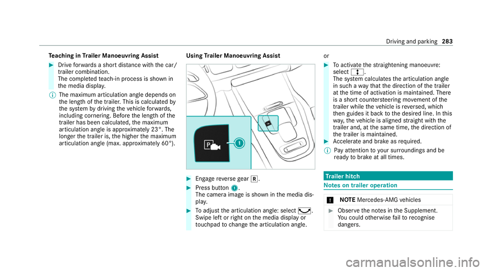
Engage reve rsege ar 005E. #
Press button 1.
The camera image is shown in the media dis‐
pla y. #
Toadjust the articulation angle: select ¸.
Swipe left or right on the media display or
to uchpad tochange the articulation angle. or #
Toactivate thest ra ightening manoeuvre:
select º.
The sy stem calculates the articulation angle
in such a wayth at the direction of the trailer
at the time of activation is maintained. There
is a short counter steering mo vement of the
trailer while theve hicle is reve rsed, which
th en guides it back tothe desired line. In this
wa y,theve hicle is aligned stra ight with the
trailer and, at the same time, the direction of
th e trailer is maintained. #
Accelerate and brake as requ ired.
% Pay attention toyour sur roundings and be
re ady tobrake at all times. Tr
ailer hitch Note
s on trailer operation *
NO
TEMercedes-AMG vehicles #
Obser vethe no tes in the Supplement.
Yo u could otherwise failto recognise
dangers. Driving and park
ing283
Page 323 of 545
particular
the data pr otection regulations, in
yo ur count ry.
Fo rth is reason, before using the dashcam
inform yourself about there gulation de tails
fo rth ere spective countr y.
This function is not permitted in all count ries. #
Obser vethe count ry-specific regula‐
tions. Selecting a USB device
for a video recording
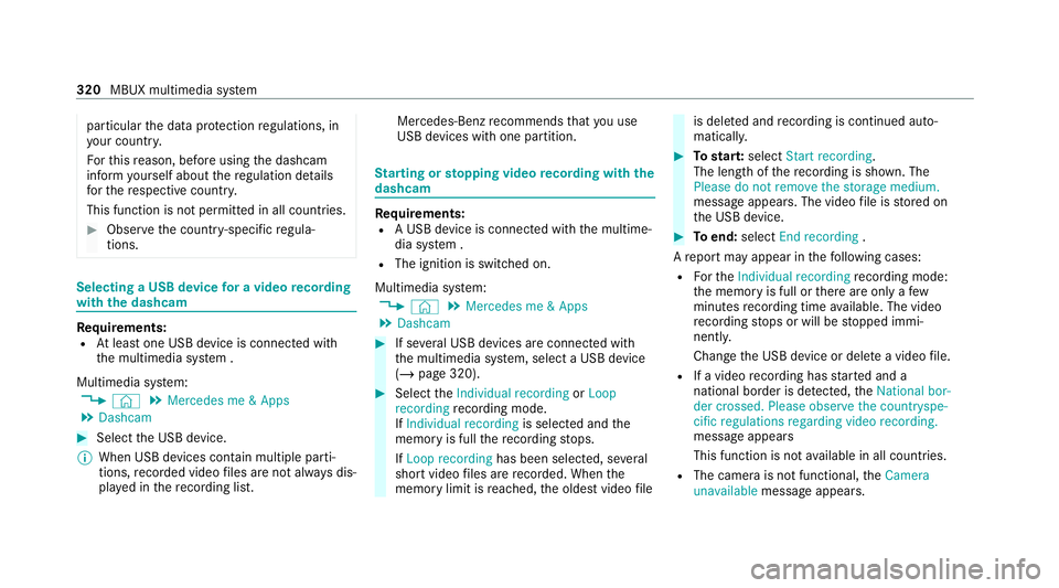
with the dashcam Re
quirements:
R Atleast one USB device is connecte d with
th e multimedia sy stem .
Multimedia sy stem:
4 © 5
Mercedes me & Apps
5 Dashcam #
Select the USB device.
% When USB devices conta in multiple parti‐
tions, recorded video files are not alw ays dis‐
pla yed in there cording list. Mercedes-Benz
recommends that you use
USB devices with one partition. St
arting or stopping video recording with the
da shcam Re
quirements:
R A USB device is connecte d withthe multime‐
dia sy stem .
R The ignition is switched on.
Multimedia sy stem:
4 © 5
Mercedes me & Apps
5 Dashcam #
If se veral USB devices are connec ted with
th e multimedia sy stem, select a USB device
(/ page 320). #
Select theIndividual recording orLoop
recording recording mode.
If Individual recording is selected andthe
memory is full there cording stops.
If Loop recording has been selected, se veral
short video files are recorded. When the
memory limit is reached, the oldest video file is dele
ted and recording is continued auto‐
matical ly. #
Tostar t:select Start recording.
The length of there cording is shown. The
Please do not remove the storage medium.
message appea rs. The video file is stored on
th e USB device. #
Toend: select End recording .
A report may appear in thefo llowing cases:
R Forth eIndividual recording recording mode:
th e memory is full or there are only a few
minutes recording time available. The video
re cording stops or will be stopped immi‐
nently.
Chan gethe USB device or dele tea video file.
R If a video recording has star ted and a
national border is de tected, theNational bor-
der crossed. Please observe the countryspe-
cific regulations regarding video recording.
message appears
This function is not available in all countries.
R The camera is not functional, theCamera
unavailable message appears. 320
MBUX multimedia sy stem
Page 423 of 545
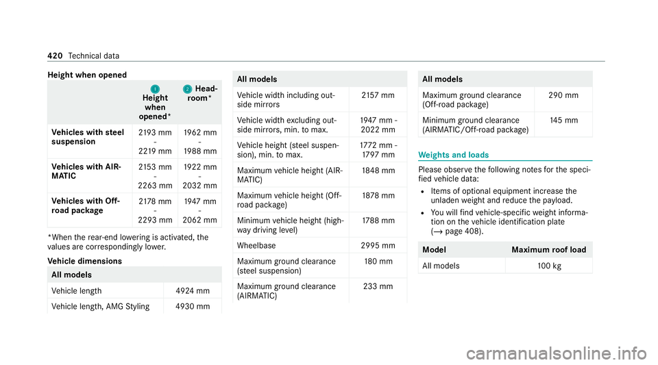
Height when opened
1 1
Height
when
opened* 2 2
Head‐
ro om*
Ve hicles with steel
suspension 21
93 mm
-
22 19 mm 19
62 mm
-
19 88 mm
Ve hicles with AIR‐
MATIC 21
53 mm
-
2263 mm 19
22 mm
-
2032 mm
Ve hicles with Off-
ro ad pac kage 21
78 mm
-
2293 mm 19
47 mm
-
2062 mm *When
there ar-end lo wering is acti vated, the
va lues are cor respondingly lo wer.
Ve hicle dimensions All models
Ve
hicle lengt h4 924 mm
Ve hicle length, AMG Styling 4930 mm All models
Ve
hicle width including out‐
side mir rors 21
57 mm
Ve hicle width excluding out‐
side mir rors, min. tomax. 19
47 mm -
2022 mm
Ve hicle height (s teel suspen‐
sion), min. tomax. 17
72 mm -
17 97 mm
Maximum vehicle height (AIR‐
MATIC) 18
48 mm
Maximum vehicle height (Off-
ro ad pac kage) 18
78 mm
Minimum vehicle height (high‐
wa y driving le vel) 17
88 mm
Wheelbase 2995 mm
Maximum ground cleara nce
(s te el suspension) 18
0 mm
Maximum ground cleara nce
(AIRMATIC) 233 mm All models
Maximum ground clearance
(Off-road pa
ckage) 290 mm
Minimum ground clearance
(AIRMATIC/Off- road pac kage) 14
5 mm We
ights and loads Please obser
vethefo llowing no tesfo rth e speci‐
fi ed vehicle data:
R Items of optional equipment increase the
unladen weight and reduce the pa yload.
R You will find vehicle-specific weight informa‐
tion on theve hicle identification plate
(/ page 408). Model
Maximumroof load
All models 100kg 420
Tech nical da ta