change wheel MERCEDES-BENZ GLK-Class 2014 X204 Owner's Guide
[x] Cancel search | Manufacturer: MERCEDES-BENZ, Model Year: 2014, Model line: GLK-Class, Model: MERCEDES-BENZ GLK-Class 2014 X204Pages: 382, PDF Size: 4.36 MB
Page 339 of 382

recommended tire pressure for your vehicle
when adjusting the tire pressure
(Y page 334). 0043
Example: maximum permissible tire
pressure
i The actual values for tires are vehicle-
specific and may deviate from the values in
the illustration. Checking the tire pressures
Important safety notes Observe the "tire pressure information"
section (Y page 334).
Information on air pressure for the tires on
your vehicle can be found:
R on the vehicle's Tire and Loading
Information placard on the B-pillar
R on the tire pressure label on the fuel filler
flap
R in the "Tire pressure information" section
Checking tire pressures manually To determine and set the correct tire
pressure, proceed as follows:
X Remove the valve cap of the tire that is to
be checked.
X Press the tire pressure gauge securely onto
the valve.
X Read the tire pressure and compare it with
the recommended value on the Tire and
Loading Information placard on the
B-pillar on the driver's side of your vehicle. X
If necessary, increase the tire pressure to
the recommended value (Y page 334).
X If the tire pressure is too high, release air
by pressing down the metal pin in the valve
using the tip of a pen, for example. Then,
check the tire pressure again using the tire
pressure gauge.
X Screw the valve cap onto the valve.
X Repeat these steps for the other tires. Tire pressure loss warning system
(Canada only)
General notes While the vehicle is in motion, the tire
pressure loss warning system monitors the
set tire pressure using the rotational speed of
the wheels. This enables the system to detect
significant pressure loss in a tire. If the speed
of rotation of a wheel changes as a result of
a loss of pressure, a corresponding warning
message will appear in the multifunction
display.
You can recognize the tire pressure loss
warning by the
Run Flat Indicator Run Flat Indicator
Active Press 'OK' to Restart
Active Press 'OK' to Restart message
which appears in the Service
Servicemenu of the
multifunction display. Information on the
message display can be found in the
"Restarting the tire pressure loss warning
system" section (Y page 338).
Important safety notes The tire pressure warning system does not
warn you of an incorrectly set tire pressure.
Observe the notes on the recommended tire
pressure (Y
page 334).
The tire pressure loss warning does not
replace the need to regularly check the tire
pressure. An even loss of pressure on several
tires at the same time cannot be detected by
the tire pressure loss warning system.
The tire pressure monitor is not able to warn
you of a sudden loss of pressure, e.g. if the
tire is penetrated by a foreign object. In the Tire pressure
337Wheels and tires Z
Page 340 of 382
event of a sudden loss of pressure, bring the
vehicle to a halt by braking carefully. Avoid
abrupt steering maneuvers.
The function of the tire pressure loss warning
system is limited or delayed if:
R snow chains are mounted on your vehicle's
tires.
R road conditions are wintry.
R you are driving on sand or gravel.
R you adopt a very sporty driving style
(cornering at high speeds or driving with
high rates of acceleration).
R you are towing a very heavy or large trailer.
R you are driving with a heavy load (in the
vehicle or on the roof).
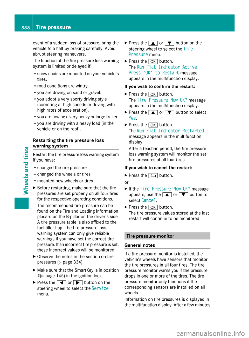
Restarting the tire pressure loss
warning system Restart the tire pressure loss warning system
if you have:
R changed the tire pressure
R changed the wheels or tires
R mounted new wheels or tires
X Before restarting, make sure that the tire
pressures are set properly on all four tires
for the respective operating conditions.
The recommended tire pressure can be
found on the Tire and Loading Information
placard on the B-pillar on the driver's side
A tire pressure table is also affixed to the
fuel filler flap. The tire pressure loss
warning system can only give reliable
warnings if you have set the correct tire
pressure. If an incorrect tire pressure is set,
these incorrect values will be monitored.
X Observe the notes in the section on tire
pressures (Y page 334).
X Make sure that the SmartKey is in position
2(Y page 145) in the ignition lock.
X Press the 0059or0065 button on the
steering wheel to select the Service
Service
menu. X
Press the 0063or0064 button on the
steering wheel to select the Tire Tire
Pressure
Pressure menu.
X Press the 0076button.
The Run Flat Indicator Active
Run Flat Indicator Active
Press 'OK' to Restart
Press 'OK' to Restart message
appears in the multifunction display.
If you wish to confirm the restart:
X Press the 0076button.
The Tire Pressure Now OK? Tire Pressure Now OK? message
appears in the multifunction display.
X Press the 0063or0064 button to select
Yes
Yes.
X Press the 0076button.
The Run Flat Indicator Restarted
Run Flat Indicator Restarted
message appears in the multifunction
display.
After a teach-in period, the tire pressure
loss warning system will monitor the set
tire pressures of all four tires.
If you wish to cancel the restart:
X Press the 0038button.
or
X If the Tire Pressure Now OK? Tire Pressure Now OK? message
appears, use the 0063or0064 button to
select Cancel
Cancel .
X Press the 0076button.
The tire pressure values stored at the last
restart will continue to be monitored. Tire pressure monitor
General notes If a tire pressure monitor is installed, the
vehicle's wheels have sensors that monitor
the tire pressures in all four tires. The tire
pressure monitor warns you if the pressure
drops in one or more of the tires. The tire
pressure monitor only functions if the
corresponding sensors are installed on all
wheels.
Information on tire pressures is displayed in
the multifunction display. After a few minutes338
Tire pressureWheels and tires
Page 343 of 382
Tire pressure monitor warning
messages
If the tire pressure monitor detects a pressure
loss in one or more tires, a warning message
is shown in the multifunction display and the
yellow tire pressure monitor warning lamp
comes on.
R If the Correct Tire Pressure
Correct Tire Pressure message
appears in the multifunction display, the
tire pressure in at least one tire is too low
and must be corrected at the next
opportunity.
R If the Check
Check Tires Tiresmessage appears in the
multifunction display, the tire pressure in
one or more tires has dropped significantly
and the tires must be checked.
R If the Warning Tire Malfunction
Warning Tire Malfunction
appears in the multifunction display, the
tire pressure in one or more tires has
dropped suddenly and the tires must be
checked.
Observe the instructions and safety notes in
the display messages in the "Tires" section
(Y page 256).
i If the wheel positions on the vehicle are
rotated, the tire pressures may be
displayed for the wrong positions for a
short time. This is rectified after a few
minutes of driving, and the tire pressures
are displayed for the correct positions.
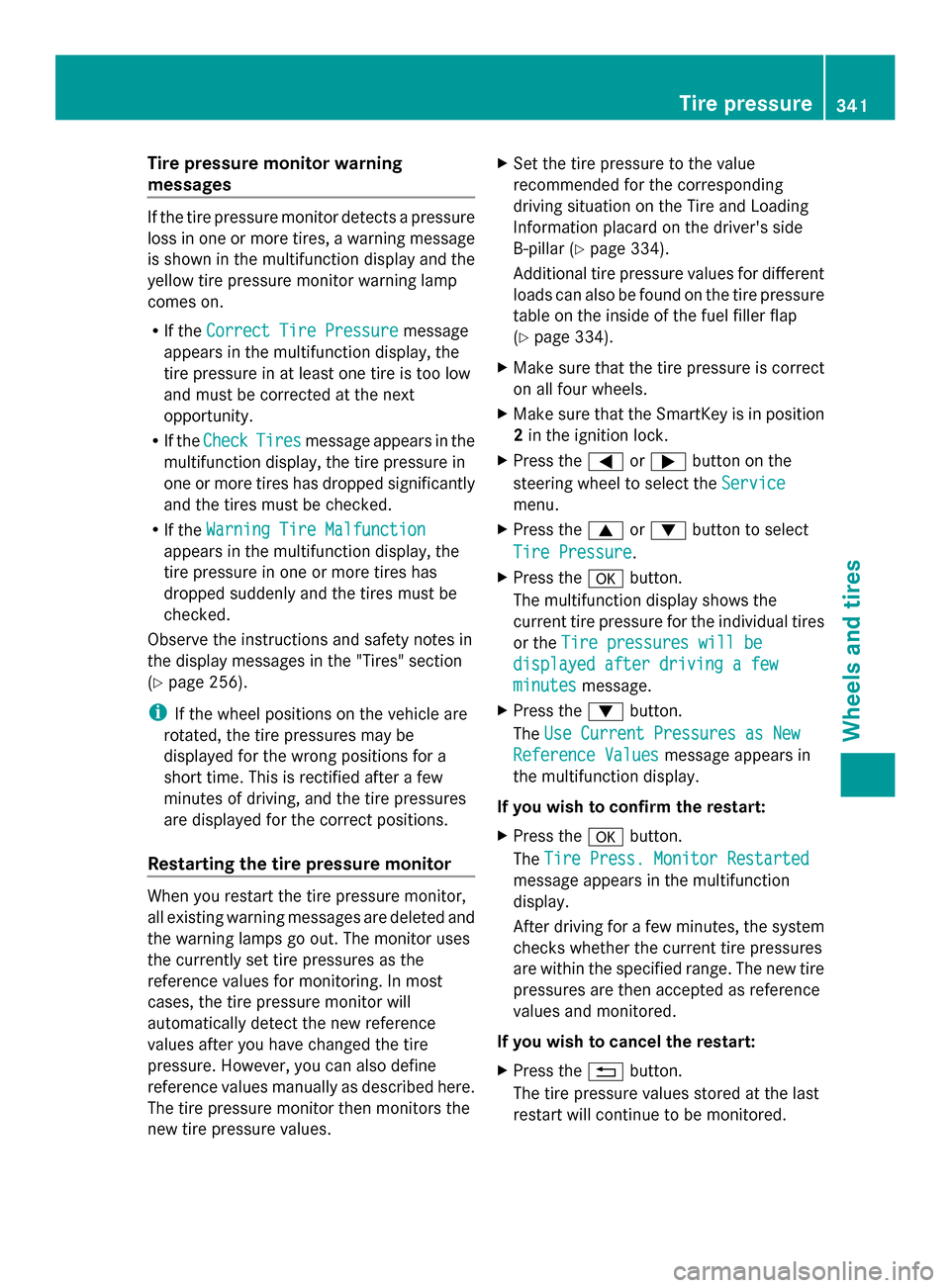
Restarting the tire pressure monitor When you restart the tire pressure monitor,
all existing warning messages are deleted and
the warning lamps go out. The monitor uses
the currently set tire pressures as the
reference values for monitoring. In most
cases, the tire pressure monitor will
automatically detect the new reference
values after you have changed the tire
pressure. However, you can also define
reference values manually as described here.
The tire pressure monitor then monitors the
new tire pressure values. X
Set the tire pressure to the value
recommended for the corresponding
driving situation on the Tire and Loading
Information placard on the driver's side
B-pillar (Y page 334).
Additional tire pressure values for different
loads can also be found on the tire pressure
table on the inside of the fuel filler flap
(Y page 334).
X Make sure that the tire pressure is correct
on all four wheels.
X Make sure that the SmartKey is in position
2in the ignition lock.
X Press the 0059or0065 button on the
steering wheel to select the Service
Service
menu.
X Press the 0063or0064 button to select
Tire Pressure Tire Pressure .
X Press the 0076button.
The multifunction display shows the
current tire pressure for the individual tires
or the Tire pressures will be Tire pressures will be
displayed after driving a few
displayed after driving a few
minutes minutes message.
X Press the 0064button.
The Use Current Pressures as New
Use Current Pressures as New
Reference Values
Reference Values message appears in
the multifunction display.
If you wish to confirm the restart:
X Press the 0076button.
The Tire Press. Monitor Restarted Tire Press. Monitor Restarted
message appears in the multifunction
display.
After driving for a few minutes, the system
checks whether the current tire pressures
are within the specified range. The new tire
pressures are then accepted as reference
values and monitored.
If you wish to cancel the restart:
X Press the 0038button.
The tire pressure values stored at the last
restart will continue to be monitored. Tire pressure
341Wheels and tires Z
Page 356 of 382
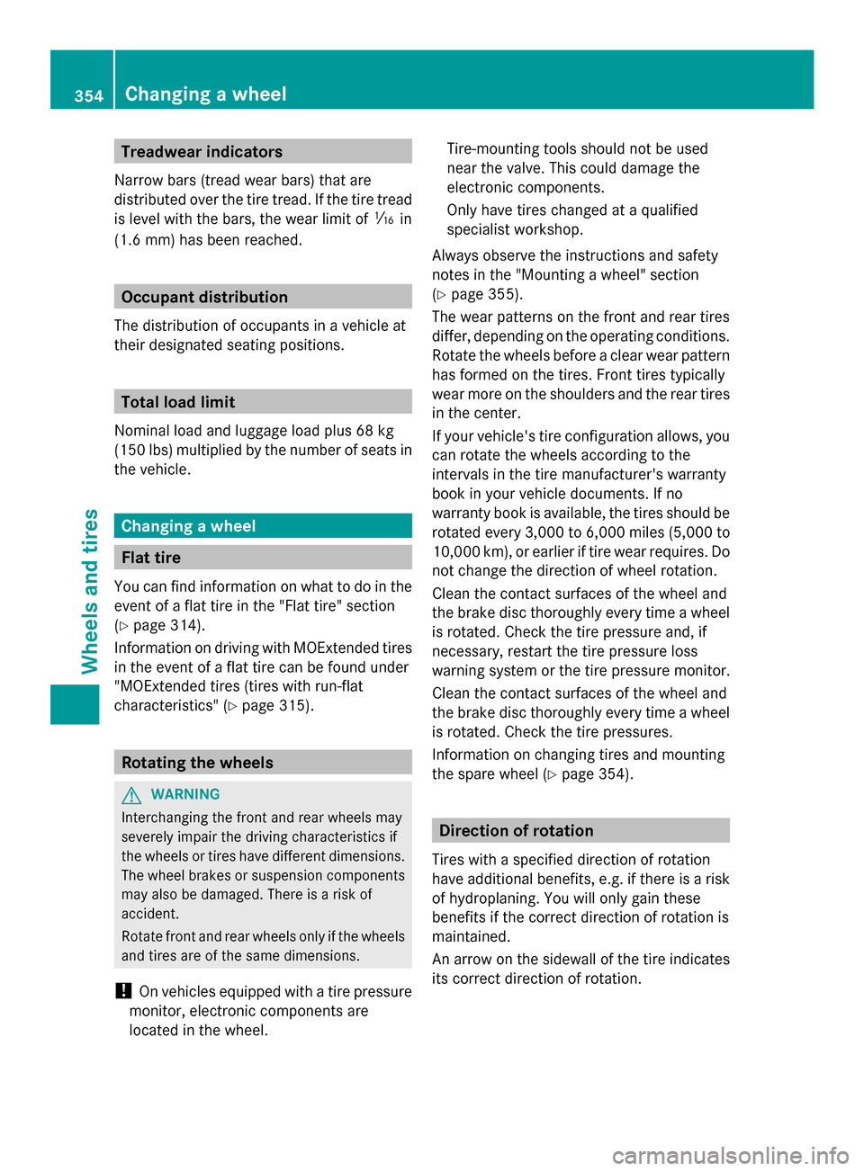
Treadwear indicators
Narrow bars (tread wear bars) that are
distributed over the tire tread. If the tire tread
is level with the bars, the wear limit of 00CDin
(1.6 mm) has been reached. Occupant distribution
The distribution of occupants in a vehicle at
their designated seating positions. Total load limit
Nominal load and luggage load plus 68 kg
(150 lbs) multiplied by the number of seats in
the vehicle. Changing a wheel
Flat tire
You can find information on what to do in the
event of a flat tire in the "Flat tire" section
(Y page 314).
Information on driving with MOExtended tires
in the event of a flat tire can be found under
"MOExtended tires (tires with run-flat
characteristics" (Y page 315).Rotating the wheels
G
WARNING
Interchanging the front and rear wheels may
severely impair the driving characteristics if
the wheels or tires have different dimensions.
The wheel brakes or suspension components
may also be damaged. There is a risk of
accident.
Rotate front and rear wheels only if the wheels
and tires are of the same dimensions.
! On vehicles equipped with a tire pressure
monitor, electronic components are
located in the wheel. Tire-mounting tools should not be used
near the valve. This could damage the
electronic components.
Only have tires changed at a qualified
specialist workshop.
Always observe the instructions and safety
notes in the "Mounting a wheel" section
(Y page 355).
The wear patterns on the front and rear tires
differ, depending on the operating conditions.
Rotate the wheels before a clear wear pattern
has formed on the tires. Front tires typically
wear more on the shoulders and the rear tires
in the center.
If your vehicle's tire configuration allows, you
can rotate the wheels according to the
intervals in the tire manufacturer's warranty
book in your vehicle documents. If no
warranty book is available, the tires should be
rotated every 3,000 to 6,000 miles (5,000 to
10,000 km), or earlier if tire wear requires. Do
not change the direction of wheel rotation.
Clean the contact surfaces of the wheel and
the brake disc thoroughly every time a wheel
is rotated. Check the tire pressure and, if
necessary, restart the tire pressure loss
warning system or the tire pressure monitor.
Clean the contact surfaces of the wheel and
the brake disc thoroughly every time a wheel
is rotated. Check the tire pressures.
Information on changing tires and mounting
the spare wheel (Y page 354). Direction of rotation
Tires with a specified direction of rotation
have additional benefits, e.g. if there is a risk
of hydroplaning. You will only gain these
benefits if the correct direction of rotation is
maintained.
An arrow on the sidewall of the tire indicates
its correct direction of rotation. 354
Changing a wheelWheels and tires
Page 357 of 382

Storing wheels
Store wheels that are not being used in a cool,
dry and preferably dark place. Protect the
tires from oil, grease, gasoline and diesel. Cleaning the wheels
G
WARNING
The water jet from a circular jet nozzle (dirt
blasters) can cause invisible exterior damage
to the tires or chassis components.
Components damaged in this way may fail
unexpectedly. There is a risk of an accident.
Do not use power washers with circular jet
nozzles to clean the vehicle. Have damaged
tires or chassis components replaced
immediately. Mounting a wheel
Preparing the vehicle
X Stop the vehicle on solid, non-slippery and
level ground.
X Apply the parking brake.
X Bring the front wheels into the straight-
ahead position.
X Move the selector lever to position P.
X Switch off the engine.
X Vehicles without KEYLESS-GO: remove
the SmartKey from the ignition lock.
X Vehicles with KEYLESS-GO: open the
driver's door.
The on-board electronics have status 0,
which is the same as the SmartKey having
been removed.
X Vehicles with KEYLESS-GO: remove the
Start/Stop button from the ignition lock
(Y page 145).
X If included in the vehicle equipment,
remove the tire-change tool kit from the
vehicle. X
Secure the vehicle to prevent it from rolling
away. Securing the vehicle to prevent it
from rolling away
If your vehicle is equipped with a wheel chock,
it can be found in the tire-change tool kit
(Y
page 314).
The folding wheel chock is an additional
safety measure to prevent the vehicle from
rolling away, for example when changing a
wheel.
X Fold both plates upwards 0043.
X Fold out lower plate 0044.
X Guide the lugs on the lower plate fully into
the openings in base plate 0087. Securing the vehicle on level ground
X
On level ground: place chocks or other
suitable items under the front and rear of
the wheel that is diagonally opposite the
wheel you wish to change. Mounting a wheel
355Wheels and tires Z
Page 358 of 382

Securing the vehicle on slight downhill gradients
X On light downhill gradients: place
chocks or other suitable items in front of
the wheels of the front and rear axle. Raising the vehicle
G
WARNING
If you do not position the jack correctly at the
appropriate jacking point of the vehicle, the
jack could tip over with the vehicle raised.
There is a risk of injury.
Only position the jack at the appropriate
jacking point of the vehicle. The base of the
jack must be positioned vertically, directly
under the jacking point of the vehicle.
The following must be observed when raising
the vehicle:
R to raise the vehicle, only use the vehicle-
specific jack that has been tested and
approved by Mercedes-Benz. If used
incorrectly, the jack could tip over with the
vehicle raised.
R the jack is designed only to raise and hold
the vehicle for a short time while a wheel
is being changed. It is not suited for
performing maintenance work under the
vehicle.
R avoid changing the wheel on uphill and
downhill slopes.
R before raising the vehicle, secure it from
rolling away by applying the parking brake
and inserting wheel chocks. Never disengage the parking brake while the
vehicle is raised.
R the jack must be placed on a firm, flat and
non-slip surface. On a loose surface, a
large, load-bearing underlay must be used.
On a slippery surface, a non-slip underlay
must be used, e.g. rubber mats.
R do not use wooden blocks or similar
objects as a jack underlay. Otherwise, the
jack will not be able to achieve its load-
bearing capacity due to the restricted
height.
R make sure that the distance between the
underside of the tires and the ground does
not exceed 1.2 inche s (3cm).
R never place your hands and feet under the
raised vehicle.
R never lie under the raised vehicle.
R never start the engine when the vehicle is
raised.
R never open or close a door or the tailgate
when the vehicle is raised.
R make sure that no persons are present in
the vehicle when the vehicle is raised.
! The jack is designed exclusively for
jacking up the vehicle at the jacking points.
Otherwise, your vehicle could be damaged. 356
Mounting a wheelWheels and tires
Page 359 of 382

X
Using lug wrench 0043, loosen the bolts on
the wheel you wish to change by about one
full turn. Do not unscrew the bolts
completely. The jacking points are located just behind the
wheel housings of the front wheels and just
in front of the wheel housings of the rear
wheels (arrows).
X Take the ratchet wrench out of the vehicle
tool kit and place it on the hexagon nut of
the jack so that the letters AUFare visible. X
Position jack 0087at jacking point 0044. X
Turn ratchet wrench 0085until jack 0087sits
completely on jacking point 0044and the
base of the jack lies evenly on the ground.
X Turn ratchet wrench 0085until the tire is
raised a maximum of 1.2 in (3 cm) from the
ground. Removing a wheel
! Do not place wheel bolts in sand or on a
dirty surface. The bolt and wheel hub
threads could otherwise be damaged when
you screw them in.
X Unscrew the wheel bolts.
X Remove the wheel. Mounting a new wheel
G
WARNING
Oiled or greased wheel bolts or damaged
wheel bolts/hub threads can cause the wheel Mounting a wheel
357Wheels and tires
Z
Page 360 of 382

bolts to come loose. As a result, you could
lose a wheel while driving. There is a risk of
accident.
Never oil or grease wheel bolts. In the event
of damage to the threads, contact a qualified
specialist workshop immediately. Have the
damaged wheel bolts or hub threads
replaced/renewed. Do not continue driving. G
WARNING
If you tighten the wheel bolts or wheel nuts
when the vehicle is raised, the jack could tip
over. There is a risk of injury.
Only tighten the wheel bolts or wheel nuts
when the vehicle is on the ground.
Always pay attention to the instructions and
safety notes in the "Changing a wheel"
section (Y page 354).
Only use wheel bolts that have been designed
for the wheel and the vehicle. For safety
reasons, Mercedes-Benz recommends that
you only use wheel bolts which have been
approved for Mercedes-Benz vehicles and the
respective wheel. 0043
Wheel bolts for all wheels supplied by the
factory
0044 Wheel bolts for the collapsible spare
wheel
! Always use wheel bolts 0044to mount the
collapsible spare wheel. Using other wheel
bolts to mount the collapsible spare wheel
could damage the brake system. Be sure to use the original-length wheel bolts
when re-mounting the original wheel after it
has been repaired.
!
To prevent damage to the paintwork, hold
the wheel securely against the wheel hub
while screwing in the first wheel bolt. X
Clean the wheel and wheel hub contact
surfaces.
X Place the new wheel on the wheel hub and
push it on.
X Tighten the wheel bolts until they are
finger-tight.
X Inflate the collapsible spare wheel
(Y page 362).
Only then lower the vehicle. Lowering the vehicle
G
WARNING
The wheels could work loose if the wheel nuts
and bolts are not tightened to the specified
tightening torque. There is a risk of accident.
Have the tightening torque immediately
checked at a qualified specialist workshop
after a wheel is changed.
! Inflate the collapsible spare wheel using
the tire inflation compressor before
lowering the vehicle. The wheel rim could
otherwise be damaged. 358
Mounting a wheelWheels and tires
Page 361 of 382

X
Place the ratchet wrench onto the hexagon
nut of the jack so that the letters ABare
visible.
X Turn the ratchet wrench until the vehicle is
once again standing firmly on the ground.
X Place the jack to one side.
X Tighten the wheel bolts evenly in a
crosswise pattern in the sequence
indicated ( 0043to0083). The tightening torque
must be 110 lb-ft (150 Nm).
X Turn the jack back to its initial position and
store it together with the rest of the tire-
change tool kit in the cargo compartment.
X Transport the faulty wheel in the cargo
compartment.
X Check the tire pressure of the newly
mounted wheel and adjust it if necessary.
Observe the recommended tire pressure
(Y page 334).
For further information on stowing the
collapsible spare wheel, see (Y page 363).
i Vehicles with tire pressure monitor: all
wheels mounted must be equipped with
functioning sensors. Wheel and tire combinations
General notes
! For safety reasons, Mercedes-Benz
recommends that you only use tires and
wheels which have been approved by
Mercedes-Benz specifically for your
vehicle. These tires have been specially adapted for
use with the control systems, such as ABS
or ESP
®
, and are marked as follows:
R MO = Mercedes-Benz Original
R MOE = Mercedes-Benz Original Extended
(tires featuring run-flat characteristics)
R MO1 = Mercedes-Benz Original (only
certain AMG tires)
Mercedes-Benz Original Extended tires
may only be used on wheels that have been
specifically approved by Mercedes-Benz.
Only use tires, wheels or accessories
tested and approved by Mercedes-Benz.
Certain characteristics, e.g. handling,
vehicle noise emissions or fuel
consumption, may otherwise be adversely
affected. In addition, when driving with a
load, tire dimension variations could cause
the tires to come into contact with the
bodywork and axle components. This could
result in damage to the tires or the vehicle.
Mercedes-Benz accepts no liability for
damage resulting from the use of tires,
wheels or accessories other than those
tested and approved.
Information on tires, wheels and approved
combinations can be obtained from any
qualified specialist workshop.
! Retreaded tires are neither tested nor
recommended by Mercedes-Benz, since
previous damage cannot always be
detected on retreaded tires. As a result,
Mercedes-Benz cannot guarantee vehicle
safety if retreaded tires are mounted. Do
not mount used tires if you have no
information about their previous usage.
i The recommended pressures for various
operating conditions can be found:
R on the Tire and Loading Information
placard with the recommended tire
pressures on the B-pillar on the driver's
side
R in the tire pressure table on the inside of
the fuel filler flap Wheel and tire combinations
359Wheels and tires Z
Page 378 of 382

Approach/departure angle
Front approach/departure angle
0043is a
maximum of 22.5° and rear approach/
departure angle 0044is a maximum of 24.3 °.
For further information about approach/
departure angles, see ( Ypage 173). Maximum gradient-climbing
capability
Note that the vehicle's gradient-climbing
capability depends on the off-road conditions
and the road surface conditions.
The maximum gradient climbing capability is
70%.
i If the load on the front axle is reduced
when pulling away on a steep uphill slope,
the front wheels have a tendency to spin.
4ETS recognizes this and brakes the
wheels accordingly. The rear wheel torque
is increased, making it easier to drive off.
For further information about the maximum
gradient climbing ability, see (Y page 173).Trailer tow hitch
Mounting dimensions
! If you have a trailer tow hitch retrofitted,
changes to the engine cooling system and
drive train may be necessary, depending on
the vehicle type. Anchorage points for the trailer tow hitch
(example)
0043
Anchorage points
0044 Rear axle center line Trailer loads
Missing values were not available at time of
going to print. All models
Permissible trailer load,
unbraked
Permissible trailer load,
braked
21 3500 lbs
(1588 kg) Maximum drawbar
noseweight
22 280 lbs
(127 kg) Permissible rear axle
load when towing a trailer
3108 lbs
(1410 kg) The actual noseweight may not be higher than
the value which is given. The value can be
found on the trailer tow hitch or trailer
21 At a minimum gradient-climbing capability of 12% from a standstill.
22 The drawbar noseweight is not included in the trailer load. 376
Trailer tow hitchTechnical data