wheel MERCEDES-BENZ GLK-Class 2015 X204 Owner's Manual
[x] Cancel search | Manufacturer: MERCEDES-BENZ, Model Year: 2015, Model line: GLK-Class, Model: MERCEDES-BENZ GLK-Class 2015 X204Pages: 386, PDF Size: 7.16 MB
Page 359 of 386
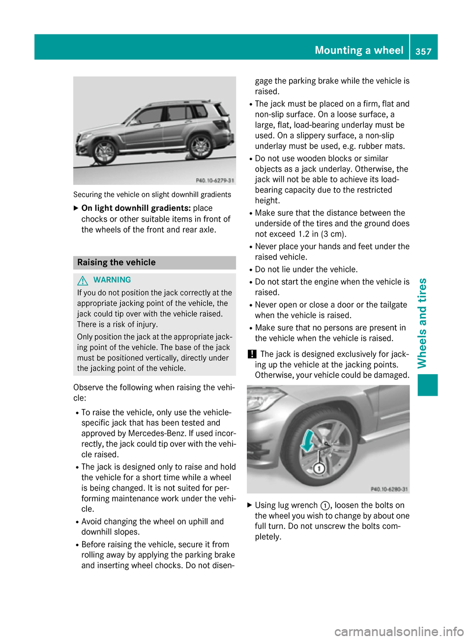
Securing the vehicle on slight downhill gradients
X On light downhill gradients: place
chocks or other suitable items in front of
the wheels of the front and rear axle. Raising the vehicle
G
WARNING
If you do not position the jack correctly at the appropriate jacking point of the vehicle, the
jack could tip over with the vehicle raised.
There is a risk of injury.
Only position the jack at the appropriate jack-
ing point of the vehicle. The base of the jack
must be positioned vertically, directly under
the jacking point of the vehicle.
Observe the following when raising the vehi-
cle:
R To raise the vehicle, only use the vehicle-
specific jack that has been tested and
approved by Mercedes-Benz. If used incor- rectly, the jack could tip over with the vehi-
cle raised.
R The jack is designed only to raise and hold
the vehicle for a short time while a wheel
is being changed. It is not suited for per-
forming maintenance work under the vehi-
cle.
R Avoid changing the wheel on uphill and
downhill slopes.
R Before raising the vehicle, secure it from
rolling away by applying the parking brake
and inserting wheel chocks. Do not disen- gage the parking brake while the vehicle is
raised.
R The jack must be placed on a firm, flat and
non-slip surface. On a loose surface, a
large, flat, load-bearing underlay must be
used. On a slippery surface, a non-slip
underlay must be used, e.g. rubber mats.
R Do not use wooden blocks or similar
objects as a jack underlay. Otherwise, the
jack will not be able to achieve its load-
bearing capacity due to the restricted
height.
R Make sure that the distance between the
underside of the tires and the ground does
not exceed 1.2 in (3 cm).
R Never place your hands and feet under the
raised vehicle.
R Do not lie under the vehicle.
R Do not start the engine when the vehicle is
raised.
R Never open or close a door or the tailgate
when the vehicle is raised.
R Make sure that no persons are present in
the vehicle when the vehicle is raised.
! The jack is designed exclusively for jack-
ing up the vehicle at the jacking points.
Otherwise, your vehicle could be damaged. X
Using lug wrench 0043, loosen the bolts on
the wheel you wish to change by about one full turn. Do not unscrew the bolts com-
pletely. Mounting a wheel
357Wheels and tires Z
Page 360 of 386
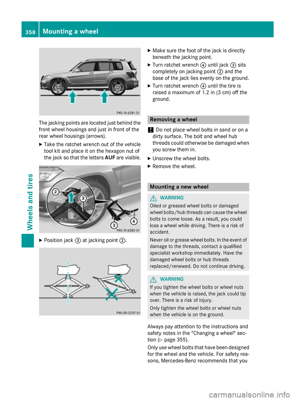
The jacking points are located just behind the
front wheel housings and just in front of the
rear wheel housings (arrows).
X Take the ratchet wrench out of the vehicle
tool kit and place it on the hexagon nut of
the jack so that the letters AUFare visible. X
Position jack 0087at jacking point 0044. X
Make sure the foot of the jack is directly
beneath the jacking point.
X Turn ratchet wrench 0085until jack 0087sits
completely on jacking point 0044and the
base of the jack lies evenly on the ground.
X Turn ratchet wrench 0085until the tire is
raised a maximum of 1.2 in (3 cm) off the
ground. Removing a wheel
! Do not place wheel bolts in sand or on a
dirty surface. The bolt and wheel hub
threads could otherwise be damaged when you screw them in.
X Unscrew the wheel bolts.
X Remove the wheel. Mounting a new wheel
G
WARNING
Oiled or greased wheel bolts or damaged
wheel bolts/hub threads can cause the wheel bolts to come loose. As a result, you could
lose a wheel while driving. There is a risk of
accident.
Never oil or grease wheel bolts. In the event ofdamage to the threads, contact a qualified
specialist workshop immediately. Have the
damaged wheel bolts or hub threads
replaced/renewed. Do not continue driving. G
WARNING
If you tighten the wheel bolts or wheel nuts
when the vehicle is raised, the jack could tip
over. There is a risk of injury.
Only tighten the wheel bolts or wheel nuts
when the vehicle is on the ground.
Always pay attention to the instructions and
safety notes in the "Changing a wheel" sec-
tion (Y page 355).
Only use wheel bolts that have been designed for the wheel and the vehicle. For safety rea-
sons, Mercedes-Benz recommends that you 358
Mounting a wheelWheels and tires
Page 361 of 386
only use wheel bolts which have been
approved for Mercedes-Benz vehicles and the
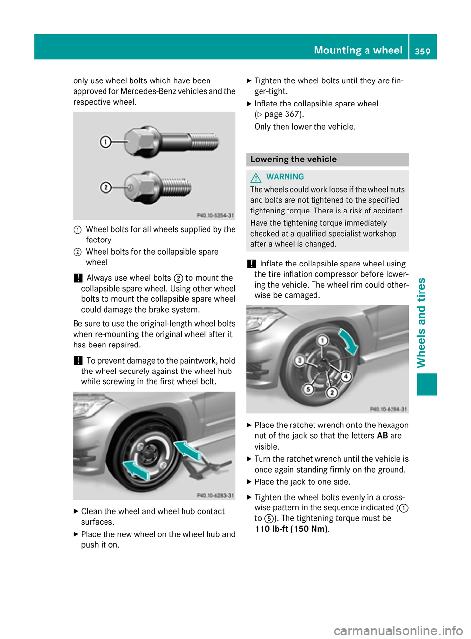
respective wheel. 0043
Wheel bolts for all wheels supplied by the
factory
0044 Wheel bolts for the collapsible spare
wheel
! Always use wheel bolts
0044to mount the
collapsible spare wheel. Using other wheel
bolts to mount the collapsible spare wheel could damage the brake system.
Be sure to use the original-length wheel bolts
when re-mounting the original wheel after it
has been repaired.
! To prevent damage to the paintwork, hold
the wheel securely against the wheel hub
while screwing in the first wheel bolt. X
Clean the wheel and wheel hub contact
surfaces.
X Place the new wheel on the wheel hub and
push it on. X
Tighten the wheel bolts until they are fin-
ger-tight.
X Inflate the collapsible spare wheel
(Y page 367).
Only then lower the vehicle. Lowering the vehicle
G
WARNING
The wheels could work loose if the wheel nuts and bolts are not tightened to the specified
tightening torque. There is a risk of accident.
Have the tightening torque immediately
checked at a qualified specialist workshop
after a wheel is changed.
! Inflate the collapsible spare wheel using
the tire inflation compressor before lower-
ing the vehicle. The wheel rim could other-
wise be damaged. X
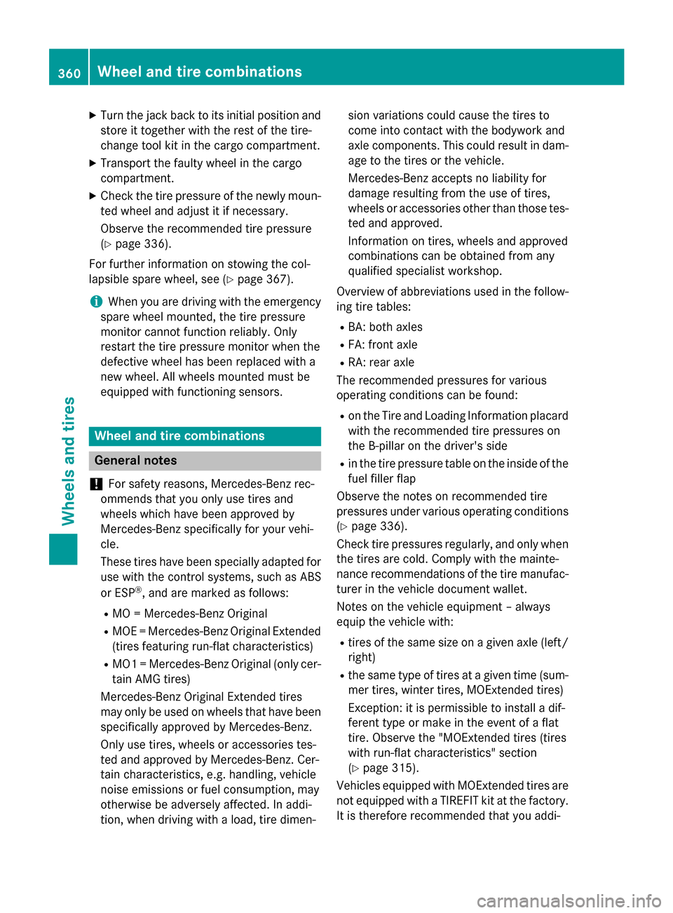
Place the ratchet wrench onto the hexagon
nut of the jack so that the letters ABare
visible.
X Turn the ratchet wrench until the vehicle is
once again standing firmly on the ground.
X Place the jack to one side.
X Tighten the wheel bolts evenly in a cross-
wise pattern in the sequence indicated ( 0043
to 0083). The tightening torque must be
110 lb-ft (150 Nm). Mounting a wheel
359Wheels and tires Z
Page 362 of 386
X
Turn the jack back to its initial position and
store it together with the rest of the tire-
change tool kit in the cargo compartment.
X Transport the faulty wheel in the cargo
compartment.
X Check the tire pressure of the newly moun-
ted wheel and adjust it if necessary.
Observe the recommended tire pressure
(Y page 336).
For further information on stowing the col-
lapsible spare wheel, see (Y page 367).
i When you are driving with the emergency
spare wheel mounted, the tire pressure
monitor cannot function reliably. Only
restart the tire pressure monitor when the
defective wheel has been replaced with a
new wheel. All wheels mounted must be
equipped with functioning sensors. Wheel and tire combinations
General notes
! For safety reasons, Mercedes-Benz rec-
ommends that you only use tires and
wheels which have been approved by
Mercedes-Benz specifically for your vehi-
cle.
These tires have been specially adapted for use with the control systems, such as ABS
or ESP ®
, and are marked as follows:
R MO = Mercedes-Benz Original
R MOE = Mercedes-Benz Original Extended
(tires featuring run-flat characteristics)
R MO1 = Mercedes-Benz Original (only cer-
tain AMG tires)
Mercedes-Benz Original Extended tires
may only be used on wheels that have been
specifically approved by Mercedes-Benz.
Only use tires, wheels or accessories tes-
ted and approved by Mercedes-Benz. Cer-
tain characteristics, e.g. handling, vehicle
noise emissions or fuel consumption, may
otherwise be adversely affected. In addi-
tion, when driving with a load, tire dimen- sion variations could cause the tires to
come into contact with the bodywork and
axle components. This could result in dam-
age to the tires or the vehicle.
Mercedes-Benz accepts no liability for
damage resulting from the use of tires,
wheels or accessories other than those tes-
ted and approved.
Information on tires, wheels and approved
combinations can be obtained from any
qualified specialist workshop.
Overview of abbreviations used in the follow- ing tire tables:
R BA: both axles
R FA: front axle
R RA: rear axle
The recommended pressures for various
operating conditions can be found:
R on the Tire and Loading Information placard
with the recommended tire pressures on
the B-pillar on the driver's side
R in the tire pressure table on the inside of the
fuel filler flap
Observe the notes on recommended tire
pressures under various operating conditions (Y page 336).
Check tire pressures regularly, and only when the tires are cold. Comply with the mainte-
nance recommendations of the tire manufac-
turer in the vehicle document wallet.
Notes on the vehicle equipment – always
equip the vehicle with:
R tires of the same size on a given axle (left/
right)
R the same type of tires at a given time (sum-
mer tires, winter tires, MOExtended tires)
Exception: it is permissible to install a dif-
ferent type or make in the event of a flat
tire. Observe the "MOExtended tires (tires
with run-flat characteristics" section
(Y page 315).
Vehicles equipped with MOExtended tires are
not equipped with a TIREFIT kit at the factory.
It is therefore recommended that you addi- 360
Wheel and tire combinationsWheels and tires
Page 363 of 386
tionally equip your vehicle with a TIREFIT kit if
you mount tires that do not feature run-flat
properties, e.g. winter tires. A TIREFIT kit may be obtained from a qualified specialist work-
shop.
i Not all wheel and tire combinations are
available at the factory for all countries.
i The following pages contain information
on approved wheel rims and tire sizes for
equipping your vehicle with winter tires.
Winter tires are not available at the factory
as standard equipment or optional extras.
If you want to equip your vehicle with
approved winter tires, it may be necessary
to obtain wheel rims in the corresponding
size. The size of the approved winter tires
may differ from the standard tires. This is
dependent on the model and the equip-
ment installed at the factory.
The tires and wheel rims, as well as further information, can be obtained at a qualified
specialist workshop. Wheel and tire combinations
361Wheels and tires Z
Page 364 of 386
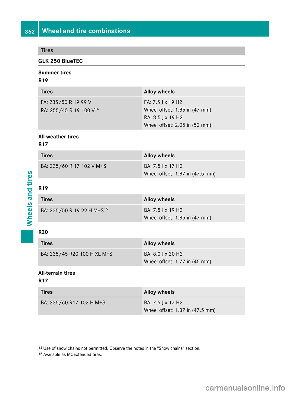
Tires
GLK 250 BlueTEC Summer tires
R19 Tires Alloy wheels
FA: 235/5
0 R 19 99 V
RA : 255/45 R 19 100 V 14 FA: 7.5 J x 19 H2
Wheel offset: 1.85 in (47 mm)
RA: 8.5 J x 19 H2
Wheel offset: 2.05 in (52 mm) All-weather tires
R17 Tires Alloy wheels
BA: 235/60 R 17 102 V M+S BA: 7.5 J x 17 H2
Wheel offset: 1.87 in (47.5 mm) R19
Tires Alloy wheels
BA: 235/50 R 19 99 H M+S
15 BA: 7.5 J x 19 H2
Wheel offset: 1.85 in (47 mm) R20
Tires Alloy wheels
BA: 235/45 R20 100 H XL M+S BA: 8.0 J x 20 H2
Wheel offset: 1.77 in (45 mm) All-terrain tires
R17 Tires Alloy wheels
BA: 235/60 R17 102 H M+S BA: 7.5 J x 17 H2
Wheel offset: 1.87 in (47.5 mm) 14
Use of snow chains not permitted. Observe the notes in the "Snow chains" section.
15 Available as MOExtended tires. 362
Wheel and tire combinationsWheels and tires
Page 365 of 386
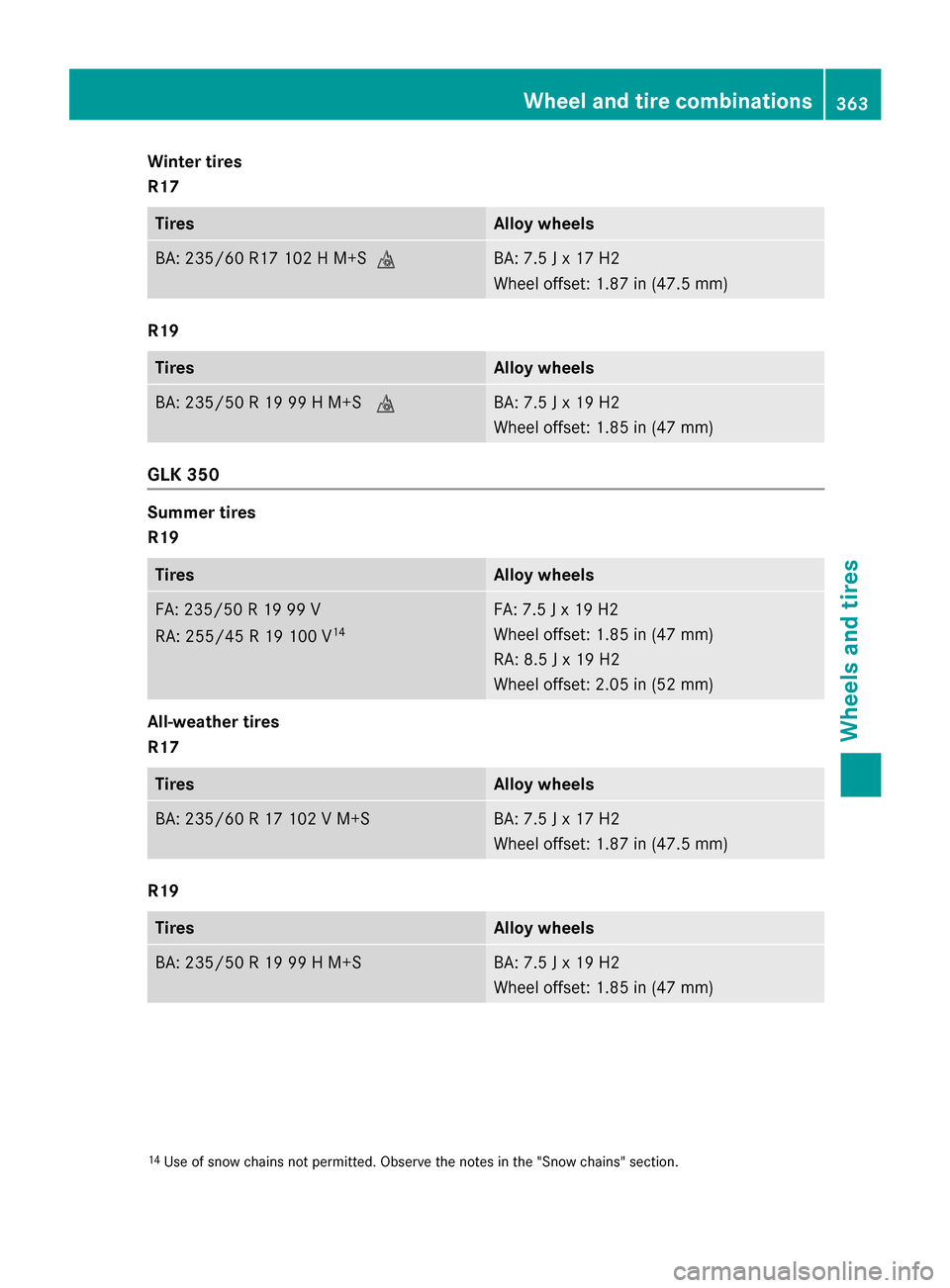
Winter tires
R17
Tires Alloy wheels
BA: 235/60 R17 102 H M+S004D BA: 7.5 J x 17 H2
Wheel offset: 1.87 in (47.5 mm)
R19
Tires Alloy wheels
BA: 235/50 R 19 99 H M+S
004D BA: 7.5 J x 19 H2
Wheel offset: 1.85 in (47 mm)
GLK 350
Summer tires
R19
Tires Alloy wheels
FA: 235/50 R 19 99 V
RA: 255/45 R 19 100 V
14 FA: 7.5 J x 19 H2
Wheel offset: 1.85 in (47 mm)
RA: 8.5 J x 19 H2
Wheel offset: 2.05 in (52 mm)
All-weather tires
R17
Tires Alloy wheels
BA: 235/60 R 17 102 V M+S BA: 7.5 J x 17 H2
Wheel offset: 1.87 in (47.5 mm)
R19
Tires Alloy wheels
BA: 235/50 R 19 99 H M+S BA: 7.5 J x 19 H2
Wheel offset: 1.85 in (47 mm)
14
Use of snow chains not permitted. Observe the notes in the "Snow chains" section. Wheel and tire combinations
363Wheels and tires Z
Page 366 of 386
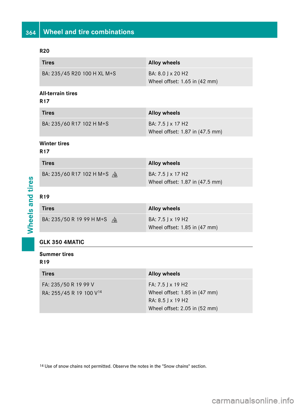
R20
Tires Alloy wheels
BA: 235/45 R20 100 H XL M+S BA: 8.0 J x 20 H2
Wheel offset: 1.65 in (42 mm) All-terrain tires
R17 Tires Alloy wheels
BA: 235/60 R17 102 H M+S BA: 7.5 J x 17 H2
Wheel offset: 1.87 in (47.5 mm) Winter tires
R17
Tires Alloy wheels
BA: 235/60 R17 102 H M+S
004D BA: 7.5 J x 17 H2
Wheel offset: 1.87 in (47.5 mm) R19
Tires Alloy wheels
BA: 235/50 R 19 99 H M+S
004D BA: 7.5 J x 19 H2
Wheel offset: 1.85 in (47 mm) GLK 350 4MATIC
Summer tires
R19
Tires Alloy wheels
FA: 235/50 R 19 99 V
RA: 255/45 R 19 100 V
14 FA: 7.5 J x 19 H2
Wheel offset: 1.85 in (47 mm)
RA: 8.5 J x 19 H2
Wheel offset: 2.05 in (52 mm) 14
Use of snow chains not permitted. Observe the notes in the "Snow chains" section. 364
Wheel and tire combinationsWheels and tires
Page 367 of 386
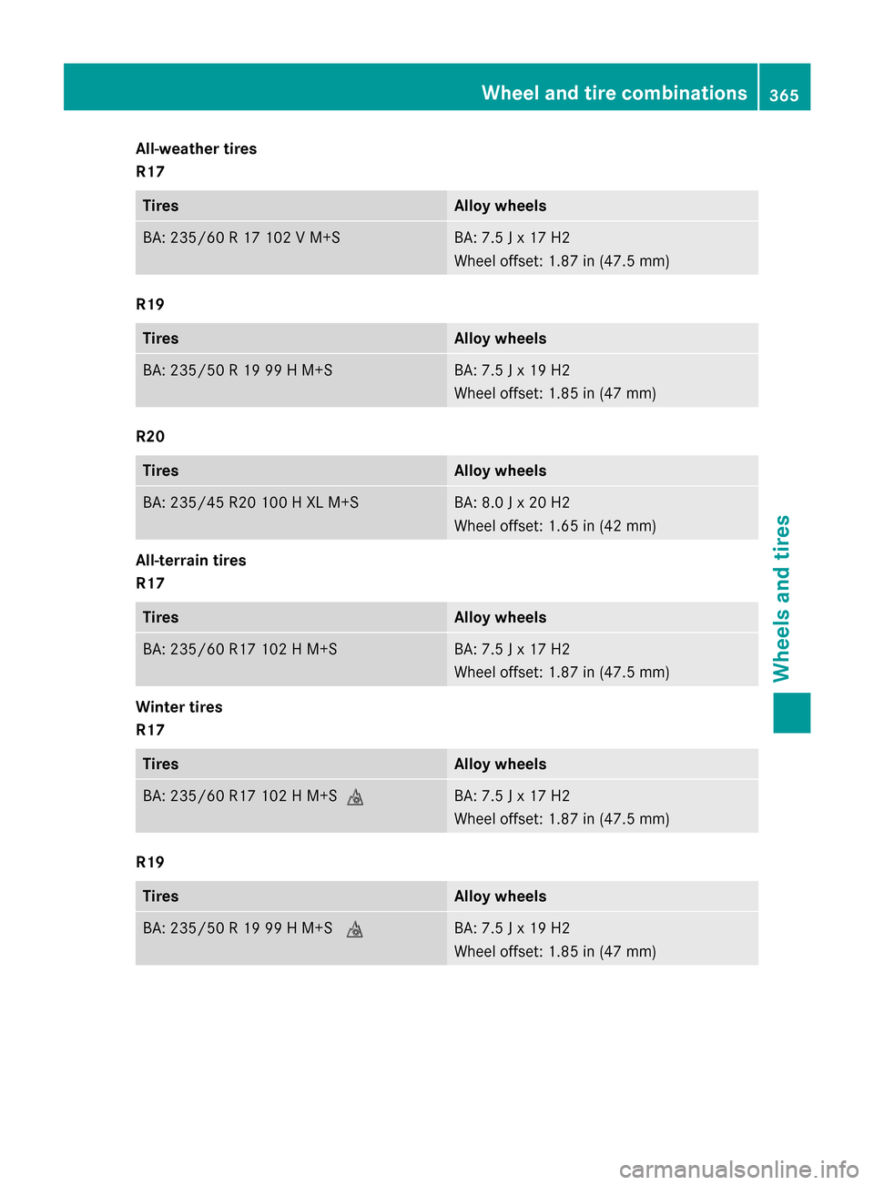
All-weather tires
R17
Tires Alloy wheels
BA: 235/60 R 17 102 V M+S BA: 7.5 J x 17 H2
Wheel offset: 1.87 in (47.5 mm)
R19
Tires Alloy wheels
BA: 235/50 R 19 99 H M+S BA: 7.5 J x 19 H2
Wheel offset: 1.85 in (47 mm)
R20
Tires Alloy wheels
BA: 235/45 R20 100 H XL M+S BA: 8.0 J x 20 H2
Wheel offset: 1.65 in (42 mm)
All-terrain tires
R17
Tires Alloy wheels
BA: 235/60 R17 102 H M+S BA: 7.5 J x 17 H2
Wheel offset: 1.87 in (47.5 mm)
Winter tires
R17
Tires Alloy wheels
BA: 235/60 R17 102 H M+S004D BA: 7.5 J x 17 H2
Wheel offset: 1.87 in (47.5 mm)
R19
Tires Alloy wheels
BA: 235/50 R 19 99 H M+S
004D BA: 7.5 J x 19 H2
Wheel offset: 1.85 in (47 mm) Wheel and tire combinations
365Wheels and tires Z
Page 368 of 386
Emergency spare wheel
Important safety notes
G
WARNING
The wheel or tire size as well as the tire type of the spare wheel or emergency spare wheel
and the wheel to be replaced may differ.
Mounting an emergency spare wheel may
severely impair the driving characteristics.
There is a risk of an accident.
To avoid hazardous situations:
R adapt your driving style accordingly and
drive carefully.
R never mount more than one spare wheel or
emergency spare wheel that differs in size.
R only use a spare wheel or emergency spare
wheel of a different size briefly.
R do not switch ESP ®
off.
R have a spare wheel or emergency spare
wheel of a different size replaced at the
nearest qualified specialist workshop.
Observe that the wheel and tire dimensions
as well as the tire type must be correct.
When using an emergency spare wheel or
spare wheel of a different size, you must not
exceed the maximum speed of 50 mph
(80 km/h).
Snow chains must not be mounted on emer-
gency spare wheels. General notes
You should regularly check the pressure of
the emergency spare wheel, particularly prior
to long trips, and correct the pressure as nec-
essary (Y page 336). The applicable value can
be found on the wheel or under "Technical
data" (Y page 360).
i When you are driving with the emergency
spare wheel mounted, the tire pressure
monitor cannot function reliably. Only
restart the tire pressure monitor when the
defective wheel has been replaced with a
new wheel. If an emergency spare wheel is mounted,
the system may continue to show the tire
pressure of the wheel that has been
removed for a few minutes. The value dis-
played for the mounted emergency spare
wheel is not the same as the current tire
pressure of the emergency spare wheel.
An emergency spare wheel may also be
mounted against the direction of rotation.
Observe the time restriction on use as well as
the speed limitation specified on the emer-
gency spare wheel.
Replace the tires after six years at the latest, regardless of wear. This also applies to the
emergency spare wheel. Collapsible spare wheel
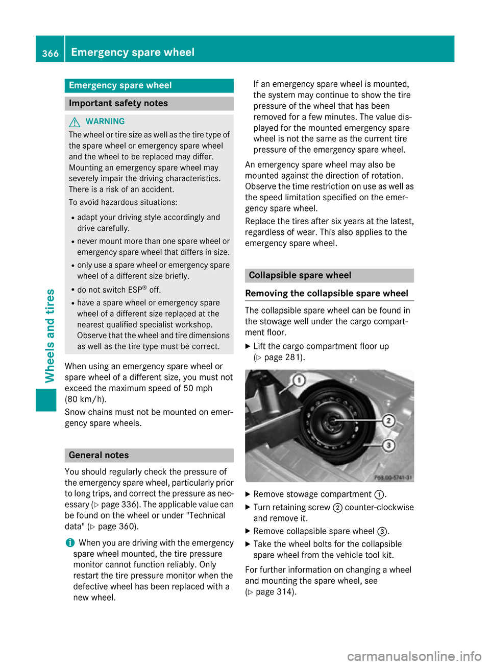
Removing the collapsible spare wheel The collapsible spare wheel can be found in
the stowage well under the cargo compart-
ment floor.
X Lift the cargo compartment floor up
(Y page 281). X
Remove stowage compartment 0043.
X Turn retaining screw 0044counter-clockwise
and remove it.
X Remove collapsible spare wheel 0087.
X Take the wheel bolts for the collapsible
spare wheel from the vehicle tool kit.
For further information on changing a wheel
and mounting the spare wheel, see
(Y page 314). 366
Emergency spare wheelWheels and tires