transmission MERCEDES-BENZ GLK-Class 2015 X204 Service Manual
[x] Cancel search | Manufacturer: MERCEDES-BENZ, Model Year: 2015, Model line: GLK-Class, Model: MERCEDES-BENZ GLK-Class 2015 X204Pages: 386, PDF Size: 7.16 MB
Page 195 of 386
then have to steer and merge into traffic on
your own. PARKTRONIC is still available.
Canceling Active Parking Assist You can cancel Active Parking Assist at any
time.
X Stop the movement of the multifunction
steering wheel or steer yourself.
Active Parking Assist will be canceled at
once. The Park Assist Canceled Park Assist Canceled mes-
sage appears in the multifunction display.
or
X Press the PARKTRONIC button on the cen-
ter console (Y page 188).
PARKTRONIC is switched off and Active
Parking Assist is immediately canceled.
The Park Assist Canceled Park Assist Canceled message
appears in the multifunction display.
Active Parking Assist is canceled automati-
cally if: R the electric parking brake is engaged
R transmission position Pis selected
R parking using Active Parking Assist is no
longer possible
R you are driving faster than 6 mph (10 km/h)
R a wheel spins, ESP ®
intervenes or fails. The
00E5 warning lamp lights up in the instru-
ment cluster.
A warning tone sounds. The parking symbol
disappears and the multifunction display
shows the Park Assist Canceled
Park Assist Canceled mes-
sage.
If Active Parking Assist is canceled, you must
steer again yourself.
If a system malfunction occurs, the vehicle is braked to a standstill. To drive on, depress the
accelerator again.
Towing a trailer For vehicles with a trailer tow hitch, the min-
imum length for parking spaces is slightly
increased. If you have attached a trailer to your vehicle,
you should not use Active Parking Assist.
Once the electrical connection is established
between your vehicle and the trailer, Active
Parking Assist is no longer available. PARK-
TRONIC is deactivated for the rear area. Rear view camera
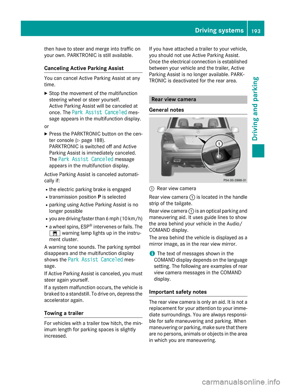
General notes 0043
Rear view camera
Rear view camera 0043is located in the handle
strip of the tailgate.
Rear view camera 0043is an optical parking and
maneuvering aid. It uses guide lines to show
the area behind your vehicle in the Audio/
COMAND display.
The area behind the vehicle is displayed as a
mirror image, as in the rear view mirror.
i The text of messages shown in the
COMAND display depends on the language
setting. The following are examples of rear view camera messages in the COMAND
display.
Important safety notes The rear view camera is only an aid. It is not a
replacement for your attention to your imme- diate surroundings. You are always responsi-
ble for safe maneuvering and parking. When
maneuvering or parking, make sure that there are no persons, animals or objects in the area
in which you are maneuvering. Driving systems
193Driving and parking Z
Page 196 of 386
Under the following circumstances, the rear
view camera will not function, or will function
in a limited manner:
R if the tailgate is open
R in heavy rain, snow or fog
R at night or in very dark places
R if the camera is exposed to very bright light
R if the area is lit by fluorescent bulbs or LED
lighting (the display may flicker)
R if there is a sudden change in temperature,
e.g. when driving into a heated garage in
winter
R if the camera lens is dirty or obstructed
R if the rear of your vehicle is damaged. In this
event, have the camera position and setting checked at a qualified specialist workshop
The field of vision and other functions of the
rear view camera may be restricted due to
additional accessories on the rear of the vehi-
cle (e.g. license plate holder, bicycle rack).
Activating/deactivating the rear view
camera X
To activate: make sure that the SmartKey
is in position 2in the ignition lock.
X Make sure that the "Activation by R gear"
setting is active in COMAND, see the sep-
arate COMAND operating instructions.
X Engage reverse gear.
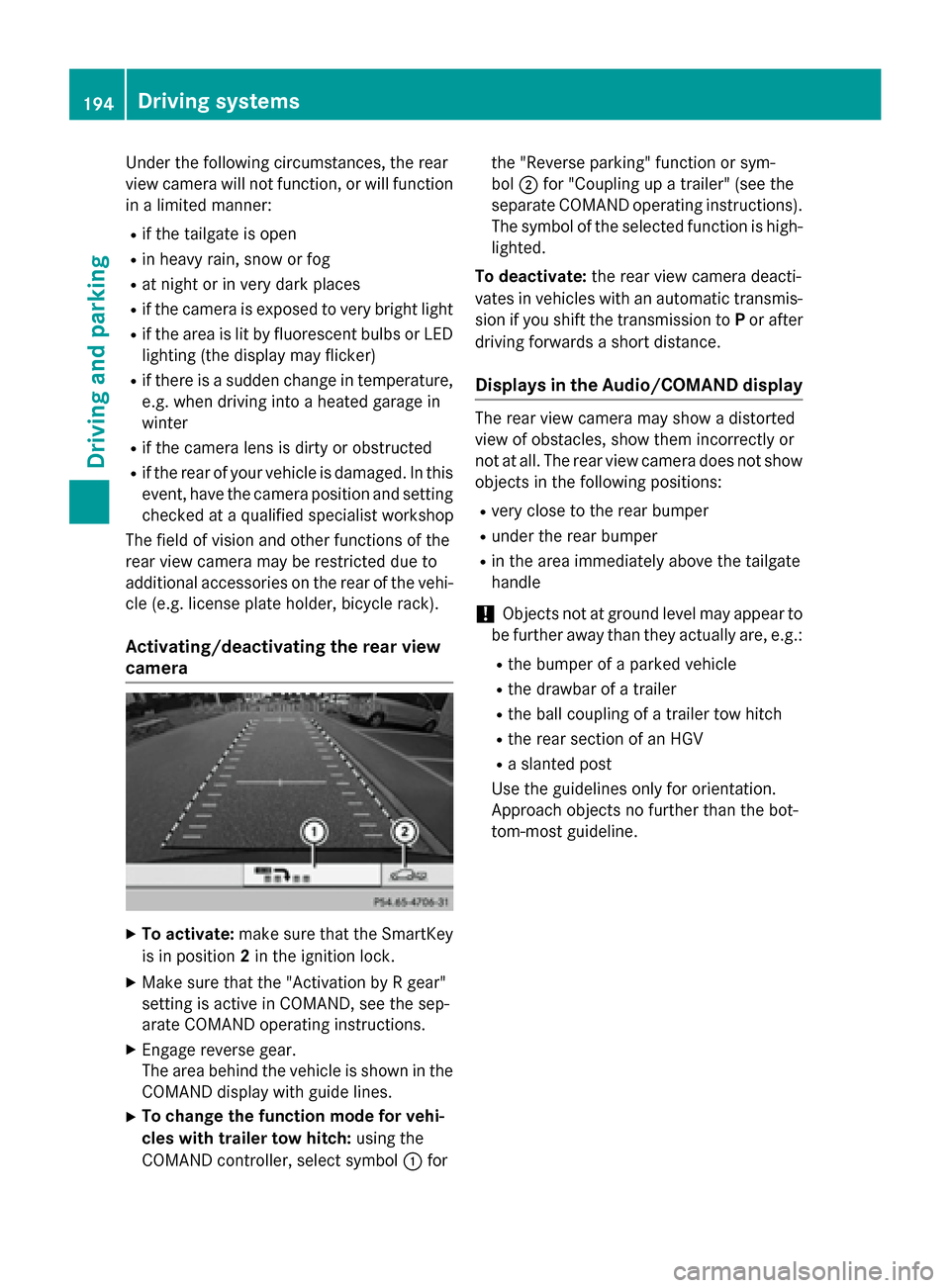
The area behind the vehicle is shown in the
COMAND display with guide lines.
X To change the function mode for vehi-
cles with trailer tow hitch: using the
COMAND controller, select symbol 0043for the "Reverse parking" function or sym-
bol
0044for "Coupling up a trailer" (see the
separate COMAND operating instructions). The symbol of the selected function is high- lighted.
To deactivate: the rear view camera deacti-
vates in vehicles with an automatic transmis-
sion if you shift the transmission to Por after
driving forwards a short distance.
Displays in the Audio/COMAND display The rear view camera may show a distorted
view of obstacles, show them incorrectly or
not at all. The rear view camera does not show
objects in the following positions:
R very close to the rear bumper
R under the rear bumper
R in the area immediately above the tailgate
handle
! Objects not at ground level may appear to
be further away than they actually are, e.g.:
R the bumper of a parked vehicle
R the drawbar of a trailer
R the ball coupling of a trailer tow hitch
R the rear section of an HGV
R a slanted post
Use the guidelines only for orientation.
Approach objects no further than the bot-
tom-most guideline. 194
Driving systemsDriving and parking
Page 200 of 386
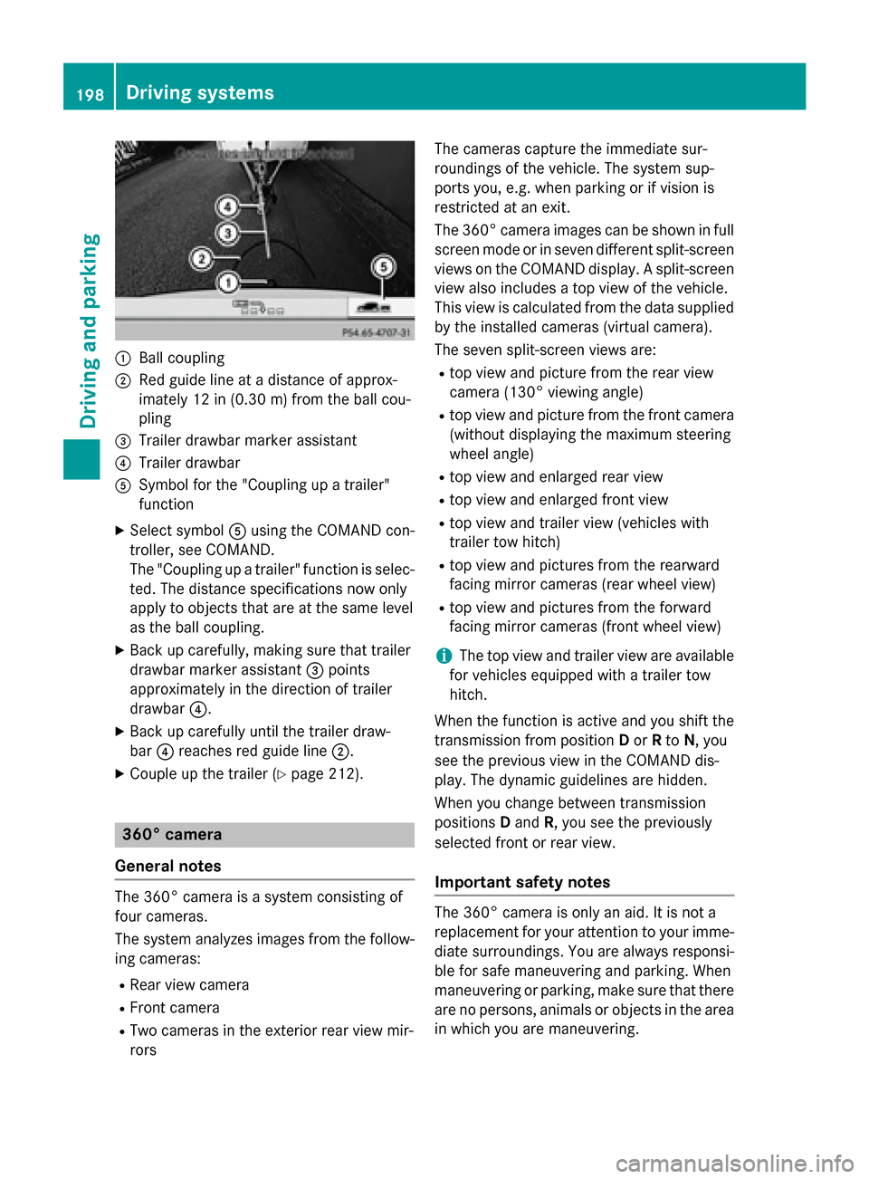
0043
Ball coupling
0044 Red guide line at a distance of approx-
imately 12 in (0.30 m)from the ball cou-
pling
0087 Trailer drawbar marker assistant
0085 Trailer drawbar
0083 Symbol for the "Coupling up a trailer"
function
X Select symbol 0083using the COMAND con-
troller, see COMAND.
The "Coupling up a trailer" function is selec-
ted. The distance specifications now only
apply to objects that are at the same level
as the ball coupling.
X Back up carefully, making sure that trailer
drawbar marker assistant 0087points
approximately in the direction of trailer
drawbar 0085.
X Back up carefully until the trailer draw-
bar 0085reaches red guide line 0044.
X Couple up the trailer (Y page 212).360° camera
General notes The 360° camera is a system consisting of
four cameras.
The system analyzes images from the follow- ing cameras:
R Rear view camera
R Front camera
R Two cameras in the exterior rear view mir-
rors The cameras capture the immediate sur-
roundings of the vehicle. The system sup-
ports you, e.g. when parking or if vision is
restricted at an exit.
The 360° camera images can be shown in full
screen mode or in seven different split-screen views on the COMAND display. A split-screenview also includes a top view of the vehicle.
This view is calculated from the data supplied
by the installed cameras (virtual camera).
The seven split-screen views are: R top view and picture from the rear view
camera (130° viewing angle)
R top view and picture from the front camera
(without displaying the maximum steering
wheel angle)
R top view and enlarged rear view
R top view and enlarged front view
R top view and trailer view (vehicles with
trailer tow hitch)
R top view and pictures from the rearward
facing mirror cameras (rear wheel view)
R top view and pictures from the forward
facing mirror cameras (front wheel view)
i The top view and trailer view are available
for vehicles equipped with a trailer tow
hitch.
When the function is active and you shift the
transmission from position Dor Rto N, you
see the previous view in the COMAND dis-
play. The dynamic guidelines are hidden.
When you change between transmission
positions Dand R, you see the previously
selected front or rear view.
Important safety notes The 360° camera is only an aid. It is not a
replacement for your attention to your imme-
diate surroundings. You are always responsi-
ble for safe maneuvering and parking. When
maneuvering or parking, make sure that there are no persons, animals or objects in the area
in which you are maneuvering. 198
Driving systemsDriving and parking
Page 214 of 386
R
a driving safety system intervenes, e.g.
ESP ®
, PRE-SAFE ®
Brake or Active Blind
Spot Assist.
R you have adopted a sporty driving style with
high cornering speeds or high rates of
acceleration.
R on vehicles with a trailer tow hitch, the
electrical connection to the trailer has been
correctly established.
R ESP ®
is switched off.
R the transmission is not in position D.
R a loss of tire pressure or a defective tire has
been detected and displayed.
Active Lane Keeping Assist does not detect
traffic situations or road users. An inappro-
priate brake application may be interrupted at any time if you:
R steer slightly in the opposite direction
R you have switched on the turn signals
R clearly brake or accelerate
A lane-correcting brake application is inter-
rupted automatically if:
R a driving safety system intervenes, e.g.
ESP ®
, PRE-SAFE ®
Brake or Active Blind
Spot Assist.
R lane markings can no longer be recognized.
Switching on Active Lane Keeping Assist
X Switch on Active Lane Keeping Assist using
the on-board computer; to do so, select
Standard
Standard orAdaptive Adaptive (Ypage 230).
If you drive at speeds above 40 mph
(60 km/h) and lane markings are detected, the lines in the assistance graphics display(Y page 229) are shown in green. Lane
Keeping Assist is ready for use.
If Standard
Standard is selected, no warning vibra-
tion occurs if:
R you have switched on the turn signals. In
this event, the warnings are suppressed
for a certain period of time.
R a driving safety system intervenes, such
as ABS, BAS or ESP ®
. When
Adaptive Adaptive is selected, no warning
vibration occurs if:
R you have switched on the turn signals. In
this event, the warnings are suppressed
for a certain period of time.
R a driving safety system intervenes, e.g.
ABS, BAS or ESP ®
.
R you accelerate hard, e.g. kickdown.
R you brake hard.
R you steer actively, e.g. swerve to avoid an
obstacle or change lanes quickly.
R you cut the corner on a sharp bend.
Towing a trailer
When you attach a trailer, make sure you have correctly established the electrical connec-
tion. This can be accomplished by checking
the trailer lighting. Towing a trailer
Notes on towing a trailer
Important safety notes G
WARNING
If you rest your foot on the brake pedal while
driving, the braking system can overheat. This increases the stopping distance and can even
cause the braking system to fail. There is a
risk of an accident.
Never use the brake pedal as a footrest. Never
depress the brake pedal and the accelerator
pedal at the same time. G
WARNING
When the vehicle/trailer combination begins
to lurch, you could lose control of it. The vehi- cle/trailer combination could even rollover.
There is a risk of an accident.
On no account should you attempt to
straighten up the vehicle/trailer combination
by increasing the speed. Reduce vehicle
speed and do not countersteer. Apply the
brake as necessary. 212
Towing a trailerDriving and parking
Page 217 of 386
G
WARNING
If the ball coupling is not correctly installed
and secured, it could come loose while driving and endanger other road users. There is a risk
of an accident and injury.
Install and secure the ball coupling as descri-
bed in the ball coupling manufacturer's instal- lation instructions. Make sure that the ball
coupling is correctly installed and secured
before every journey. Coupling up a trailer
Observe the maximum permissible trailer
dimensions (width and length).
Most U.S. states and all Canadian provinces
require by law: R safety chains between the towing vehicle
and the trailer. The chains should be cross-
wound under the trailer drawbar. They must be fastened to the vehicle's trailer cou-
pling, not to the bumper or the axle.
Leave enough play in the chains to make
tight cornering possible.
R a separate brake system for certain types
of trailer.
R a safety switch for braked trailers. Check
the specific legal requirements applicable
to your state.
If the trailer detaches from the towing vehi-
cle, the safety switch applies the trailer's
brakes.
! Do not connect the trailer's brake system
(if featured) to the hydraulic brake system
of the towing vehicle, as the latter is equip-
ped with an anti-lock brake system. Doing
so will result in a loss of function of the
brake systems of both the vehicle and the
trailer.
i The vehicle's wiring harness features a
connection to the brake indicator lamp. X
Make sure that the automatic transmission
is set to position P.
X Apply the vehicle's parking brake.
X Close all doors and the tailgate.
X Couple up the trailer.
X Establish all electrical connections. Towing a trailer
There are numerous legal requirements con-
cerning the towing of a trailer, e.g. speed
restrictions. Make sure that your car/trailer
combination complies with the local regula-
tions:
R in your place of residence
R in the location to which you are driving
The police and local authorities can provide
reliable information.
Observe the following when towing a trailer:
R To gain driving experience and to become
accustomed to the new handling charac-
teristics, you should practice the following
in a traffic-free location:
- cornering
- stopping
- backing up
R Before driving, check:
- the trailer tow hitch
- the safety switch for braked trailers
- the safety chains
- electrical connections
- the lights
- the wheels
R Adjust the exterior mirrors to provide an
unobstructed view of the rear section of the
trailer.
R If the trailer has electronically controlled
brakes, pull away carefully. Brake manually
using the brake controller and check
whether the brakes function correctly.
R Secure any objects on the trailer to prevent
the cargo from slipping when the vehicle is
in motion. Towing a trailer
215Driving and parking Z
Page 218 of 386
R
When you couple up a trailer, check at reg-
ular intervals that the load is firmly secured.If the trailer is equipped with trailer lights
and brakes, check the trailer to ensure that
these are working.
R Bear in mind that the handling will be less
stable when towing a trailer than when driv-
ing without one. Avoid sudden steering
movements.
R The vehicle/trailer combination is heavier,
accelerates more slowly, has a decreased
gradient climbing capability and a longer
braking distance.
It is more susceptible to side winds and
requires more careful steering.
R If possible, avoid abrupt braking. Depress
the brake pedal moderately at first, so that the trailer can activate its own brakes. Thenincrease the pressure on the brake pedal.
R If the automatic transmission repeatedly
shifts between gears on uphill or downhill
gradients, shift to a lower gear using the
left-hand steering wheel paddle shifter.
A lower gear and lower speed reduce the
risk of engine failure.
R When driving downhill, shift to a lower gear
to utilize the engine's braking effect.
Avoid continuous brake application as this
may overheat the vehicle brakes and, if
installed, the trailer brakes.
R If the coolant temperature increases dra-
matically while the air-conditioning system
is switched on, switch off the air-condition-
ing system.
Coolant heat can additionally be dissipated
by opening the windows and by setting the
blower fan and the interior temperature to
maximum.
R When overtaking, pay particular attention
to the extended length of your vehicle/
trailer combination.
Due to the length of the vehicle/trailer
combination, you require additional road
space in relation to the vehicle you are
overtaking, before you can change back to
the original lane. Decoupling a trailer
G
WARNING
If you uncouple a trailer with the overrun
brake engaged, you could trap your hand
between the vehicle and the trailer drawbar.
There is a risk of injury.
Do not uncouple a trailer if the overrun brake is engaged.
! Do not disconnect a trailer with an
engaged overrun brake. Otherwise, your
vehicle could be damaged by the rebound- ing of the overrun brake.
X Make sure that the automatic transmission
is set to position P.
X Apply the vehicle's parking brake.
X Close all doors and the tailgate.
X Apply the trailer's parking brake.
X Remove the trailer cable and decouple the
trailer. Permissible trailer loads and drawbar
loads
Weight specifications The gross trailer weight is calculated by add-
ing the weight of the trailer to the weight of
the load and equipment on the trailer.
You will find installing dimensions and loads
under "Technical data" (Y
page 381).
Loading a trailer R
When loading the trailer, make sure that
neither the permissible gross weight of the
trailer nor the gross vehicle weight is
exceeded. The permissible gross vehicle
weight is indicated on the identification
plate on the B-pillar on the driver's side of
the vehicle.
You can find the maximum permissible val-
ues on the type plates of your vehicle and
the trailer. When calculating how much
weight the vehicle and trailer may carry, 216
Towing a trailerDriving and parking
Page 224 of 386
0063
0064 Press and hold:
R In the Audio
Audio menu: selects the
previous/next station or selects
an audio track or a video scene
using rapid scrolling
R In the Tel Tel(Telephone) menu:
starts rapid scrolling of the
phone book if it is open 0076 R
Confirms a selection/display
message
R In the Tel
Tel (Telephone) menu:
switches to the telephone book
and starts dialing the selected
number
R In the Audio Audio menu: stops the
station search function at the
desired station Right control panel
0076 R
Rejects or ends a call
R Exits phone book/redial mem-
ory 0061 R
Makes or accepts a call
R Switches to the redial memory 0081
0082 R
Adjusts the volume 0063 R
Mute Back button
0038 Press briefly:
R Back
R Switches off the Voice Control
System; see the separate oper-
ating instructions
R Hides display messages/calls
up the last Trip
Trip menu function
used
R Exits the telephone book/redial
memory 0038 Press and hold:
R Calls up the standard display in
the Trip Trip menu Multifunction display
Values and settings as well as display mes-
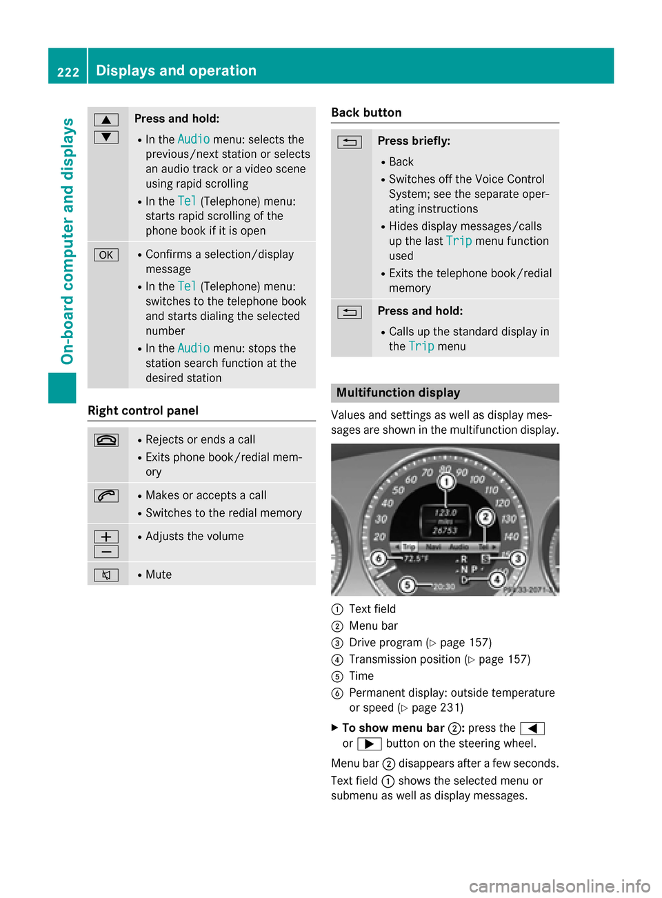
sages are shown in the multifunction display. 0043
Text field
0044 Menu bar
0087 Drive program (Y page 157)
0085 Transmission position (Y page 157)
0083 Time
0084 Permanent display: outside temperature
or speed (Y page 231)
X To show menu bar 0044:press the 0059
or 0065 button on the steering wheel.
Menu bar 0044disappears after a few seconds.
Text field 0043shows the selected menu or
submenu as well as display messages. 222
Displays and operationOn-board computer and displays
Page 260 of 386
Vehicle
Display messages
Possible causes/consequences and
0050
0050Solutions Shift
Shift
to
to'P'
'P' or
or'N'
'N'
to Start Engine
to Start Engine You have attempted to start the engine with the transmission in
position Ror D.
X Shift the transmission to position Por N. Risk of rolling
Risk of rolling
Select Park (P) Select Park (P) You have attempted to stop the engine with the Start/Stop button
while the transmission was not in position P.
G WARNING
The vehicle may roll away.
There is a risk of an accident. X Shift the transmission to position P.
X Secure the vehicle against rolling away (Y page 168).0065 The tailgate is open.
G WARNING
When the engine is running, exhaust gases can enter the vehicle
interior if the tailgate is open.
There is a risk of poisoning.
X Close the tailgate. 0066 The hood is open.
G WARNING
The open hood may block your view when the vehicle is in motion.
There is a risk of an accident.
X Pull over and stop the vehicle safely as soon as possible, paying
attention to road and traffic conditions.
X Secure the vehicle against rolling away (Y page 168).
X Close the hood. 0051 At least one door is open.
X Close all the doors. 258
Display messagesOn-board computer and displays
Page 298 of 386
X
Turn the SmartKey to position 2in the igni-
tion lock (Y page 149).
X Select one of buttons 0044to0085 to use to
control the garage door drive.
X To start programing mode: press and
hold one of buttons 0044to0085 on the inte-
grated garage door opener.
The garage door opener is now in program- ing mode. After a short time, indicator
lamp 0043lights up yellow.
Indicator lamp 0043lights up yellow as soon
as button 0044,0087or0085 is programed for the
first time. If the selected button has already been programed, indicator lamp 0043will
only light up yellow after ten seconds have elapsed.
X Release button 0044,0087or0085. Indicator
lamp 0043flashes yellow.
X To program the remote control: point
garage door remote control 0083towards
buttons 0044to0085 on the rear-view mirror at
a distance of 2 to 8 inches (5 to 20 cm).
X Press and hold button 0084on remote control
0083 until indicator lamp 0043lights up green.
When indicator lamp 0043lights up green:
programing is finished.
When indicator lamp 0043flashes green: pro-
graming was successful. The next step is to
synchronize the rolling code.
X Release button 0084on remote control 0083for
the garage door drive system.
If indicator lamp 0043lights up red: repeat the
programing procedure for the correspond-
ing button on the rear-view mirror. When
doing so, vary the distance between remote
control 0083and the rear-view mirror.
The required distance between remote
control 0083and the integrated garage door
opener depends on the garage door drive
system. Several attempts might be neces-
sary. You should test every position for at
least 25 seconds before trying another
position. Synchronizing the rolling code
Pay attention to the "Important safety notes"
(Y page 295).
If the garage door system uses a rolling code,
you will also have to synchronize the garage
door system with the integrated garage door
opener in the rear-view mirror. To do this you
will need to use the programing button on the door drive control panel. The programing but-
ton may be positioned at different locations
depending on the manufacturer. It is usually
located on the door drive unit on the garage
ceiling.
Familiarize yourself with the garage door
drive operating instructions, e.g. under "Pro-
graming of additional remote controls",
before carrying out the following steps.
Your vehicle must be within reach of the
garage door or gate opener drive. Make sure
that neither your vehicle nor any persons/
objects are present within the sweep of the
door or gate.
X Turn the SmartKey to position 2in the igni-
tion lock (Y page 149).
X Get out of the vehicle.
X Press the programing button on the door
drive unit.
Usually, you now have 30 seconds to ini-
tiate the next step.
X Get into the vehicle.
X Press previously programed button 0044,0087
or 0085 on the integrated garage door opener
until the door closes.
The rolling code synchronization is then
complete.
Notes on programing the remote control
Canadian radio frequency laws require a
"break" (or interruption) of the transmission
signals after broadcasting for a few seconds.
Therefore, these signals may not last long
enough for the integrated garage door
opener. The signal is not recognized during
programing. Comparable with Canadian law,
some U.S. garage door openers also feature a "break". 296
FeaturesStowage and features
Page 299 of 386
Proceed as follows:
R if you live in Canada
R if you have difficulties programing the
garage door opener (regardless of where
you live) when using the programing steps.
X Press and hold one of buttons 0044to0085 on
the integrated garage door opener.
After a short time, indicator lamp 0043lights
up yellow.
X Release the button.
Indicator lamp 0043flashes yellow.
X Press button 0084of garage door remote
control 0083for two seconds, then release it
for two seconds.
X Press button 0084again for two seconds.
X Repeat this sequence on button 0084of
remote control 0083until indicator lamp 0043
lights up green.
When indicator lamp 0043lights up green:
programing is finished.
When indicator lamp 0043flashes green: pro-
graming was successful. The next step is to
synchronize the rolling code.
X Release button 0084of remote control 0083of
the garage door drive.
If indicator lamp 0043lights up red: repeat the
programing process for the corresponding
button on the rear-view mirror. When doing
so, vary the distance between remote con- trol 0083and the rear-view mirror.
The required distance between remote
control 0083and the integrated garage door
opener depends on the garage door drive
system. Several attempts might be neces-
sary. You should test every position for at
least 25 seconds before trying another
position.
Problems when programing
If you are experiencing problems programing
the integrated garage door opener on the
rear-view mirror, take note of the following
instructions:
R Check the transmitter frequency used by
garage door drive remote control 0083and whether it is supported. The transmitter
frequency can usually be found on the back
of the garage door drive remote control.
The integrated garage door opener is com-
patible with devices that have units which
operate in the frequency range of 280 to
433 MHz.
R Replace the batteries in garage door
remote control 0083. This increases the like-
lihood that garage door remote control 0083
will transmit a strong and precise signal to the integrated garage door opener.
R When programing, hold remote control 0083
at varying distances and angles from the
button which you are programing. Try vari-
ous angles at a distance between 2and
12 inches (5to 30 cm) or at the same angle but at varying distances.
R If another remote control is available for the
same garage door drive, repeat the same
programing steps with this remote control. Before performing these steps, make sure
that new batteries have been installed in
garage door drive remote control 0083.
R Note that some remote controls only trans-
mit for a limited amount of time (the indi-
cator lamp on the remote control goes out).
Press button 0084on remote control 0083again
before transmission ends.
R Align the antenna cable of the garage door
opener unit. This can improve signal recep-tion/transmission.
Opening/closing the garage door After it has been programed, the integrated
garage door opener performs the function of
the garage door system remote control.
Please also read the operating instructions
for the garage door system.
X Turn the SmartKey to position 2in the igni-
tion lock (Y page 149).
X Press button 0044,0087or0085 which you have
programed to operate the garage door.
Garage door system with a fixed code: indi-
cator lamp 0043lights up green. Features
297Stowage and features Z