lock MERCEDES-BENZ GLK-CLASS SUV 2013 Owners Manual
[x] Cancel search | Manufacturer: MERCEDES-BENZ, Model Year: 2013, Model line: GLK-CLASS SUV, Model: MERCEDES-BENZ GLK-CLASS SUV 2013Pages: 380, PDF Size: 19.54 MB
Page 341 of 380
pressure monitor then monitors the new tire
pressure values.
Restart the tire pressure monitor after you
have set the tire pressure to the value
recommended for the desired driving
situation (
Y page 331). Only correct tire
pressures on cold tires. Comply with the
recommended tire pressures on the Tire and
Loading Information placard the B-pillar on
the driver's side. Additional tire pressure
values for driving at high
speeds or with heavy
loads can be found in the tire pressure table
on the inside of the fuel filler flap.
X Make sure that the tire pressure is correct
on all four wheels.
X Make sure that the SmartKey is in position
2 in the ignition lock.
X Press the 0059 or 0065 button on the
steering wheel to select the Service
menu.
X Press the 0063 or 0064 button to select
Tire Pressure.
X Press the 0076 button.
The multifunction display shows the
current tire pressure for the
individual tires
or the Tire pressures will be
displayed after driving a few
minutes message.
X Press the 0064 button.
The Use Current Pressures as New
Reference Values message appears in
the multifunction display.
If you wish to confirm the restart:
X Press the 0076 button.
The Tire Press. Monitor Restarted
message appears in the multifunction
display.
After driving for a
few
minutes, the system
checks whether the current tire pressures
are within the specified range. The new tire
pressures are then accepted as reference
values and monitored. If you wish to cancel the restart:
X
Press the 0038 button.
The tire pressure values stored at the last
restart will continue to be monitored. Loading the vehicle
Instruction labels for tires and loads
G
WARNING
Overloaded tires can overheat, causing a
blowout. Overloaded tires can also
impair the
steering and driving characteristics and lead
to brake failure. There is a risk of accident.
Observe the load rating of the tires. The load
rating must be at least half of the GAWR of
your vehicle. Never overload the tires by
exceeding the maximum load.
Two instruction labels on your vehicle show
the maximum possible load.
(1) The Tire and Loading Information placard is on the B-pillar
on the driver's side. The
Tire and Loading Information placard
shows the maximum permissible number
of occupants and the maximum
permissible vehicle load. It also contains
details of the tire sizes and
corresponding pressures for tires
mounted at the factory.
(2) The vehicle identification plate is on the B-pillar on the driver's side. The vehicle
identification plate informs you of the
gross vehicle weight rating. It
is made up
of the vehicle weight, all vehicle
occupants, the fuel and the cargo. You
can also find information about the
maximum gross axle weight rating on the
front and rear axle.
The maximum gross axle weight rating is
the maximum weight that can be carried
by one axle (front or rear axle). Never
exceed the maximum load or the
maximum gross axle weight rating for the
front or rear axle. Loading the vehicle
339
Wheels and tires Z
Page 355 of 380
Cleaning the wheels
G
WARNING
The water jet from a circular jet nozzle (dirt
blasters) can cause invisible exterior
damage
to the tires or chassis components.
Components damaged in this way may fail
unexpectedly. There is a risk of an accident.
Do not use power washers with circular jet
nozzles to clean the vehicle. Have damaged
tires or chassis components replaced
immediately. Mounting a wheel
Preparing the vehicle
X Stop the vehicle on solid, non-slippery and
level ground.
X Apply the parking brake.
X Bring the front wheels into the straight-
ahead position.
X Secure the vehicle against rolling away
(Y page 160).
X Switch off the engine.
X Vehicles without KEYLESS-GO: remove
the SmartKey from the ignition lock.
X Vehicles with KEYLESS-GO: open the
driver's door.
The on-board electronics have status 0,
which is the same as the SmartKey having
been removed.
X Vehicles with KEYLESS-GO: remove the
Start/Stop button from the ignition lock
(Y page 141).
X If included in the vehicle equipment,
remove the tire-change tool kit from the
vehicle.
X Secure the vehicle to prevent it from rolling
away. Securing the vehicle to prevent it
from rolling away
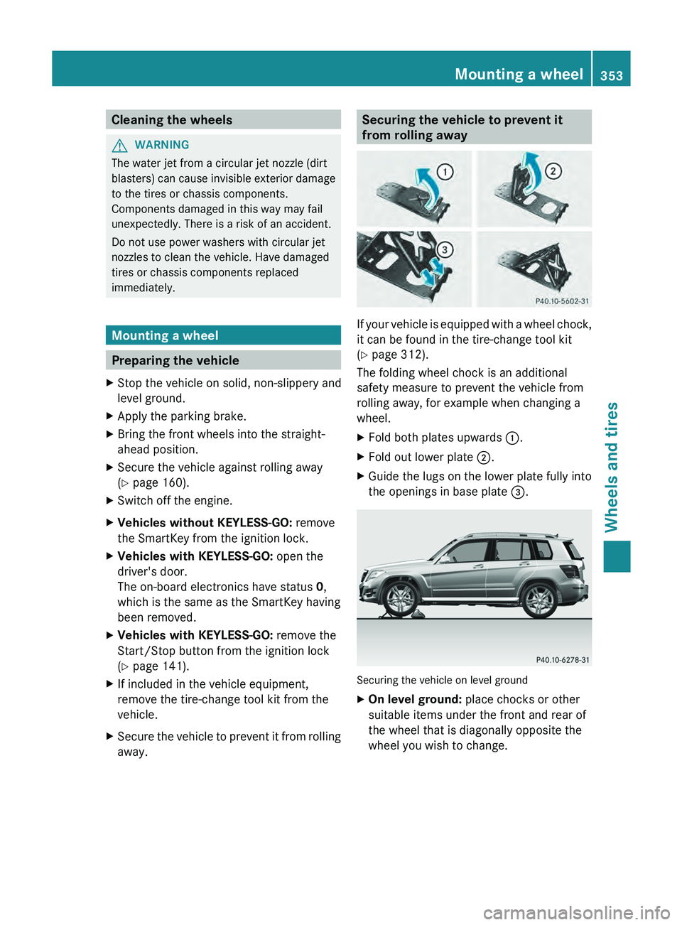
If your vehicle is equipped with a wheel chock,
it can be found in the tire-change tool kit
(Y page 312).
The folding wheel chock is an additional
safety measure to prevent the vehicle from
rolling away, for example when changing a
wheel.
X
Fold both plates upwards 0043.
X Fold out lower plate 0044.
X Guide the lugs on the lower plate fully into
the openings in base plate 0087. Securing the vehicle on level ground
X
On level ground: place chocks or other
suitable items under the front and rear of
the wheel that is diagonally opposite the
wheel you wish to change. Mounting a wheel
353
Wheels and tires Z
Page 356 of 380
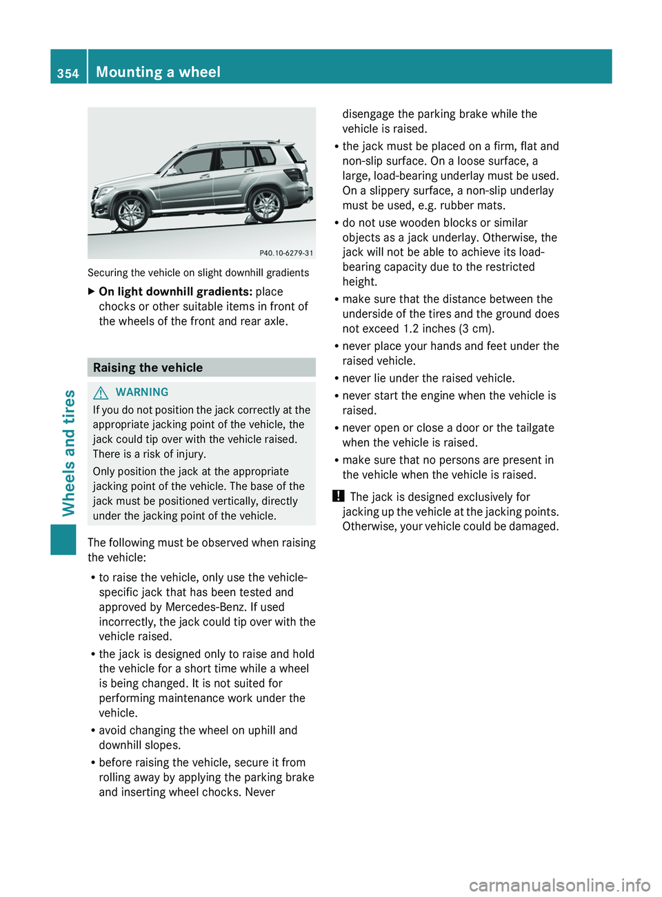
Securing the vehicle on slight downhill gradients
X
On light downhill gradients: place
chocks or other suitable items in front of
the wheels of the front and rear axle. Raising the vehicle
G
WARNING
If you do not position the jack correctly at the
appropriate jacking point of the vehicle, the
jack could tip over with the vehicle raised.
There is a risk of injury.
Only position the jack at the appropriate
jacking point of the vehicle. The base of the
jack must be positioned vertically, directly
under the jacking point of the vehicle.
The following must be observed
when raising
the vehicle:
R to raise the vehicle, only use the vehicle-
specific jack that has been tested and
approved by Mercedes-Benz. If used
incorrectly, the jack could tip over with the
vehicle raised.
R the jack is designed only to raise and hold
the vehicle for a short time while a wheel
is being changed. It is not suited for
performing maintenance work under the
vehicle.
R avoid changing the wheel on uphill and
downhill slopes.
R before raising the vehicle, secure it from
rolling away by applying the parking brake
and inserting wheel chocks. Never disengage the parking brake while the
vehicle is raised.
R the jack must be placed on a firm, flat and
non-slip surface. On a loose surface, a
large, load-bearing underlay
must be
used.
On a slippery surface, a non-slip underlay
must be used, e.g. rubber mats.
R do not use wooden blocks or similar
objects as a jack underlay. Otherwise, the
jack will not be able to achieve its load-
bearing capacity due to the restricted
height.
R make sure that the distance between the
underside of the tires and the ground does
not exceed 1.2 inches (3 cm).
R never place your hands and feet under the
raised vehicle.
R never lie under the raised vehicle.
R never start the engine when the vehicle is
raised.
R never open or close a door or the tailgate
when the vehicle is raised.
R make sure that no persons are present in
the vehicle when the vehicle is raised.
! The jack is designed exclusively for
jacking up the vehicle at the jacking points.
Otherwise, your vehicle could be damaged. 354
Mounting a wheel
Wheels and tires
Page 362 of 380
R
only use a spare wheel or emergency spare
wheel of a different size briefly.
R do not switch ESP ®
off.
R have a spare wheel or emergency spare
wheel of a different size replaced at the
nearest qualified specialist workshop.
Observe that the wheel and tire dimensions
as well as the tire type must be correct.
When using an emergency spare wheel or
spare wheel of a different size, you must not
exceed the maximum speed of 50 mph
(80 km/h).
Snow chains must not be mounted on
emergency spare wheels. General notes
You should regularly check the pressure of
the emergency spare wheel, particularly
prior
to long trips, and correct the pressure as
necessary (Y page 331). The applicable value
is found on the wheel or under "Technical
data" ( Y page 357).
i When you are driving with the collapsible
spare wheel mounted, the tire pressure
loss warning system or the tire pressure
monitor cannot function reliably. Only
restart the tire pressure loss warning
system/the tire pressure monitor when the
damaged wheel has been replaced with a
new wheel.
Vehicles with tire pressure monitor:
after mounting an emergency spare wheel,
the system may still display the tire
pressure of the removed wheel for a few
minutes. The value displayed for the
mounted emergency spare wheel is not the
same as the current tire pressure of the
emergency spare wheel.
An emergency spare wheel may also be
mounted against the direction of rotation.
Observe the time restriction on use as well as
the speed limitation specified on the
emergency spare wheel. Replace the tires after six years at the latest,
regardless of wear. This also applies to the
emergency spare wheel.
Collapsible spare wheel
Removing the collapsible emergency
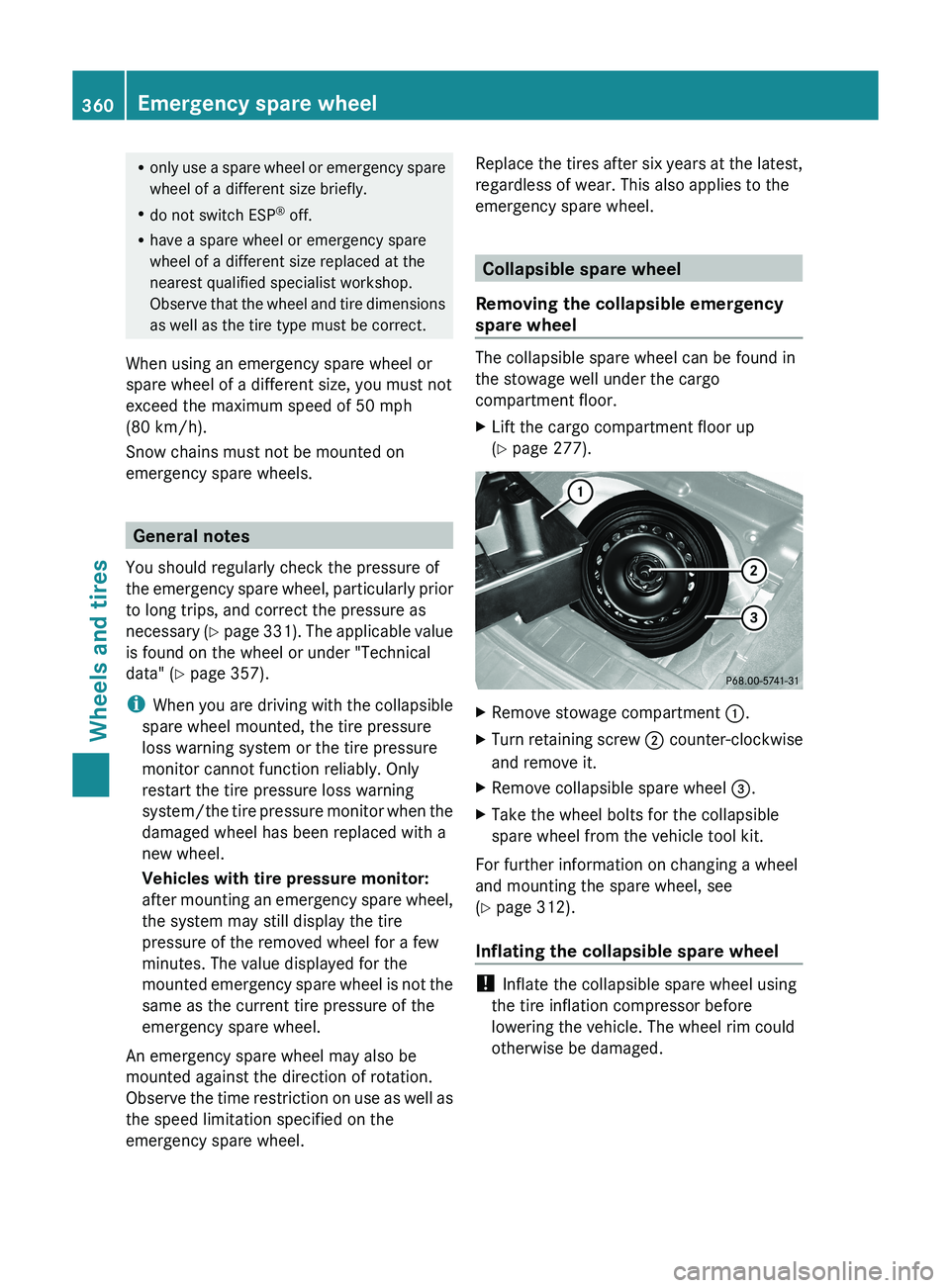
spare wheel The collapsible spare wheel can be found in
the stowage well under the cargo
compartment floor.
X
Lift the cargo compartment floor up
(Y page 277). X
Remove stowage compartment 0043.
X Turn retaining screw 0044 counter-clockwise
and remove it.
X Remove collapsible spare wheel 0087.
X Take the wheel bolts for the collapsible
spare wheel from the vehicle tool kit.
For further information on changing a wheel
and mounting the spare wheel, see
(Y page 312).
Inflating the collapsible spare wheel !
Inflate the collapsible spare wheel using
the tire inflation compressor before
lowering the vehicle. The wheel rim could
otherwise be damaged. 360
Emergency spare wheel
Wheels and tires
Page 363 of 380
X
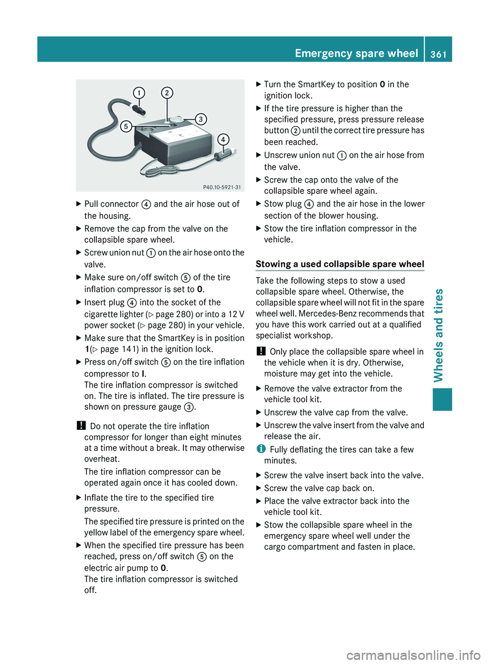
Pull connector 0085 and the air hose out of
the housing.
X Remove the cap from the valve on the
collapsible spare wheel.
X Screw union nut 0043 on the air hose onto the
valve.
X Make sure on/off switch 0083 of the tire
inflation compressor is set to 0.
X Insert plug 0085 into the socket of the
cigarette lighter (Y
page 280) or into a 12 V
power socket (Y page 280) in your vehicle.
X Make sure that the SmartKey is in position
1(Y page 141) in the ignition lock.
X Press on/off switch 0083 on the tire inflation
compressor to I
.
The tire inflation compressor is switched
on. The tire is inflated. The tire pressure is
shown on pressure gauge 0087.
! Do not operate the tire inflation
compressor for longer than eight minutes
at a time without
a
break. It may otherwise
overheat.
The tire inflation compressor can be
operated again once it has cooled down.
X Inflate the tire to the specified tire
pressure.
The specified tire pressure is
printed on the
yellow label of the emergency spare wheel.
X When the specified tire pressure has been
reached, press on/off switch 0083 on the
electric air pump to 0.
The tire inflation compressor is switched
off. X
Turn the SmartKey to position 0 in the
ignition lock.
X If the tire pressure is higher than the
specified pressure, press pressure release
button 0044 until the correct tire
pressure has
been reached.
X Unscrew union nut 0043 on the air hose
from
the valve.
X Screw the cap onto the valve of the
collapsible spare wheel again.
X Stow plug 0085 and the air hose in the lower
section of the blower housing.
X Stow the tire inflation compressor in the
vehicle.
Stowing a used collapsible spare wheel Take the following steps to stow a used
collapsible spare wheel. Otherwise, the
collapsible spare wheel will
not
fit in the spare
wheel well. Mercedes-Benz recommends that
you have this work carried out at a qualified
specialist workshop.
! Only place the collapsible spare wheel in
the vehicle when it is dry. Otherwise,
moisture may get into the vehicle.
X Remove the valve extractor from the
vehicle tool kit.
X Unscrew the valve cap from the valve.
X Unscrew the valve insert from the valve and
release the air.
i Fully deflating the tires can take a few
minutes.
X Screw the valve insert back into the valve.
X Screw the valve cap back on.
X Place the valve extractor back into the
vehicle tool kit.
X Stow the collapsible spare wheel in the
emergency spare wheel well under the
cargo compartment and fasten in place. Emergency spare wheel
361
Wheels and tires Z
Page 374 of 380
Windshield washer system and
headlamp cleaning system
Important safety notes G
WARNING
Windshield washer concentrate is highly
flammable. If it comes into contact with hot
engine components or the exhaust system it
could ignite. There is a risk of fire and injury.
Make sure that no windshield washer
concentrate is spilled next to the filler neck.
! Only use washer fluid that is suitable for
plastic lamp lenses, e.g. MB SummerFit or
MB WinterFit. Unsuitable washer fluid
could damage the plastic lenses of the
headlamps.
! Do not add distilled or
de-ionized water to
the washer fluid container. Otherwise, the
level sensor may be damaged.
! Only MB SummerFit and MB WinterFit
washer fluid should be mixed together. The
spray nozzles may otherwise become
blocked.
When handling washer fluid, observe the
important safety notes on service products
(Y page 365).
At temperatures above freezing:
X Fill the washer fluid reservoir with a mixture
of water and windshield washer fluid, e.g.
MB SummerFit.
X Add 1 part MB SummerFit to 100 parts
water.
At temperatures below freezing:
X Fill the washer fluid reservoir with a mixture
of water and washer fluid, e.g. MB
WinterFit. Adapt the mixing ratio to the outside
temperature.
R
Down to 14 ‡ (00FC10 †): mix 1 part MB
WinterFit with 2 parts water.
R Down to 00FC4 ‡ (
00FC20 †): mix 1 part MB
WinterFit with 1 part water.
R Down to 00FC20.2 ‡ (00FC29 †): mix 2 parts MB
WinterFit with 1 part water.
i Add windshield washer fluid, e.g. MB
SummerFit or MB WinterFit, to the washer
fluid all year round. Climate control system refrigerant
Important safety notes Type of refrigerant
Your vehicle's climate control
system
can be
filled with refrigerants R-134a or R-1234yf.
The instruction label about types of
refrigerants can be found on the radiator
cross member.
Refrigerant R-134a !
Only use refrigerant R-134a and PAG oil
(part number A0019890803) which has
been approved by Mercedes-Benz. The
approved R-134a PAG oil may
not be mixed
with other conventional PAG oils.
Otherwise, the climate control system may
be damaged.
Service work, such as topping-up refrigerant
or replacing components, may only be carried
out at a qualified specialist workshop. All
applicable regulations must be adhered to,
SAE standard J639 included.
Always have work on the climate control
system carried out at a qualified specialist
workshop.
Refrigerant R-1234yf !
Only use refrigerant R-1234yf and
PAG oil
(part number A0009890606) which has
been approved by Mercedes-Benz. The 372
Service products and filling capacities
Technical data