flat tire MERCEDES-BENZ GLK-CLASS SUV 2013 Owner's Manual
[x] Cancel search | Manufacturer: MERCEDES-BENZ, Model Year: 2013, Model line: GLK-CLASS SUV, Model: MERCEDES-BENZ GLK-CLASS SUV 2013Pages: 380, PDF Size: 19.54 MB
Page 339 of 380
pressure, the warning threshold for the
warning message is aligned to the reference
values taught-in. Restart the tire pressure
monitor after adjusting the pressure of the
cold tires (Y page 338). The current
pressures are saved as
new
reference values.
As a result, a warning message will appear if
the tire pressure drops significantly.
The tire pressure monitor does not warn you
of an incorrectly set tire pressure. Observe
the notes on the recommended tire pressure
(Y page 331).
The tire pressure monitor is not able to warn
you of a sudden loss of pressure, e.g. if the
tire is penetrated by a foreign object. In the
event of a sudden loss of pressure, bring the
vehicle to a halt by braking carefully. Avoid
abrupt steering maneuvers.
The tire pressure monitor has a yellow
warning lamp in the instrument cluster for
indicating pressure loss or a malfunction.
Whether the warning lamp flashes or lights up
indicates whether a tire pressure is too low or
the tire pressure monitor is malfunctioning:
R if the warning lamp is lit continuously, the
tire pressure on one or more tires is
significantly too low. The tire pressure
monitor is not malfunctioning.
R if the warning lamp flashes for around a
minute and then remains lit constantly, the
tire pressure monitor is malfunctioning. G
WARNING
Each tire, including the spare (if provided),
should be checked at least once a month
when cold and inflated to the pressure
recommended by the vehicle manufacturer
on the Tire and Loading Information placard
on the driver's door B-pillar or the tire
pressure label on the inside of the fuel filler
flap. If your vehicle has
tires of a different size
than the size indicated on the Tire and Loading
Information placard or the tire pressure label,
you should determine the proper tire pressure
for those tires.
As an added safety feature, your vehicle has
been equipped with a tire pressure monitoring system (TPMS) that illuminates a low tire
pressure telltale when one or more of your
tires are significantly underinflated.
Accordingly, when the low tire pressure
telltale illuminates, you should
stop
and check
your tires as soon as possible, and inflate
them to the proper pressure. Driving on a
significantly underinflated tire causes the tire
to overheat and can lead to tire failure.
Underinflation also reduces fuel efficiency
and tire tread life, and may affect the vehicle's
handling and stopping ability.
Please note that the TPMS is not a substitute
for proper tire maintenance, and it is the
driver's responsibility to maintain correct tire
pressure, even if underinflation has not
reached the level to trigger illumination of the
TPMS low tire pressure telltale.
Your vehicle has also been equipped with a
TPMS malfunction indicator to indicate if the
system is not operating properly. The TPMS
malfunction indicator is combined with the
low tire pressure telltale. When the system
detects a malfunction, the warning lamp will
flash for approximately a minute and then
remain continuously illuminated. This
sequence will be repeated every time the
vehicle is started as long as the malfunction
exists.
When the malfunction indicator is illuminated,
the system may not be able to detect or signal
low tire pressure as intended. TPMS
malfunctions may occur for a variety of
reasons, including the installation of
incompatible replacement or alternate tires
or wheels on the vehicle that prevent the
TPMS from functioning properly. Always
check the TPMS malfunction telltale after
replacing one or more tires or wheels on your
vehicle to ensure that the replacement or
alternate tires and wheels allow the TPMS to
continue to function properly.
i If the tire pressure monitor is
malfunctioning, it may take more than ten
minutes for the tire pressure warning lamp
to inform you of the malfunction by flashing Tire pressure
337
Wheels and tires Z
Page 347 of 380
reduce the braking distance on snow-covered
surfaces in comparison with summer tires.
Stopping distance, however, is still
considerably greater than when the road is
not covered with ice or snow. Take
appropriate care when driving.
!
Avoid wheelspin. This can lead
to damage
to the drive train. Temperature
G
WARNING
The temperature grade for this tire is
established for a tire that is properly inflated
and not overloaded. Excessive speed,
underinflation, or excessive loading, either
separately or in combination, can cause
excessive heat build-up and possible tire
failure.
The temperature grades are A (the highest),
B, and C. These represent the tire's
resistance to the generation of heat and its
ability to dissipate heat when tested under
controlled conditions on a specified indoor
laboratory test wheel. Sustained high
temperature can cause the material
of the tire
to degenerate and reduce tire life, and
excessive temperature can lead to sudden
tire failure. The grade C corresponds to a level
of performance which all passenger car tires
must meet under the Federal Motor Vehicle
Safety Standard No. 109. Grades B and A
represent higher levels of performance on the
laboratory test wheel than the minimum
required by law. Tire labeling
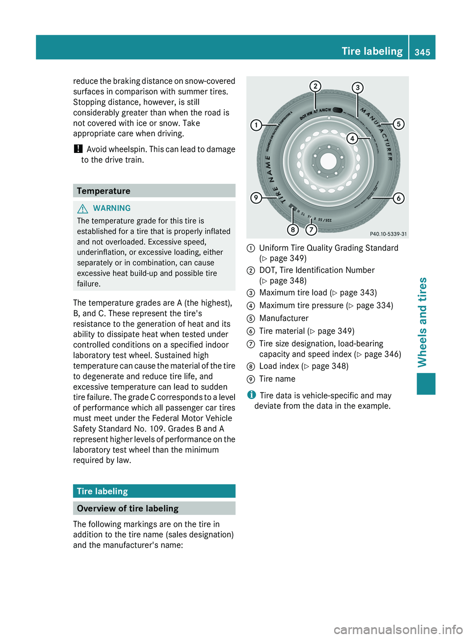
Overview of tire labeling
The following markings are on the tire in
addition to the tire name (sales designation)
and the manufacturer's name: 0043
Uniform Tire Quality Grading Standard
(Y page 349)
0044 DOT, Tire Identification Number
(Y page 348)
0087 Maximum tire load ( Y page 343)
0085 Maximum tire pressure (Y page 334)
0083 Manufacturer
0084 Tire material ( Y page 349)
006B Tire size designation, load-bearing
capacity and speed index (
Y page 346)
006C Load index ( Y page 348)
006D Tire name
i Tire data is vehicle-specific and may
deviate from the data in the example. Tire labeling
345
Wheels and tires Z
Page 354 of 380
Treadwear indicators
Narrow bars (tread wear bars) that are
distributed over the tire tread.
If the tire tread
is level with the bars, the wear limit of 00CD in
(1.6 mm) has been reached. Occupant distribution
The distribution of occupants in a vehicle at
their designated seating positions. Total load limit
Nominal load and luggage load plus 68 kg
(150 lbs)
multiplied by
the number of seats in
the vehicle. Changing a wheel
Flat tire
You can find
information on
what to do in the
event of a flat tire in the "Flat tire" section
(Y page 312).
Information on driving with MOExtended tires
in the event of a flat tire can be found under
"MOExtended tires (tires with run-flat
characteristics" (Y page 313). Rotating the wheels
G
WARNING
Interchanging the front and rear wheels may
severely impair the driving characteristics if
the wheels or tires have
different dimensions.
The wheel brakes or suspension components
may also be damaged. There is a risk of
accident.
Rotate front and rear wheels only if the wheels
and tires are of the same dimensions.
! On vehicles equipped with a tire pressure
monitor, electronic components are
located in the wheel. Tire-mounting tools should not be used
near the valve. This could damage the
electronic components.
Only have tires changed at a qualified
specialist workshop.
Always observe the instructions and safety
notes in the "Mounting a wheel" section
(Y page 353).
The wear patterns on the front and rear tires
differ, depending on the operating
conditions.
Rotate the wheels before a clear wear pattern
has formed on the tires. Front tires typically
wear more on the shoulders and the rear tires
in the center.
If your vehicle's tire configuration allows, you
can rotate the wheels according to the
intervals in the tire manufacturer's warranty
book in your vehicle documents. If no
warranty book is available, the tires should be
rotated every 3,000 to 6,000 miles (5,000 to
10,000 km), or earlier if tire wear requires. Do
not change the direction of wheel rotation.
Clean the contact surfaces of the wheel and
the brake disc thoroughly every time a wheel
is rotated. Check the tire pressures.
Information on changing tires and mounting
the spare wheel ( Y page 352). Direction of rotation
Tires with a specified direction of rotation
have additional benefits, e.g. if
there is a risk
of hydroplaning. You will only gain these
benefits if the correct direction of rotation is
maintained.
An arrow on the sidewall of the tire indicates
its correct direction of rotation. Storing wheels
Store wheels that are not
being used in a cool,
dry and preferably dark place. Protect the
tires from oil, grease, gasoline and diesel. 352
Changing a wheel
Wheels and tires
Page 356 of 380
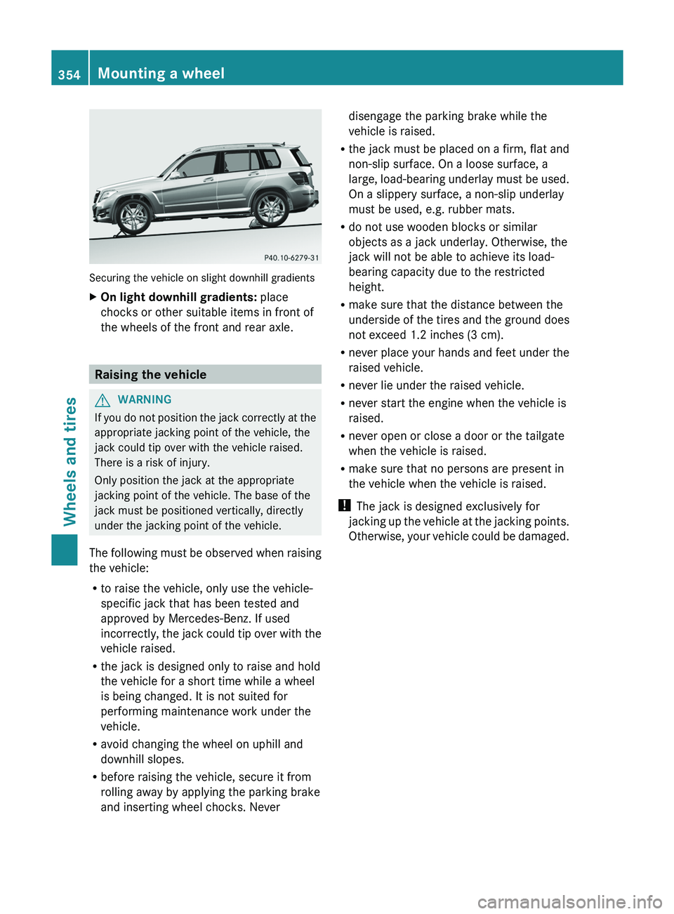
Securing the vehicle on slight downhill gradients
X
On light downhill gradients: place
chocks or other suitable items in front of
the wheels of the front and rear axle. Raising the vehicle
G
WARNING
If you do not position the jack correctly at the
appropriate jacking point of the vehicle, the
jack could tip over with the vehicle raised.
There is a risk of injury.
Only position the jack at the appropriate
jacking point of the vehicle. The base of the
jack must be positioned vertically, directly
under the jacking point of the vehicle.
The following must be observed
when raising
the vehicle:
R to raise the vehicle, only use the vehicle-
specific jack that has been tested and
approved by Mercedes-Benz. If used
incorrectly, the jack could tip over with the
vehicle raised.
R the jack is designed only to raise and hold
the vehicle for a short time while a wheel
is being changed. It is not suited for
performing maintenance work under the
vehicle.
R avoid changing the wheel on uphill and
downhill slopes.
R before raising the vehicle, secure it from
rolling away by applying the parking brake
and inserting wheel chocks. Never disengage the parking brake while the
vehicle is raised.
R the jack must be placed on a firm, flat and
non-slip surface. On a loose surface, a
large, load-bearing underlay
must be
used.
On a slippery surface, a non-slip underlay
must be used, e.g. rubber mats.
R do not use wooden blocks or similar
objects as a jack underlay. Otherwise, the
jack will not be able to achieve its load-
bearing capacity due to the restricted
height.
R make sure that the distance between the
underside of the tires and the ground does
not exceed 1.2 inches (3 cm).
R never place your hands and feet under the
raised vehicle.
R never lie under the raised vehicle.
R never start the engine when the vehicle is
raised.
R never open or close a door or the tailgate
when the vehicle is raised.
R make sure that no persons are present in
the vehicle when the vehicle is raised.
! The jack is designed exclusively for
jacking up the vehicle at the jacking points.
Otherwise, your vehicle could be damaged. 354
Mounting a wheel
Wheels and tires
Page 358 of 380
bolts to come loose. As a result, you could
lose a wheel while driving. There is a risk of
accident.
Never oil or grease wheel bolts. In the event
of damage to the
threads,
contact a qualified
specialist workshop immediately. Have the
damaged wheel bolts or hub threads
replaced/renewed. Do not continue driving. G
WARNING
If you tighten the wheel bolts or wheel nuts
when the vehicle is raised, the jack could tip
over. There is a risk of injury.
Only tighten the wheel bolts or wheel nuts
when the vehicle is on the ground.
Always pay attention to the instructions and
safety notes in the "Changing a wheel"
section ( Y page 352).
Only use wheel bolts that
have been designed
for the wheel and the vehicle. For safety
reasons, Mercedes-Benz recommends that
you only use wheel bolts which have been
approved for Mercedes-Benz vehicles and the
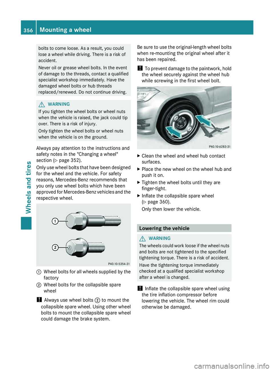
respective wheel. 0043
Wheel bolts for all wheels supplied by the
factory
0044 Wheel bolts for the collapsible spare
wheel
! Always use wheel bolts 0044 to mount the
collapsible spare wheel. Using other
wheel
bolts to mount the collapsible spare wheel
could damage the brake system. Be sure to use the original-length wheel bolts
when re-mounting the original wheel after it
has been repaired.
!
To prevent damage to
the
paintwork, hold
the wheel securely against the wheel hub
while screwing in the first wheel bolt. X
Clean the wheel and wheel hub contact
surfaces.
X Place the new wheel on the wheel hub and
push it on.
X Tighten the wheel bolts until they are
finger-tight.
X Inflate the collapsible spare wheel
(Y page 360).
Only then lower the vehicle. Lowering the vehicle
G
WARNING
The wheels could work loose if the wheel nuts
and bolts are not tightened to the specified
tightening torque. There is a risk of accident.
Have the tightening torque immediately
checked at a qualified specialist workshop
after a wheel is changed.
! Inflate the collapsible spare wheel using
the tire inflation compressor before
lowering the vehicle. The wheel rim could
otherwise be damaged. 356
Mounting a wheel
Wheels and tires
Page 359 of 380
X
Place the ratchet wrench onto the hexagon
nut of the jack so that the letters AB are
visible.
X Turn the ratchet wrench until the vehicle is
once again standing firmly on the ground.
X Place the jack to one side.
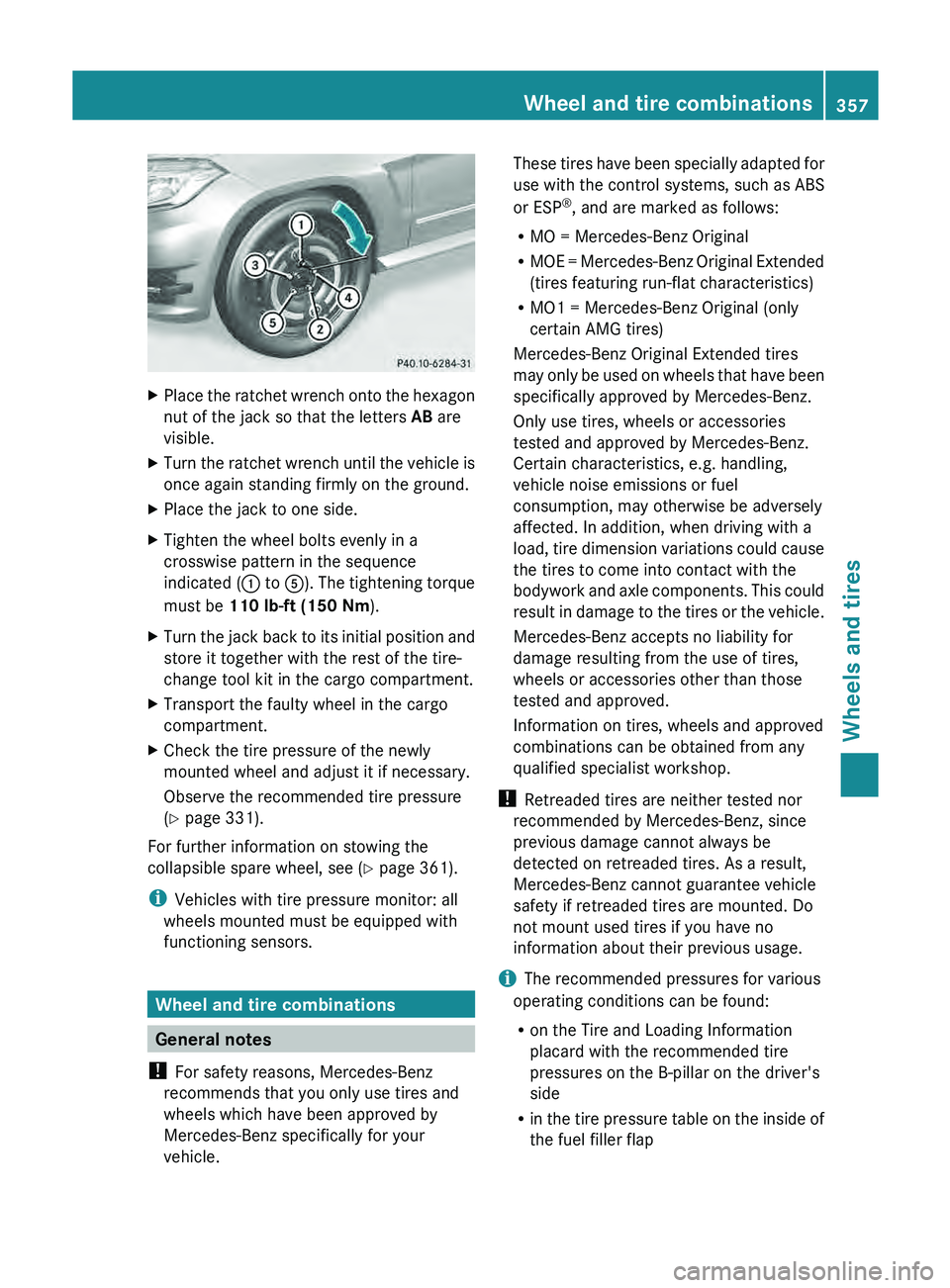
X Tighten the wheel bolts evenly in a
crosswise pattern in the sequence
indicated ( 0043 to 0083). The tightening
torque
must be 110 lb-ft (150 Nm).
X Turn the jack back to its initial position and
store it together with the rest of the tire-
change tool kit in the cargo compartment.
X Transport the faulty wheel in the cargo
compartment.
X Check the tire pressure of the newly
mounted wheel and adjust it if necessary.
Observe the recommended tire pressure
(Y page 331).
For further information on stowing the
collapsible spare wheel, see (Y page 361).
i Vehicles with tire pressure monitor: all
wheels mounted must be equipped with
functioning sensors. Wheel and tire combinations
General notes
! For safety reasons, Mercedes-Benz
recommends that you only use tires and
wheels which have been approved by
Mercedes-Benz specifically for your
vehicle. These tires have been specially adapted for
use with the control systems, such as ABS
or ESP
®
, and are marked as follows:
R MO = Mercedes-Benz Original
R MOE = Mercedes-Benz Original Extended
(tires featuring run-flat characteristics)
R MO1 = Mercedes-Benz Original (only
certain AMG tires)
Mercedes-Benz Original Extended tires
may
only be used on wheels that have been
specifically approved by Mercedes-Benz.
Only use tires, wheels or accessories
tested and approved by Mercedes-Benz.
Certain characteristics, e.g. handling,
vehicle noise emissions or fuel
consumption, may otherwise be adversely
affected. In addition, when driving with a
load, tire dimension variations could cause
the tires to come into contact with the
bodywork and axle components. This could
result in damage to the tires or the vehicle.
Mercedes-Benz accepts no liability for
damage resulting from the use of tires,
wheels or accessories other than those
tested and approved.
Information on tires, wheels and approved
combinations can be obtained from any
qualified specialist workshop.
! Retreaded tires are neither tested nor
recommended by Mercedes-Benz, since
previous damage cannot always be
detected on retreaded tires. As a result,
Mercedes-Benz cannot guarantee vehicle
safety if retreaded tires are mounted. Do
not mount used tires if you have no
information about their previous usage.
i The recommended pressures for various
operating conditions can be found:
R on the Tire and Loading Information
placard with the recommended tire
pressures on the B-pillar on the driver's
side
R in the tire pressure table on the inside of
the fuel filler flap Wheel and tire combinations
357
Wheels and tires Z
Page 361 of 380
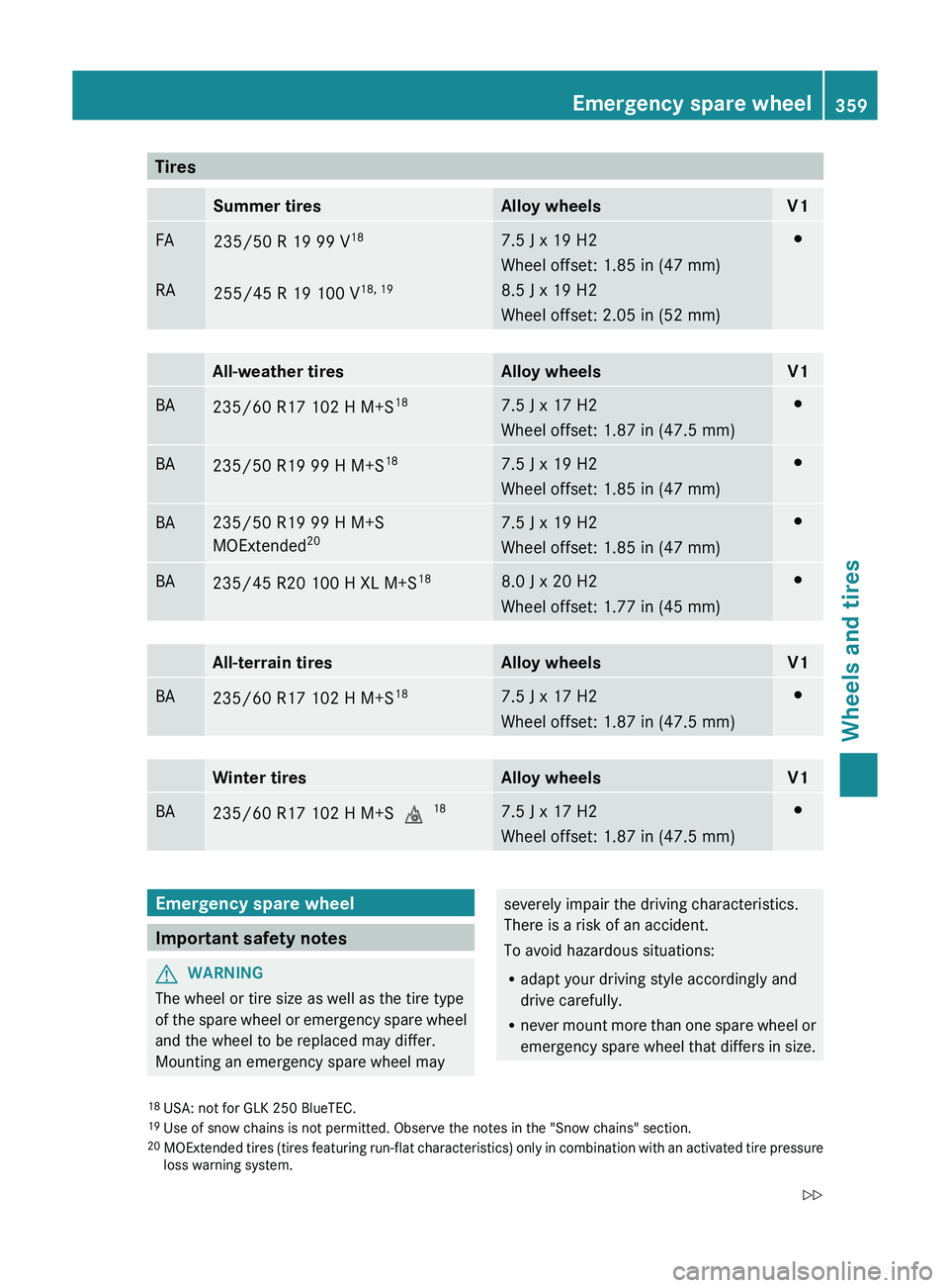
Tires
Summer tires Alloy wheels V1
FA
RA
235/50 R 19 99 V
18
255/45 R 19 100 V 18, 19 7.5 J x 19 H2
Wheel offset: 1.85 in (47 mm)
8.5 J x 19 H2
Wheel offset: 2.05 in (52 mm) 003B
All-weather tires Alloy wheels V1
BA
235/60 R17 102 H M+S
18 7.5 J x 17 H2
Wheel offset: 1.87 in (47.5 mm) 003B
BA
235/50 R19 99 H M+S
18 7.5 J x 19 H2
Wheel offset: 1.85 in (47 mm) 003B
BA 235/50 R19 99 H M+S
MOExtended
20 7.5 J x 19 H2
Wheel offset: 1.85 in (47 mm) 003B
BA
235/45 R20 100 H XL M+S
18 8.0 J x 20 H2
Wheel offset: 1.77 in (45 mm) 003B
All-terrain tires Alloy wheels V1
BA
235/60 R17 102 H M+S
18 7.5 J x 17 H2
Wheel offset: 1.87 in (47.5 mm) 003B
Winter tires Alloy wheels V1
BA
235/60 R17 102 H M+S
004D18 7.5 J x 17 H2
Wheel offset: 1.87 in (47.5 mm) 003B
Emergency spare wheel
Important safety notes
G
WARNING
The wheel or tire size as well as the tire type
of the spare wheel or
emergency spare wheel
and the wheel to be replaced may differ.
Mounting an emergency spare wheel may severely impair the driving characteristics.
There is a risk of an accident.
To avoid hazardous situations:
R
adapt your driving style accordingly and
drive carefully.
R never mount more than one
spare wheel or
emergency spare wheel that differs in size.
18 USA: not for GLK 250 BlueTEC.
19 Use of snow chains is not permitted. Observe the notes in the "Snow chains" section.
20 MOExtended tires (tires featuring run-flat
characteristics) only in combination with an activated tire pressure
loss warning system. Emergency spare wheel
359
Wheels and tires
Z
Page 362 of 380
R
only use a spare wheel or emergency spare
wheel of a different size briefly.
R do not switch ESP ®
off.
R have a spare wheel or emergency spare
wheel of a different size replaced at the
nearest qualified specialist workshop.
Observe that the wheel and tire dimensions
as well as the tire type must be correct.
When using an emergency spare wheel or
spare wheel of a different size, you must not
exceed the maximum speed of 50 mph
(80 km/h).
Snow chains must not be mounted on
emergency spare wheels. General notes
You should regularly check the pressure of
the emergency spare wheel, particularly
prior
to long trips, and correct the pressure as
necessary (Y page 331). The applicable value
is found on the wheel or under "Technical
data" ( Y page 357).
i When you are driving with the collapsible
spare wheel mounted, the tire pressure
loss warning system or the tire pressure
monitor cannot function reliably. Only
restart the tire pressure loss warning
system/the tire pressure monitor when the
damaged wheel has been replaced with a
new wheel.
Vehicles with tire pressure monitor:
after mounting an emergency spare wheel,
the system may still display the tire
pressure of the removed wheel for a few
minutes. The value displayed for the
mounted emergency spare wheel is not the
same as the current tire pressure of the
emergency spare wheel.
An emergency spare wheel may also be
mounted against the direction of rotation.
Observe the time restriction on use as well as
the speed limitation specified on the
emergency spare wheel. Replace the tires after six years at the latest,
regardless of wear. This also applies to the
emergency spare wheel.
Collapsible spare wheel
Removing the collapsible emergency
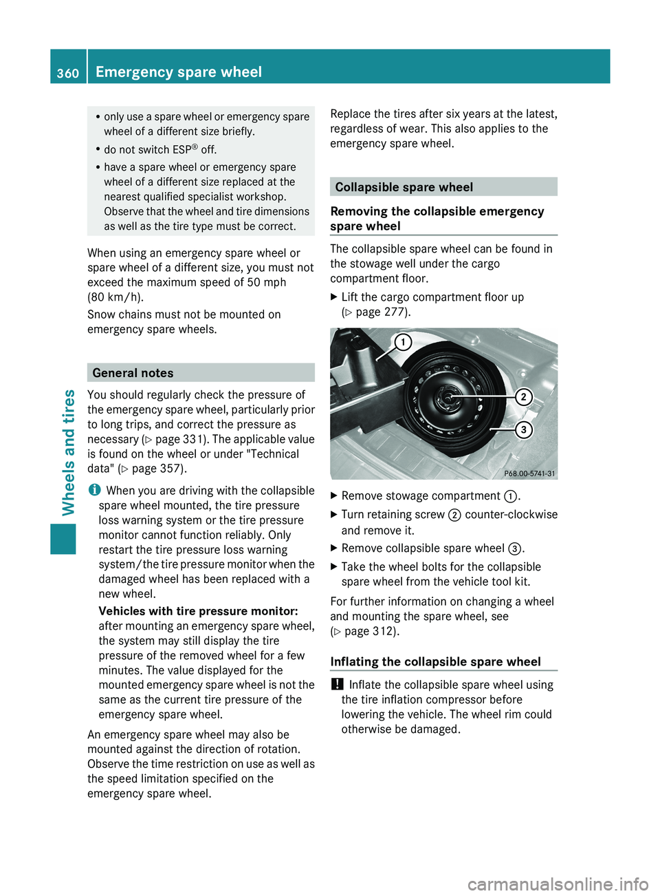
spare wheel The collapsible spare wheel can be found in
the stowage well under the cargo
compartment floor.
X
Lift the cargo compartment floor up
(Y page 277). X
Remove stowage compartment 0043.
X Turn retaining screw 0044 counter-clockwise
and remove it.
X Remove collapsible spare wheel 0087.
X Take the wheel bolts for the collapsible
spare wheel from the vehicle tool kit.
For further information on changing a wheel
and mounting the spare wheel, see
(Y page 312).
Inflating the collapsible spare wheel !
Inflate the collapsible spare wheel using
the tire inflation compressor before
lowering the vehicle. The wheel rim could
otherwise be damaged. 360
Emergency spare wheel
Wheels and tires
Page 363 of 380
X
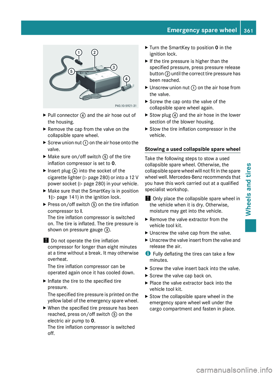
Pull connector 0085 and the air hose out of
the housing.
X Remove the cap from the valve on the
collapsible spare wheel.
X Screw union nut 0043 on the air hose onto the
valve.
X Make sure on/off switch 0083 of the tire
inflation compressor is set to 0.
X Insert plug 0085 into the socket of the
cigarette lighter (Y
page 280) or into a 12 V
power socket (Y page 280) in your vehicle.
X Make sure that the SmartKey is in position
1(Y page 141) in the ignition lock.
X Press on/off switch 0083 on the tire inflation
compressor to I
.
The tire inflation compressor is switched
on. The tire is inflated. The tire pressure is
shown on pressure gauge 0087.
! Do not operate the tire inflation
compressor for longer than eight minutes
at a time without
a
break. It may otherwise
overheat.
The tire inflation compressor can be
operated again once it has cooled down.
X Inflate the tire to the specified tire
pressure.
The specified tire pressure is
printed on the
yellow label of the emergency spare wheel.
X When the specified tire pressure has been
reached, press on/off switch 0083 on the
electric air pump to 0.
The tire inflation compressor is switched
off. X
Turn the SmartKey to position 0 in the
ignition lock.
X If the tire pressure is higher than the
specified pressure, press pressure release
button 0044 until the correct tire
pressure has
been reached.
X Unscrew union nut 0043 on the air hose
from
the valve.
X Screw the cap onto the valve of the
collapsible spare wheel again.
X Stow plug 0085 and the air hose in the lower
section of the blower housing.
X Stow the tire inflation compressor in the
vehicle.
Stowing a used collapsible spare wheel Take the following steps to stow a used
collapsible spare wheel. Otherwise, the
collapsible spare wheel will
not
fit in the spare
wheel well. Mercedes-Benz recommends that
you have this work carried out at a qualified
specialist workshop.
! Only place the collapsible spare wheel in
the vehicle when it is dry. Otherwise,
moisture may get into the vehicle.
X Remove the valve extractor from the
vehicle tool kit.
X Unscrew the valve cap from the valve.
X Unscrew the valve insert from the valve and
release the air.
i Fully deflating the tires can take a few
minutes.
X Screw the valve insert back into the valve.
X Screw the valve cap back on.
X Place the valve extractor back into the
vehicle tool kit.
X Stow the collapsible spare wheel in the
emergency spare wheel well under the
cargo compartment and fasten in place. Emergency spare wheel
361
Wheels and tires Z