clock MERCEDES-BENZ GLK350 4MATIC 2010 X204 Owner's Manual
[x] Cancel search | Manufacturer: MERCEDES-BENZ, Model Year: 2010, Model line: GLK350 4MATIC, Model: MERCEDES-BENZ GLK350 4MATIC 2010 X204Pages: 344, PDF Size: 8.45 MB
Page 8 of 344
Locking/unlocking from inside ........71
SmartKey ......................................... 66
Central locking/unlocking switch ..... 71
Certification label .............................. 328
Children in the vehicle
Air bags ........................................... 37
BabySmart™ air bag deactivation
system ............................................. 45
Child safety locks (rear doors) .........58
Child seat anchors – LATCH-type
(ISOFIX) ........................................... 57
Indicator lamp, front passenger
front air bag off (Canada only) .........45
Indicator lamp, front passenger
front air bag off (USA only) ..............42
Infant and child restraint systems .... 54
ISOFIX (Child seat anchors –
LATCH-type) ..................................... 57
OCS (Occupant Classification
System) ........................................... 42
Override switch ................................ 58
Safety notes ..................................... 53
Tether anchorage points ..................56
Top tether ........................................ 56
Child safety
see Children in the vehicle
Child seat anchors – LATCH-type
(ISOFIX) see Children in the vehicle
Chrome-plated exhaust tip,
cleaning .............................................. 257
Cigarette lighter ................................ 197
Clear button ....................................... 130
Climate control system .................... 177
Air conditioning ............................. 179
Air conditioning refrigerant ............336
Air distribution ............................... 181
Air recirculation mode ...................183
Air volume ..................................... 182
Automatic mode ............................ 179
Deactivating system ......................179
Front defroster .............................. 182
Maximum cooling MAX COOL ........182
Temperature .................................. 180
Clock ............................................ 29, 121
Coat hooks ......................................... 189
Cockpit ................................................. 27
Cold tire inflation pressure .............. 239Collapsible tire (spare wheel) .......... 333
Collapsible wheel chock ................... 261
COMAND system see separate COMAND system
operating instructions
Combination gauge ............................. 28
Combination switch ............................ 90
Compass ............................................ 199
Control system .................................. 110
Multifunction display .....................112
Multifunction steering wheel .........110
Resetting to factory settings ..........119
Control system menus ...................... 113
Audio ............................................. 115
Navi ............................................... 115
Service ........................................... 118
Settings ......................................... 119
Telephone ...................................... 117
Trip ................................................ 113
Control system submenus
Convenience .................................. 124
Instrument cluster .........................120
Lighting .......................................... 122
Time/Date ..................................... 121
Vehicle ........................................... 123
Convenience submenu
Easy-entry/exit feature .................. 124
Fold-in function for exterior rear
view mirrors ................................... 124
Coolant
Anticorrosion/antifreeze ...............338
Capacities ...................................... 334
Checking level ............................... 216
Messages in the multifunction
display ........................................... 279
Temperature gauge ........................ 109
Warning lamp ................................. 295
Coolant temperature gauge ............... 28
Corner-illuminating lamps .................. 91
Replacing bulbs ............................. 304
Cruise control .................................... 168
Activating ....................................... 169
Canceling ....................................... 169
Changing the set speed .................170
Last stored speed ..........................170
Lever .............................................. 169
Messages in the multifunction
display ........................................... 2676IndexX204_AKB; 3; 23, en-USd2ureepe,Version: 2.11.8.12009-07-16T19:16:58+02:00 - Seite 6
Page 31 of 344
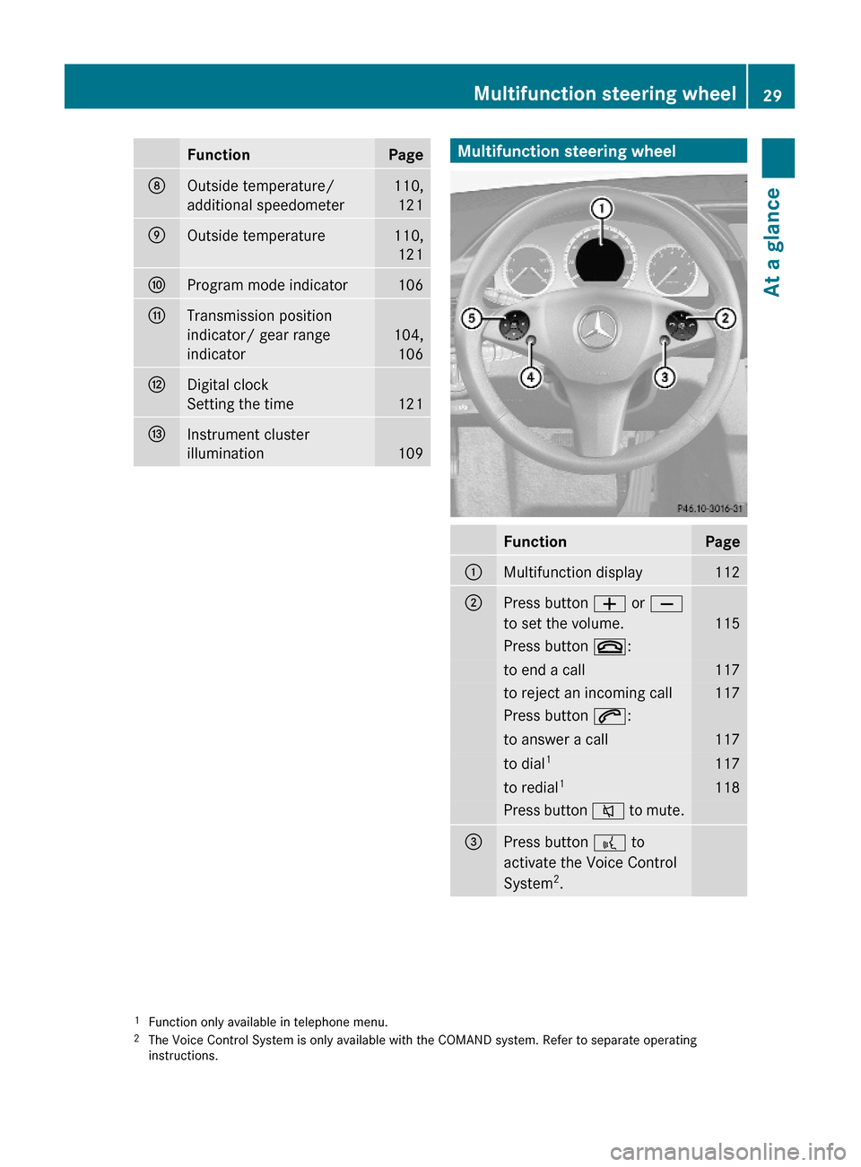
FunctionPageDOutside temperature/
additional speedometer
110,
121
EOutside temperature110,
121
FProgram mode indicator106GTransmission position
indicator/ gear range
indicator
104,
106
HDigital clock
Setting the time 121
IInstrument cluster
illumination109Multifunction steering wheelFunctionPage:Multifunction display112;Press button W or X
to set the volume.115
Press button ~:to end a call117to reject an incoming call117Press button 6:to answer a call117to dial1117to redial1118Press button 8 to mute.=Press button ? to
activate the Voice Control
System2.
1Function only available in telephone menu.2The Voice Control System is only available with the COMAND system. Refer to separate operatinginstructions.
Multifunction steering wheel29At a glanceX204_AKB; 3; 23, en-USd2ureepe,Version: 2.11.8.12009-07-16T19:16:58+02:00 - Seite 29Z
Page 111 of 344
If you must continue to drive, do so with added
caution. Contact an authorized Mercedes-
Benz Center as soon as possible.
The language setting for the multifunction
display can be changed with the audio system
(Y page 136) or with the COMAND system.
Vehicles with COMAND system: Refer to
separate operating instructions.
Activating the instrument cluster
The instrument cluster is activated when you
Ropen the driver’s door
Rswitch on the ignition
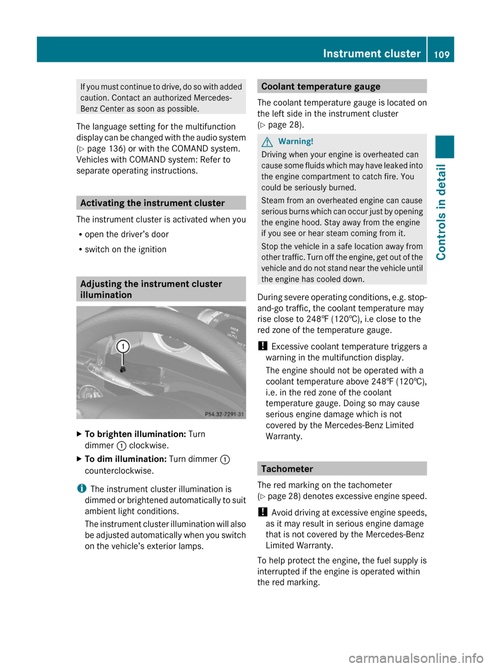
Adjusting the instrument cluster
illumination
XTo brighten illumination: Turn
dimmer : clockwise.
XTo dim illumination: Turn dimmer :
counterclockwise.
iThe instrument cluster illumination is
dimmed or brightened automatically to suit
ambient light conditions.
The instrument cluster illumination will also
be adjusted automatically when you switch
on the vehicle’s exterior lamps.
Coolant temperature gauge
The coolant temperature gauge is located on
the left side in the instrument cluster
(Y page 28).
GWarning!
Driving when your engine is overheated can
cause some fluids which may have leaked into
the engine compartment to catch fire. You
could be seriously burned.
Steam from an overheated engine can cause
serious burns which can occur just by opening
the engine hood. Stay away from the engine
if you see or hear steam coming from it.
Stop the vehicle in a safe location away from
other traffic. Turn off the engine, get out of the
vehicle and do not stand near the vehicle until
the engine has cooled down.
During severe operating conditions, e.g. stop-
and-go traffic, the coolant temperature may
rise close to 248‡ (120†), i.e close to the
red zone of the temperature gauge.
! Excessive coolant temperature triggers a
warning in the multifunction display.
The engine should not be operated with a
coolant temperature above 248‡ (120†),
i.e. in the red zone of the coolant
temperature gauge. Doing so may cause
serious engine damage which is not
covered by the Mercedes-Benz Limited
Warranty.
Tachometer
The red marking on the tachometer
(Y page 28) denotes excessive engine speed.
! Avoid driving at excessive engine speeds,
as it may result in serious engine damage
that is not covered by the Mercedes-Benz
Limited Warranty.
To help protect the engine, the fuel supply is
interrupted if the engine is operated within
the red marking.
Instrument cluster109Controls in detailX204_AKB; 3; 23, en-USd2ureepe,Version: 2.11.8.12009-07-16T19:16:58+02:00 - Seite 109Z
Page 114 of 344
XTo go to the next higher menu level:
Press button %.
XTo select the standard display: Press
button % repeatedly until the standard
display featuring the odometer and
speedometer appears.
or
XPress and hold button % until the
standard display featuring the trip
odometer and the main odometer appears.
XTo confirm selection: Press button a.XTo confirm display message: Press
button a or %.
The control system saves certain display
messages. Calling up display messages
(Y page 118).
For information about warning and
malfunction messages appearing in the
multifunction display (Y page 262).
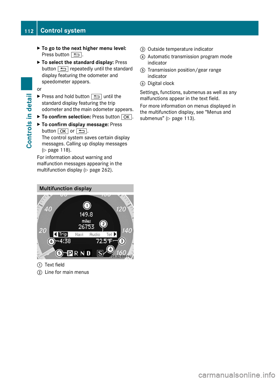
Multifunction display
:Text field;Line for main menus=Outside temperature indicator?Automatic transmission program mode
indicator
ATransmission position/gear range
indicator
BDigital clock
Settings, functions, submenus as well as any
malfunctions appear in the text field.
For more information on menus displayed in
the multifunction display, see “Menus and
submenus” (Y page 113).
112Control systemControls in detail
X204_AKB; 3; 23, en-USd2ureepe,Version: 2.11.8.12009-07-16T19:16:58+02:00 - Seite 112
Page 182 of 344
more quickly. Window fogging may impair
visibility and endanger you and others.
XSet the desired temperature
(Y page 180).
XActivating: Press button Ã.
The indicator lamp in the button comes on.
The air volume and air distribution are
adjusted automatically.
XDeactivating: Press button I, K or
_.
The indicator lamp in button à goes out.
The automatic operation of air volume and
air distribution switches off. The symbols of
air distribution or air volume appear in
display G (Y page 177).
XAdjust air distribution (Y page 181).XAdjust air volume (Y page 182).
Setting temperature
You can adjust the air temperature on each
side of the passenger compartment. You
should raise or lower the temperature setting
in small increments, preferably starting at
72‡ (22†).
You can adjust the air temperature on each
side of the passenger compartment. You
should raise or lower the temperature setting
in small increments, preferably starting at
72‡ (22†).
XIncreasing/decreasing: Turn
temperature controls : and B
(Y page 177) slightly clockwise or
counterclockwise.
Adjusting air vents
GWarning!
When operating the climate control, the air
that enters the passenger compartment
through the air vents can be very hot or very
cold (depending on the set temperature). This
may cause burns or frostbite to unprotected
skin in the immediate area of the air vents.
Always keep sufficient distance between
unprotected parts of the body and the air
vents. If necessary, use the air distribution
adjustment to direct the air to air vents in the
vehicle interior that are not in the immediate
area of unprotected skin.
For best possible performance of the climate
control:
XKeep the air intake grille in front of the
windshield free of snow, leaves, sticks, and
any other debris.
XAlways keep all air vents and grilles in the
passenger compartment free from
obstruction.
iFor draft-free ventilation, move the
adjustable center and side air vents to the
middle position.
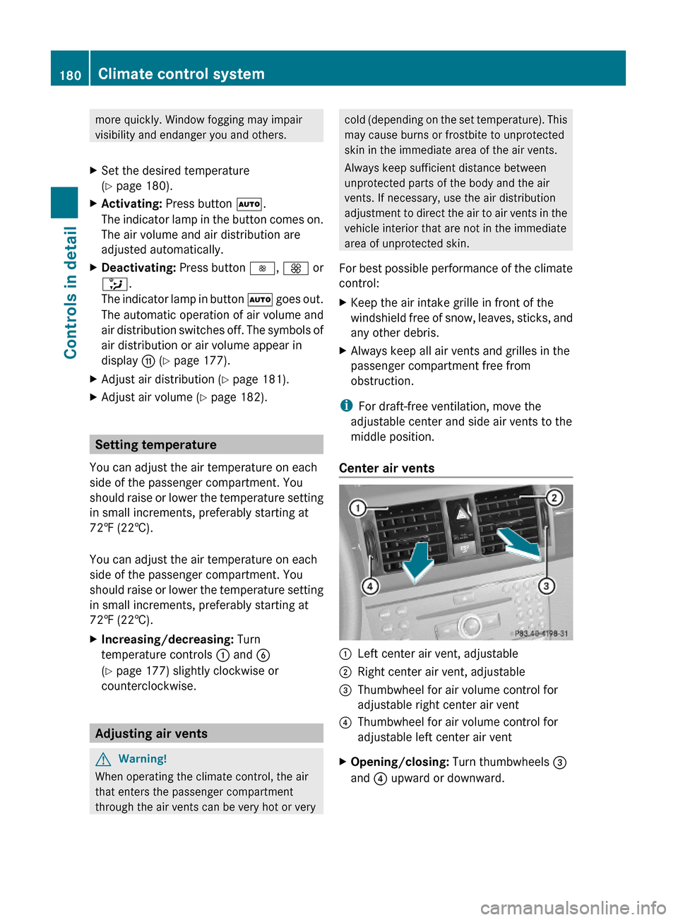
Center air vents
:Left center air vent, adjustable;Right center air vent, adjustable=Thumbwheel for air volume control for
adjustable right center air vent
?Thumbwheel for air volume control for
adjustable left center air vent
XOpening/closing: Turn thumbwheels =
and ? upward or downward.
180Climate control systemControls in detail
X204_AKB; 3; 23, en-USd2ureepe,Version: 2.11.8.12009-07-16T19:16:58+02:00 - Seite 180
Page 183 of 344
Side air vents
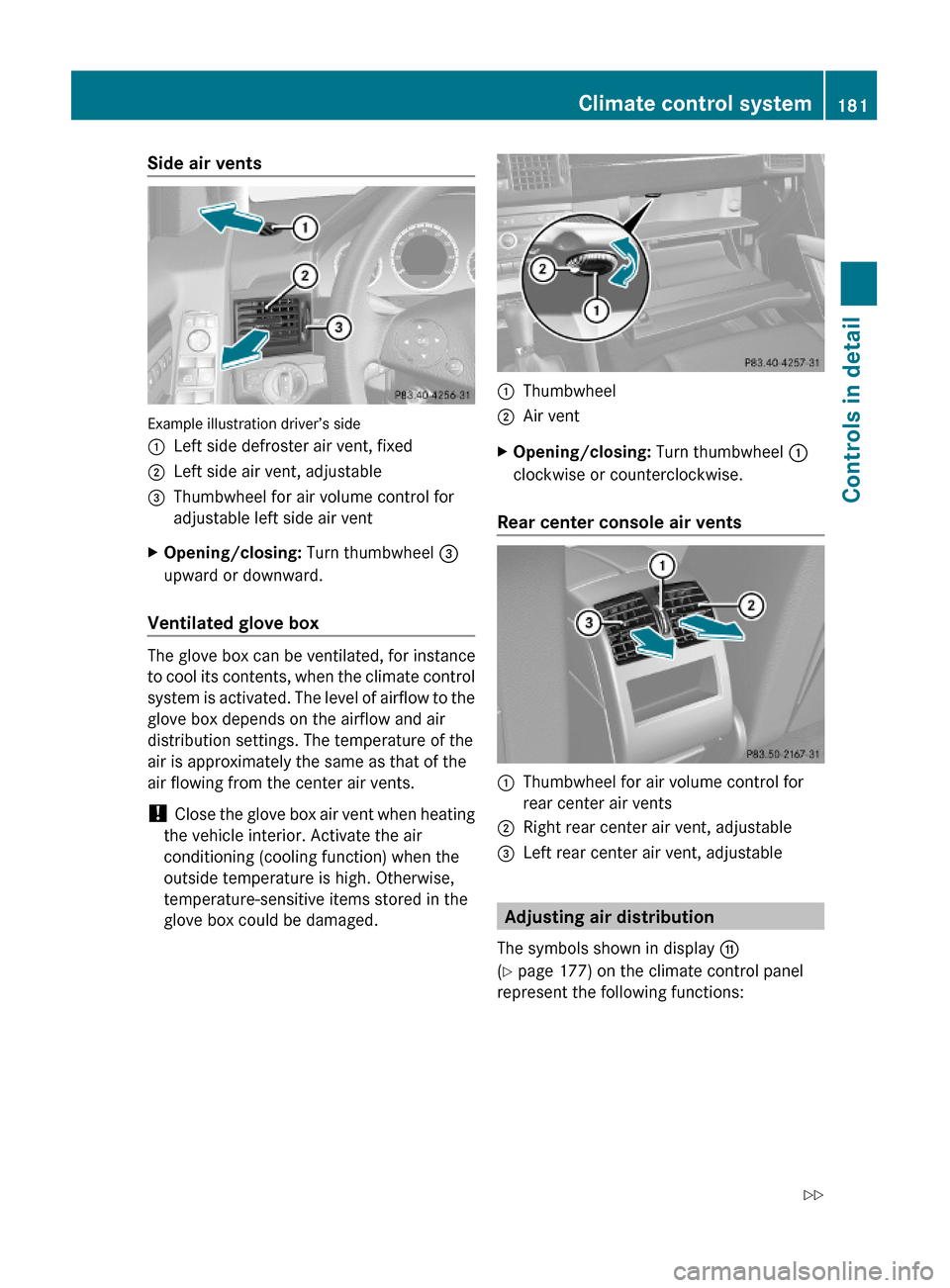
Example illustration driver’s side
:Left side defroster air vent, fixed;Left side air vent, adjustable=Thumbwheel for air volume control for
adjustable left side air vent
XOpening/closing: Turn thumbwheel =
upward or downward.
Ventilated glove box
The glove box can be ventilated, for instance
to cool its contents, when the climate control
system is activated. The level of airflow to the
glove box depends on the airflow and air
distribution settings. The temperature of the
air is approximately the same as that of the
air flowing from the center air vents.
! Close the glove box air vent when heating
the vehicle interior. Activate the air
conditioning (cooling function) when the
outside temperature is high. Otherwise,
temperature-sensitive items stored in the
glove box could be damaged.
:Thumbwheel;Air ventXOpening/closing: Turn thumbwheel :
clockwise or counterclockwise.
Rear center console air vents
:Thumbwheel for air volume control for
rear center air vents
;Right rear center air vent, adjustable=Left rear center air vent, adjustable
Adjusting air distribution
The symbols shown in display G
(Y page 177) on the climate control panel
represent the following functions:
Climate control system181Controls in detailX204_AKB; 3; 23, en-USd2ureepe,Version: 2.11.8.12009-07-16T19:16:58+02:00 - Seite 181Z
Page 215 of 344
Any noticeable irregularities in engine
operation should be repaired promptly.
Otherwise, excessive unburned fuel may
reach the catalytic converter, causing it to
overheat and potentially start a fire.
i Only use premium unleaded gasoline with
a minimum Posted Octane Rating of 91
(average of 96 RON/86 MON).
Information on gasoline quality can
normally be found on the fuel pump. Please
contact gas station personnel in case
labels on the pump cannot be found.
Locking/unlocking the vehicle with the
SmartKey or KEYLESS-GO automatically
locks/unlocks the fuel filler flap.
iIn case the central locking system does
not release the fuel filler flap, see “Fuel filler
flap” (Y page 301).
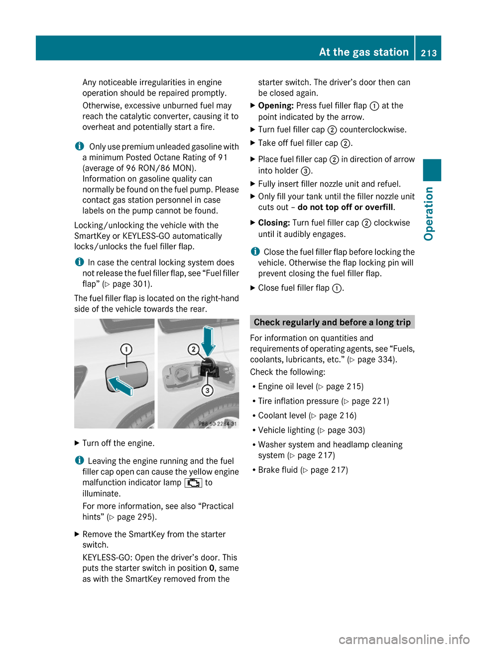
The fuel filler flap is located on the right-hand
side of the vehicle towards the rear.
XTurn off the engine.
iLeaving the engine running and the fuel
filler cap open can cause the yellow engine
malfunction indicator lamp ; to
illuminate.
For more information, see also “Practical
hints” (Y page 295).
XRemove the SmartKey from the starter
switch.
KEYLESS-GO: Open the driver’s door. This
puts the starter switch in position 0, same
as with the SmartKey removed from the
starter switch. The driver’s door then can
be closed again.
XOpening: Press fuel filler flap : at the
point indicated by the arrow.
XTurn fuel filler cap ; counterclockwise.XTake off fuel filler cap ;.XPlace fuel filler cap ; in direction of arrow
into holder =.
XFully insert filler nozzle unit and refuel.XOnly fill your tank until the filler nozzle unit
cuts out – do not top off or overfill.
XClosing: Turn fuel filler cap ; clockwise
until it audibly engages.
iClose the fuel filler flap before locking the
vehicle. Otherwise the flap locking pin will
prevent closing the fuel filler flap.
XClose fuel filler flap :.
Check regularly and before a long trip
For information on quantities and
requirements of operating agents, see “Fuels,
coolants, lubricants, etc.” (Y page 334).
Check the following:
REngine oil level (Y page 215)
RTire inflation pressure (Y page 221)
RCoolant level (Y page 216)
RVehicle lighting (Y page 303)
RWasher system and headlamp cleaning
system (Y page 217)
RBrake fluid (Y page 217)
At the gas station213OperationX204_AKB; 3; 23, en-USd2ureepe,Version: 2.11.8.12009-07-16T19:16:58+02:00 - Seite 213Z
Page 218 of 344
Adding engine oil
! Only use approved engine oils and oil
filters required for vehicles with
Maintenance System. For a listing of
approved engine oils and oil filters, contact
an authorized Mercedes-Benz Center or
visit www.mbusa.com (USA only).
The following will result in engine or
emission control system damage not
covered by the Mercedes-Benz Limited
Warranty:
RUsing engine oils and oil filters of
specification other than those expressly
required for the Maintenance System.
RChanging of oil and oil filter at change
intervals longer than those called for by
the Maintenance System.
RUsing any oil additives.
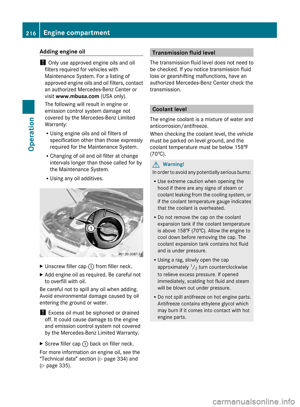
XUnscrew filler cap : from filler neck.XAdd engine oil as required. Be careful not
to overfill with oil.
Be careful not to spill any oil when adding.
Avoid environmental damage caused by oil
entering the ground or water.
! Excess oil must be siphoned or drained
off. It could cause damage to the engine
and emission control system not covered
by the Mercedes-Benz Limited Warranty.
XScrew filler cap : back on filler neck.
For more information on engine oil, see the
“Technical data” section (Y page 334) and
(Y page 335).
Transmission fluid level
The transmission fluid level does not need to
be checked. If you notice transmission fluid
loss or gearshifting malfunctions, have an
authorized Mercedes-Benz Center check the
transmission.
Coolant level
The engine coolant is a mixture of water and
anticorrosion/antifreeze.
When checking the coolant level, the vehicle
must be parked on level ground, and the
coolant temperature must be below 158‡
(70†).
GWarning!
In order to avoid any potentially serious burns:
RUse extreme caution when opening the
hood if there are any signs of steam or
coolant leaking from the cooling system, or
if the coolant temperature gauge indicates
that the coolant is overheated.
RDo not remove the cap on the coolant
expansion tank if the coolant temperature
is above 158‡ (70†). Allow the engine to
cool down before removing the cap. The
coolant expansion tank contains hot fluid
and is under pressure.
RUsing a rag, slowly open the cap
approximately 1/2 turn counterclockwise
to relieve excess pressure. If opened
immediately, scalding hot fluid and steam
will be blown out under pressure.
RDo not spill antifreeze on hot engine parts.
Antifreeze contains ethylene glycol which
may burn if it comes into contact with hot
engine parts.
216Engine compartmentOperation
X204_AKB; 3; 23, en-USd2ureepe,Version: 2.11.8.12009-07-16T19:16:58+02:00 - Seite 216
Page 219 of 344
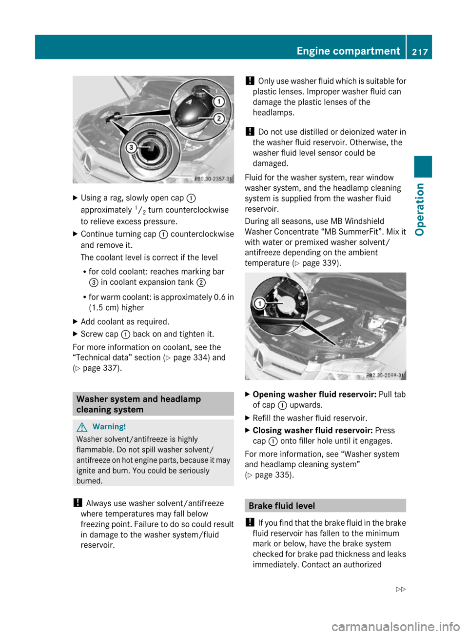
XUsing a rag, slowly open cap :
approximately 1/2 turn counterclockwise
to relieve excess pressure.
XContinue turning cap : counterclockwise
and remove it.
The coolant level is correct if the level
Rfor cold coolant: reaches marking bar
= in coolant expansion tank ;
Rfor warm coolant: is approximately 0.6 in
(1.5 cm) higher
XAdd coolant as required.XScrew cap : back on and tighten it.
For more information on coolant, see the
“Technical data” section (Y page 334) and
(Y page 337).
Washer system and headlamp
cleaning system
GWarning!
Washer solvent/antifreeze is highly
flammable. Do not spill washer solvent/
antifreeze on hot engine parts, because it may
ignite and burn. You could be seriously
burned.
! Always use washer solvent/antifreeze
where temperatures may fall below
freezing point. Failure to do so could result
in damage to the washer system/fluid
reservoir.
! Only use washer fluid which is suitable for
plastic lenses. Improper washer fluid can
damage the plastic lenses of the
headlamps.
! Do not use distilled or deionized water in
the washer fluid reservoir. Otherwise, the
washer fluid level sensor could be
damaged.
Fluid for the washer system, rear window
washer system, and the headlamp cleaning
system is supplied from the washer fluid
reservoir.
During all seasons, use MB Windshield
Washer Concentrate “MB SummerFit”. Mix it
with water or premixed washer solvent/
antifreeze depending on the ambient
temperature (Y page 339).
XOpening washer fluid reservoir: Pull tab
of cap : upwards.
XRefill the washer fluid reservoir.XClosing washer fluid reservoir: Press
cap : onto filler hole until it engages.
For more information, see “Washer system
and headlamp cleaning system”
(Y page 335).
Brake fluid level
! If you find that the brake fluid in the brake
fluid reservoir has fallen to the minimum
mark or below, have the brake system
checked for brake pad thickness and leaks
immediately. Contact an authorized
Engine compartment217OperationX204_AKB; 3; 23, en-USd2ureepe,Version: 2.11.8.12009-07-16T19:16:58+02:00 - Seite 217Z
Page 264 of 344
XAttach reversible ratchet ; to jack : in
such a way that the word UP can be seen.
Before placing the jack and the reversible
ratchet back into the vehicle tool kit:
XFully collapse the jack (storage position).XRemove the reversible ratchet.
Spare wheel
GObserve Safety notes, see page 312.
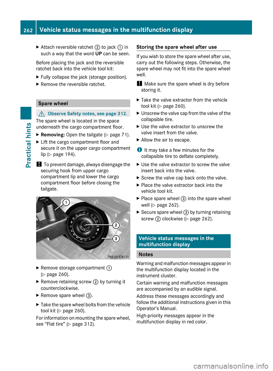
The spare wheel is located in the space
underneath the cargo compartment floor.
XRemoving: Open the tailgate (Y page 71).XLift the cargo compartment floor and
secure it on the upper cargo compartment
lip (Y page 194).
! To prevent damage, always disengage the
securing hook from upper cargo
compartment lip and lower the cargo
compartment floor before closing the
tailgate.
XRemove storage compartment :
(Y page 260).
XRemove retaining screw ; by turning it
counterclockwise.
XRemove spare wheel =.XTake the spare wheel bolts from the vehicle
tool kit (Y page 260).
For information on mounting the spare wheel,
see “Flat tire” (Y page 312).
Storing the spare wheel after use
If you wish to store the spare wheel after use,
carry out the following steps. Otherwise, the
spare wheel may not fit into the spare wheel
well.
! Make sure the spare wheel is dry before
storing it.
XTake the valve extractor from the vehicle
tool kit (Y page 260).
XUnscrew the valve cap from the valve of the
collapsible tire.
XUse the valve extractor to unscrew the
valve insert from the valve.
XAllow the air to escape.
iIt may take a few minutes for the
collapsible tire to deflate completely.
XUse the valve extractor to screw the valve
insert back into the valve.
XScrew the valve cap back onto the valve.XPlace the valve extractor back into the
vehicle tool kit.
XPlace spare wheel = into the spare wheel
well (Y page 262).
XSecure spare wheel = by turning retaining
screw ; clockwise (Y page 262).
Vehicle status messages in the
multifunction display
Notes
Warning and malfunction messages appear in
the multifunction display located in the
instrument cluster.
Certain warning and malfunction messages
are accompanied by an audible signal.
Address these messages accordingly and
follow the additional instructions given in this
Operator’s Manual.
High-priority messages appear in the
multifunction display in red color.
262Vehicle status messages in the multifunction displayPractical hints
X204_AKB; 3; 23, en-USd2ureepe,Version: 2.11.8.12009-07-16T19:16:58+02:00 - Seite 262