set clock MERCEDES-BENZ GLK350 4MATIC 2010 X204 Owner's Manual
[x] Cancel search | Manufacturer: MERCEDES-BENZ, Model Year: 2010, Model line: GLK350 4MATIC, Model: MERCEDES-BENZ GLK350 4MATIC 2010 X204Pages: 344, PDF Size: 8.45 MB
Page 8 of 344
Locking/unlocking from inside ........71
SmartKey ......................................... 66
Central locking/unlocking switch ..... 71
Certification label .............................. 328
Children in the vehicle
Air bags ........................................... 37
BabySmart™ air bag deactivation
system ............................................. 45
Child safety locks (rear doors) .........58
Child seat anchors – LATCH-type
(ISOFIX) ........................................... 57
Indicator lamp, front passenger
front air bag off (Canada only) .........45
Indicator lamp, front passenger
front air bag off (USA only) ..............42
Infant and child restraint systems .... 54
ISOFIX (Child seat anchors –
LATCH-type) ..................................... 57
OCS (Occupant Classification
System) ........................................... 42
Override switch ................................ 58
Safety notes ..................................... 53
Tether anchorage points ..................56
Top tether ........................................ 56
Child safety
see Children in the vehicle
Child seat anchors – LATCH-type
(ISOFIX) see Children in the vehicle
Chrome-plated exhaust tip,
cleaning .............................................. 257
Cigarette lighter ................................ 197
Clear button ....................................... 130
Climate control system .................... 177
Air conditioning ............................. 179
Air conditioning refrigerant ............336
Air distribution ............................... 181
Air recirculation mode ...................183
Air volume ..................................... 182
Automatic mode ............................ 179
Deactivating system ......................179
Front defroster .............................. 182
Maximum cooling MAX COOL ........182
Temperature .................................. 180
Clock ............................................ 29, 121
Coat hooks ......................................... 189
Cockpit ................................................. 27
Cold tire inflation pressure .............. 239Collapsible tire (spare wheel) .......... 333
Collapsible wheel chock ................... 261
COMAND system see separate COMAND system
operating instructions
Combination gauge ............................. 28
Combination switch ............................ 90
Compass ............................................ 199
Control system .................................. 110
Multifunction display .....................112
Multifunction steering wheel .........110
Resetting to factory settings ..........119
Control system menus ...................... 113
Audio ............................................. 115
Navi ............................................... 115
Service ........................................... 118
Settings ......................................... 119
Telephone ...................................... 117
Trip ................................................ 113
Control system submenus
Convenience .................................. 124
Instrument cluster .........................120
Lighting .......................................... 122
Time/Date ..................................... 121
Vehicle ........................................... 123
Convenience submenu
Easy-entry/exit feature .................. 124
Fold-in function for exterior rear
view mirrors ................................... 124
Coolant
Anticorrosion/antifreeze ...............338
Capacities ...................................... 334
Checking level ............................... 216
Messages in the multifunction
display ........................................... 279
Temperature gauge ........................ 109
Warning lamp ................................. 295
Coolant temperature gauge ............... 28
Corner-illuminating lamps .................. 91
Replacing bulbs ............................. 304
Cruise control .................................... 168
Activating ....................................... 169
Canceling ....................................... 169
Changing the set speed .................170
Last stored speed ..........................170
Lever .............................................. 169
Messages in the multifunction
display ........................................... 2676IndexX204_AKB; 3; 23, en-USd2ureepe,Version: 2.11.8.12009-07-16T19:16:58+02:00 - Seite 6
Page 31 of 344
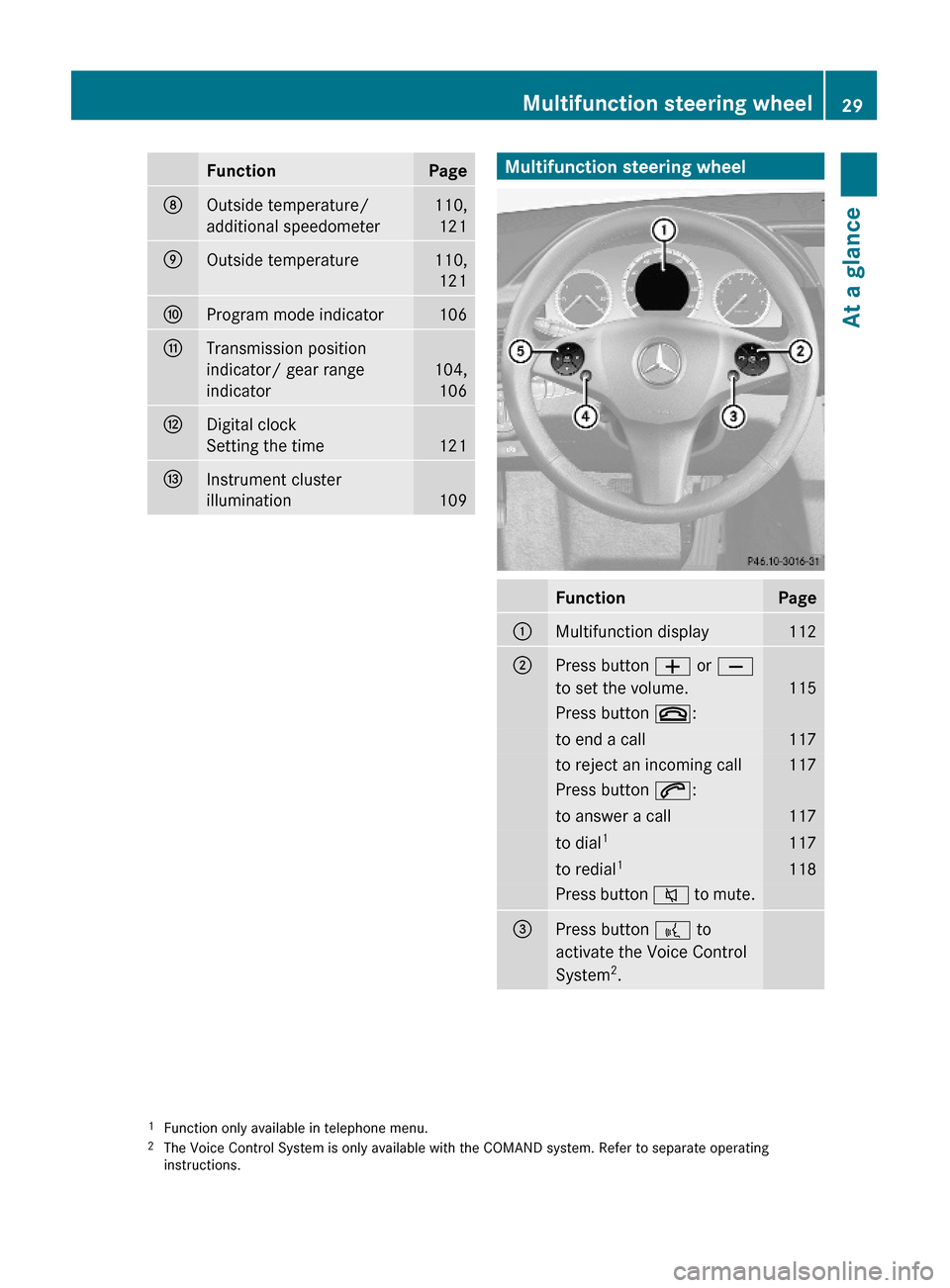
FunctionPageDOutside temperature/
additional speedometer
110,
121
EOutside temperature110,
121
FProgram mode indicator106GTransmission position
indicator/ gear range
indicator
104,
106
HDigital clock
Setting the time 121
IInstrument cluster
illumination109Multifunction steering wheelFunctionPage:Multifunction display112;Press button W or X
to set the volume.115
Press button ~:to end a call117to reject an incoming call117Press button 6:to answer a call117to dial1117to redial1118Press button 8 to mute.=Press button ? to
activate the Voice Control
System2.
1Function only available in telephone menu.2The Voice Control System is only available with the COMAND system. Refer to separate operatinginstructions.
Multifunction steering wheel29At a glanceX204_AKB; 3; 23, en-USd2ureepe,Version: 2.11.8.12009-07-16T19:16:58+02:00 - Seite 29Z
Page 111 of 344
If you must continue to drive, do so with added
caution. Contact an authorized Mercedes-
Benz Center as soon as possible.
The language setting for the multifunction
display can be changed with the audio system
(Y page 136) or with the COMAND system.
Vehicles with COMAND system: Refer to
separate operating instructions.
Activating the instrument cluster
The instrument cluster is activated when you
Ropen the driver’s door
Rswitch on the ignition
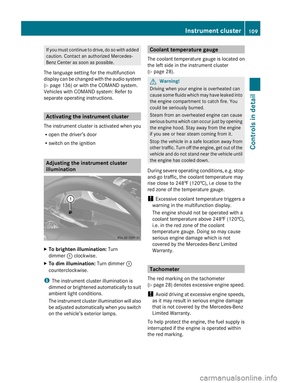
Adjusting the instrument cluster
illumination
XTo brighten illumination: Turn
dimmer : clockwise.
XTo dim illumination: Turn dimmer :
counterclockwise.
iThe instrument cluster illumination is
dimmed or brightened automatically to suit
ambient light conditions.
The instrument cluster illumination will also
be adjusted automatically when you switch
on the vehicle’s exterior lamps.
Coolant temperature gauge
The coolant temperature gauge is located on
the left side in the instrument cluster
(Y page 28).
GWarning!
Driving when your engine is overheated can
cause some fluids which may have leaked into
the engine compartment to catch fire. You
could be seriously burned.
Steam from an overheated engine can cause
serious burns which can occur just by opening
the engine hood. Stay away from the engine
if you see or hear steam coming from it.
Stop the vehicle in a safe location away from
other traffic. Turn off the engine, get out of the
vehicle and do not stand near the vehicle until
the engine has cooled down.
During severe operating conditions, e.g. stop-
and-go traffic, the coolant temperature may
rise close to 248‡ (120†), i.e close to the
red zone of the temperature gauge.
! Excessive coolant temperature triggers a
warning in the multifunction display.
The engine should not be operated with a
coolant temperature above 248‡ (120†),
i.e. in the red zone of the coolant
temperature gauge. Doing so may cause
serious engine damage which is not
covered by the Mercedes-Benz Limited
Warranty.
Tachometer
The red marking on the tachometer
(Y page 28) denotes excessive engine speed.
! Avoid driving at excessive engine speeds,
as it may result in serious engine damage
that is not covered by the Mercedes-Benz
Limited Warranty.
To help protect the engine, the fuel supply is
interrupted if the engine is operated within
the red marking.
Instrument cluster109Controls in detailX204_AKB; 3; 23, en-USd2ureepe,Version: 2.11.8.12009-07-16T19:16:58+02:00 - Seite 109Z
Page 114 of 344
XTo go to the next higher menu level:
Press button %.
XTo select the standard display: Press
button % repeatedly until the standard
display featuring the odometer and
speedometer appears.
or
XPress and hold button % until the
standard display featuring the trip
odometer and the main odometer appears.
XTo confirm selection: Press button a.XTo confirm display message: Press
button a or %.
The control system saves certain display
messages. Calling up display messages
(Y page 118).
For information about warning and
malfunction messages appearing in the
multifunction display (Y page 262).
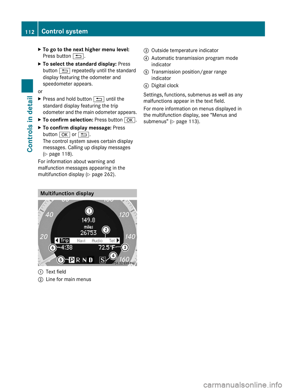
Multifunction display
:Text field;Line for main menus=Outside temperature indicator?Automatic transmission program mode
indicator
ATransmission position/gear range
indicator
BDigital clock
Settings, functions, submenus as well as any
malfunctions appear in the text field.
For more information on menus displayed in
the multifunction display, see “Menus and
submenus” (Y page 113).
112Control systemControls in detail
X204_AKB; 3; 23, en-USd2ureepe,Version: 2.11.8.12009-07-16T19:16:58+02:00 - Seite 112
Page 182 of 344
more quickly. Window fogging may impair
visibility and endanger you and others.
XSet the desired temperature
(Y page 180).
XActivating: Press button Ã.
The indicator lamp in the button comes on.
The air volume and air distribution are
adjusted automatically.
XDeactivating: Press button I, K or
_.
The indicator lamp in button à goes out.
The automatic operation of air volume and
air distribution switches off. The symbols of
air distribution or air volume appear in
display G (Y page 177).
XAdjust air distribution (Y page 181).XAdjust air volume (Y page 182).
Setting temperature
You can adjust the air temperature on each
side of the passenger compartment. You
should raise or lower the temperature setting
in small increments, preferably starting at
72‡ (22†).
You can adjust the air temperature on each
side of the passenger compartment. You
should raise or lower the temperature setting
in small increments, preferably starting at
72‡ (22†).
XIncreasing/decreasing: Turn
temperature controls : and B
(Y page 177) slightly clockwise or
counterclockwise.
Adjusting air vents
GWarning!
When operating the climate control, the air
that enters the passenger compartment
through the air vents can be very hot or very
cold (depending on the set temperature). This
may cause burns or frostbite to unprotected
skin in the immediate area of the air vents.
Always keep sufficient distance between
unprotected parts of the body and the air
vents. If necessary, use the air distribution
adjustment to direct the air to air vents in the
vehicle interior that are not in the immediate
area of unprotected skin.
For best possible performance of the climate
control:
XKeep the air intake grille in front of the
windshield free of snow, leaves, sticks, and
any other debris.
XAlways keep all air vents and grilles in the
passenger compartment free from
obstruction.
iFor draft-free ventilation, move the
adjustable center and side air vents to the
middle position.
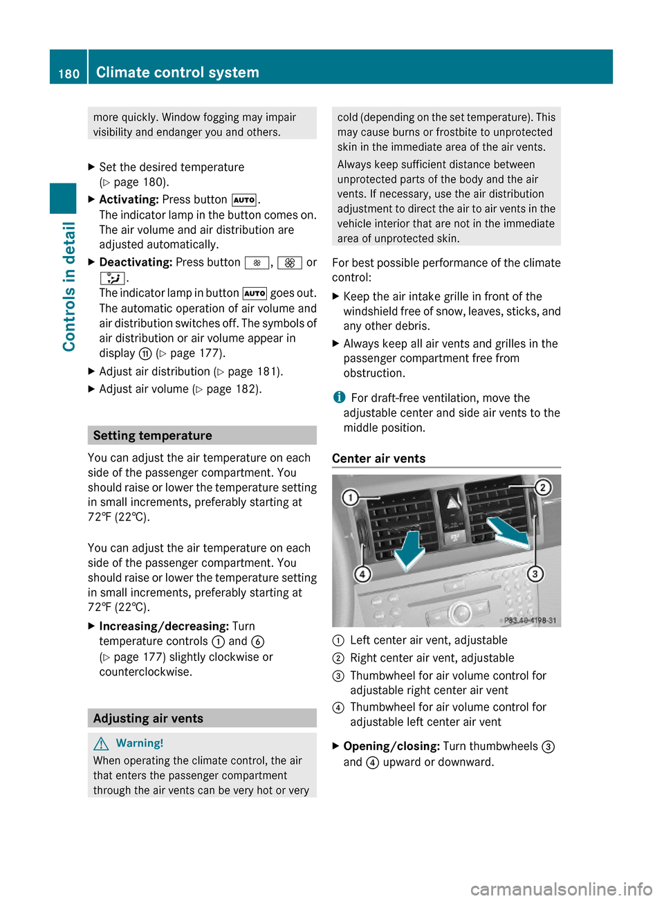
Center air vents
:Left center air vent, adjustable;Right center air vent, adjustable=Thumbwheel for air volume control for
adjustable right center air vent
?Thumbwheel for air volume control for
adjustable left center air vent
XOpening/closing: Turn thumbwheels =
and ? upward or downward.
180Climate control systemControls in detail
X204_AKB; 3; 23, en-USd2ureepe,Version: 2.11.8.12009-07-16T19:16:58+02:00 - Seite 180
Page 183 of 344
Side air vents
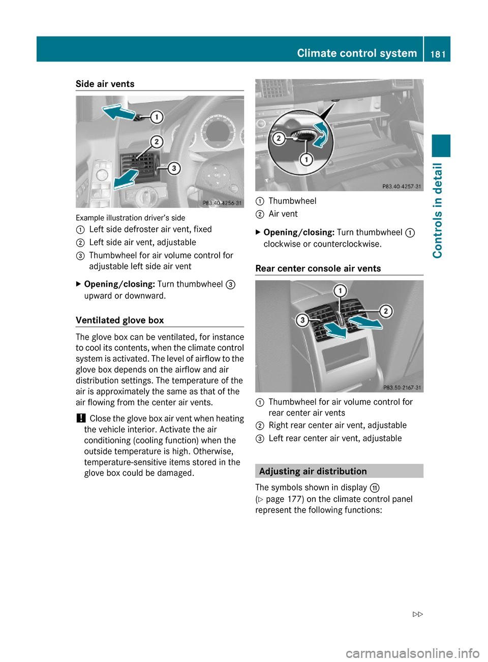
Example illustration driver’s side
:Left side defroster air vent, fixed;Left side air vent, adjustable=Thumbwheel for air volume control for
adjustable left side air vent
XOpening/closing: Turn thumbwheel =
upward or downward.
Ventilated glove box
The glove box can be ventilated, for instance
to cool its contents, when the climate control
system is activated. The level of airflow to the
glove box depends on the airflow and air
distribution settings. The temperature of the
air is approximately the same as that of the
air flowing from the center air vents.
! Close the glove box air vent when heating
the vehicle interior. Activate the air
conditioning (cooling function) when the
outside temperature is high. Otherwise,
temperature-sensitive items stored in the
glove box could be damaged.
:Thumbwheel;Air ventXOpening/closing: Turn thumbwheel :
clockwise or counterclockwise.
Rear center console air vents
:Thumbwheel for air volume control for
rear center air vents
;Right rear center air vent, adjustable=Left rear center air vent, adjustable
Adjusting air distribution
The symbols shown in display G
(Y page 177) on the climate control panel
represent the following functions:
Climate control system181Controls in detailX204_AKB; 3; 23, en-USd2ureepe,Version: 2.11.8.12009-07-16T19:16:58+02:00 - Seite 181Z
Page 312 of 344
XInsert the new bulb into the bulb carrier and
turn the bulb clockwise.
XInsert the bulb carrier and press it in.
The bulb carrier retainers ; engage
audibly.
XReconnect the plug.XClose the side trim panel (Y page 309).
License plate lamps
XPress tab ; of license plate lamp : in
direction of the arrow and loosen the lens
of license plate lamp :.
XRemove the lens of license plate lamp :.XReplace the bulb.XInsert the lens of license plate lamp : and
press it in until engages audibly.
Replacing wiper blades
Safety notes
GWarning!
For safety reasons, switch off the wipers and
remove the SmartKey from the starter switch
(vehicles with KEYLESS-GO: Make sure the
vehicle’s on-board electronics have status 0)
before replacing a wiper blade. Otherwise, the
wiper motor could suddenly turn on and cause
injury.
GWarning!
Wiper blades are components that are subject
to wear and tear. Replace the wiper blades
twice a year, preferably in the spring and fall.
Otherwise the windows will not be wiped
properly. As a result, you may not be able to
observe surrounding traffic conditions and
could cause an accident.
! To avoid damage to the hood, the front
wiper arms should only be folded forward
when in the vertical position.
! Never open the hood when a front wiper
arm is folded forward.
Hold on to the wiper when folding a wiper
arm back. If released, the force of the
impact from the tensioning spring could
crack the windshield or the rear window.
Do not allow a wiper arm to contact the
windshield glass or the rear window
without a wiper blade inserted.
Mercedes-Benz recommends that you have
this work carried out at an authorized
Mercedes-Benz Center.
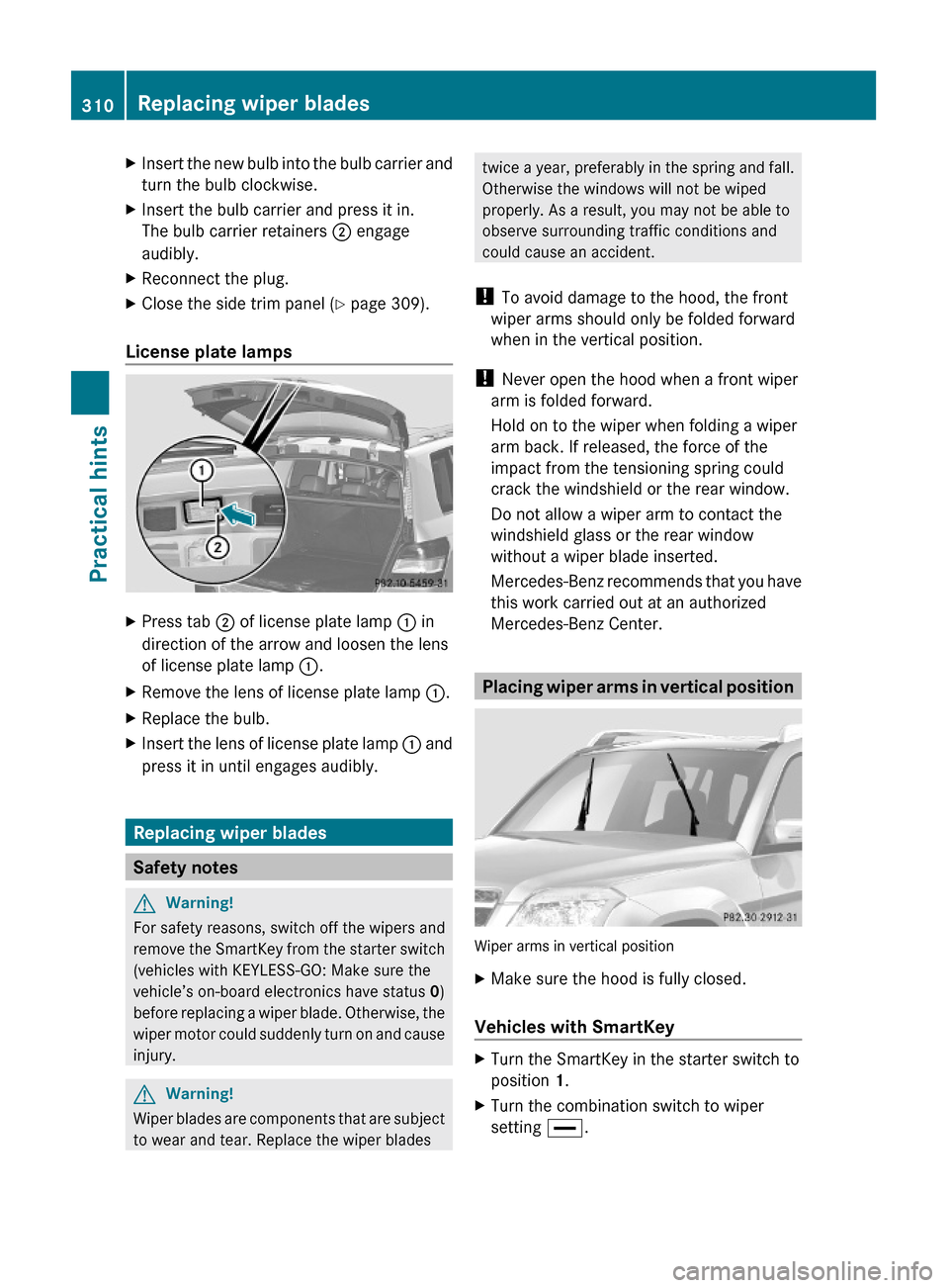
Placing wiper arms in vertical position
Wiper arms in vertical position
XMake sure the hood is fully closed.
Vehicles with SmartKey
XTurn the SmartKey in the starter switch to
position 1.
XTurn the combination switch to wiper
setting °.
310Replacing wiper bladesPractical hints
X204_AKB; 3; 23, en-USd2ureepe,Version: 2.11.8.12009-07-16T19:16:58+02:00 - Seite 310
Page 321 of 344
your vehicle model to maintain the battery
charge. Contact an authorized Mercedes-
Benz Center for further information.
The battery, the battery ventilation hose
and the lateral plug must always be
securely installed when the vehicle is in
operation.
! Never loosen or detach battery terminal
clamps while the engine is running or the
SmartKey is in the starter switch.
Otherwise the alternator and other
electronic components could be severely
damaged.
Have the battery checked regularly at an
authorized Mercedes-Benz Center.
Refer to Maintenance Booklet for
maintenance intervals or contact an
authorized Mercedes-Benz Center for
further information.
i After battery power was interrupted, do
the following:
R Reset the automatic exterior mirror fold
in function ( Y page 86).
R Set the clock (Y page 121). Vehicles with
COMAND: see separate COMAND
operating instructions.
R Synchronize the tilt/sliding panel
( Y page 186).
Charging the battery
GWarning!
Never charge a battery while still installed in
the vehicle unless the accessory battery
charge unit approved by Mercedes-Benz is
being used. Gases may escape during
charging and could cause an explosion that
may result in personal injury, paint damage or
corrosion.
An accessory battery charge unit specially
adapted for Mercedes-Benz vehicles and
tested and approved by Mercedes-Benz is
available. It permits the charging of the
battery in its installed position. Contact an
authorized Mercedes-Benz Center for
information and availability.
Charge battery in accordance with the
separate instructions for the accessory
battery charger.
Have the battery charged at an authorized
Mercedes-Benz Center. If you charge the
battery yourself, follow the operating
instructions for your charging device.
Only use a battery charge unit with a
maximum charging voltage of 14.8 V.XCharge battery in accordance with the
instructions of the battery charger
manufacturer.
Jump starting
GWarning!
Failure to follow these directions will cause
damage to the electronic components, and
can lead to a battery explosion and severe
injury or death.
Never lean over batteries while connecting or
jump starting. You might get injured.
Battery fluid contains sulfuric acid. Do not
allow this fluid to come in contact with eyes,
skin or clothing. In case it does, immediately
flush affected area with water, and seek
medical help if necessary.
A battery will also produce hydrogen gas,
which is flammable and explosive. Keep
flames or sparks away from battery, avoid
improper connection of jumper cables,
smoking, etc.
Attempting to jump start a frozen battery can
result in it exploding, causing personal injury.
Read all instructions before proceeding.
! Do not tow-start the vehicle. You could
otherwise seriously damage the automatic
Jump starting319Practical hintsX204_AKB; 3; 23, en-USd2ureepe,Version: 2.11.8.12009-07-16T19:16:58+02:00 - Seite 319Z