ESP MERCEDES-BENZ GLS SUV 2019 Owners Manual
[x] Cancel search | Manufacturer: MERCEDES-BENZ, Model Year: 2019, Model line: GLS SUV, Model: MERCEDES-BENZ GLS SUV 2019Pages: 398, PDF Size: 12.35 MB
Page 219 of 398

appears in the multifunction display. The last
active drive program is selected again.
Do not use the Offroadprogram on roads that
are snow-covered or icy or if you have installed
your vehicle with snow chains.
Selecting the Offroad program Selecting the Offroad program
X To select drive program: turn DYNAMIC
SELECT controller 0043until indicator lamp 0044
lights up.
The Drive Program "Offroad1" Max.
Drive Program "Offroad1" Max.
Speed 60 mph
Speed 60 mph message appears in the mul-
tifunction display.
The vehicle is raised by +2.4 in (60 mm).
The vehicle is lowered to normal level again if
you: R drive at speeds above 37 mph (60 km/h) (all
vehicles except Mercedes-AMG vehicles)
R drive at speeds above 43 mph (70 km/h)
(Mercedes-AMG vehicles)
R drive at speeds between 40 mph (64 km/h)
and 43 mph (70 km/h) for approximately
20 seconds (Mercedes-AMG vehicles)
The vehicle changes from the Offroaddrive pro-
gram to the Comfortdrive program if you drive
faster than 70 mph (112 km/h).
The Drive More Slowly Drive More Slowly message appears in
the multifunction display.
Further information about "Driving off-road"
(Y page 166). Off-road programs (vehicles with Off-
Road Engineering package) General notes
The Offroad andOffroad Plus drive programs
assist you when driving off-road. The engine's
performance characteristics and the gearshift-
ing characteristics of the automatic transmis-
sion are adapted for this purpose. ABS, ESP ®
and 4ETS programs especially adapted to off-
road driving are activated. An accelerator pedal
curve suitable for the terrain is selected, i.e. the accelerator pedal must be depressed further to accelerate.
Do not use the OffroadorOffroad Plus drive
programs on roads that are snow-covered or icy,
or if you have installed your vehicle with snow
chains.
Offroad drive program 0043
DYNAMIC SELECT controller
0044 Offroad program indicator lamp
Select the Offroadprogram for easily negotia-
ble off-road terrain, e.g. dirt tracks, gravel or
sandy surfaces. The engine's torque is restric-
ted to a limited degree and the drive wheels can
spin. The spinning wheels produce a cutting
effect for better traction. ABS, ESP ®
and 4ETS
programs especially adapted to off-road driving are activated. A gentle accelerator pedal curve
is also selected, i.e. the accelerator pedal must
be depressed much further in order to acceler-
ate.
You can select the Offroaddrive program at
speeds below 60 mph (96 km/h). The Drive
Drive
Program "Offroad" Max. Speed 60 mph Program "Offroad" Max. Speed 60 mph
message appears in the multifunction display. If
you drive at speeds above 60 mph (96 km/h)
and select the Offroaddrive program, the
Drive More Slowly Drive More Slowly message appears in the Driving systems
217Driving and parking Z
Page 223 of 398
006D
Level control
006E Compass with angle scale
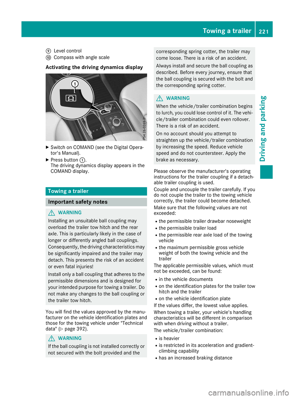
Activating the driving dynamics display X
Switch on COMAND (see the Digital Opera-
tor's Manual).
X Press button 0043.
The driving dynamics display appears in the
COMAND display. Towing a trailer
Important safety notes
G
WARNING
Installing an unsuitable ball coupling may
overload the trailer tow hitch and the rear
axle. This is particularly likely in the case of
longer or differently angled ball couplings.
Consequently, the driving characteristics may
be significantly impaired and the trailer may
detach. This presents the risk of an accident
or even fatal injuries!
Install only a ball coupling that adheres to the permissible dimensions and is designed for
your intended purpose for towing a trailer. Do
not make any changes to the ball coupling or the trailer tow hitch.
You will find the values approved by the manu-
facturer on the vehicle identification plates and
those for the towing vehicle under "Technical
data" (Y page 392). G
WARNING
If the ball coupling is not installed correctly or not secured with the bolt provided and the corresponding spring cotter, the trailer may
come loose. There is a risk of an accident.
Always install and secure the ball coupling as
described. Before every journey, ensure that
the ball coupling is secured with the bolt and
the corresponding spring cotter. G
WARNING
When the vehicle/trailer combination begins
to lurch, you could lose control of it. The vehi- cle/trailer combination could even rollover.
There is a risk of an accident.
On no account should you attempt to
straighten up the vehicle/trailer combination
by increasing the speed. Reduce vehicle
speed and do not countersteer. Apply the
brake as necessary.
Please observe the manufacturer's operating
instructions for the trailer coupling if a detach-
able trailer coupling is used.
Couple and uncouple the trailer carefully. If you do not couple the trailer to the towing vehicle
correctly, the trailer could become detached.
Make sure that the following values are not
exceeded:
R the permissible trailer drawbar noseweight
R the permissible trailer load
R the permissible rear axle load of the towing
vehicle
R the maximum permissible gross vehicle
weight of both the towing vehicle and the
trailer
The applicable permissible values, which must
not be exceeded, can be found:
R in the vehicle documents
R on the identification plates for the trailer tow
hitch and the trailer
R on the vehicle identification plate
If the values differ, the lowest value applies.
When towing a trailer, your vehicle's handling
characteristics will be different in comparison
with when driving without a trailer.
The vehicle/trailer combination:
R is heavier
R is restricted in its acceleration and gradient-
climbing capability
R has an increased braking distance Towing a trailer
221Driving and parking Z
Page 225 of 398
R
Maintain a greater distance from the vehicle
in front than when driving without a trailer.
R Avoid braking abruptly. If possible, brake gen-
tly at first to allow the trailer to run on. Then,
increase the braking force rapidly.
R The values given for gradient-climbing capa-
bilities from a standstill refer to sea level.
When driving in mountainous areas, note that
the power output of the engine and, conse-
quently, the vehicle's gradient-climbing capa- bility, decreases with increasing altitude. Installing the ball coupling
G
WARNING
If the ball coupling is not correctly installed
and secured, it can come loose during the
journey and endanger other road users. There is a risk of an accident and injury.
Always install and secure the ball coupling as
described. Before every journey, ensure that
the ball coupling is secured with the bolt and
the corresponding spring cotter. G
WARNING
If the ball coupling is not installed correctly or not secured with the bolt provided and the
corresponding spring cotter, the trailer may
come loose. There is a risk of an accident.
Always install and secure the ball coupling as
described. Before every journey, ensure that
the ball coupling is secured with the bolt and
the corresponding spring cotter. G
WARNING
If the ball coupling is not installed and secured
correctly the trailer may come loose. There is
a risk of an accident.
Install and secure the ball coupling as descri-
bed in the ball coupling installation instruc-
tions. Make sure that the ball coupling is
installed and secured correctly before every
journey. X
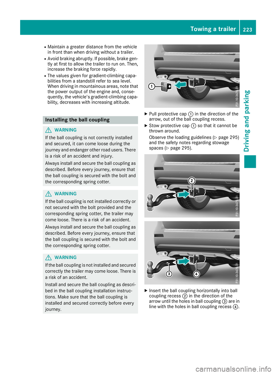
Pull protective cap 0043in the direction of the
arrow, out of the ball coupling recess.
X Stow protective cap 0043so that it cannot be
thrown around.
Observe the loading guidelines (Y page 295)
and the safety notes regarding stowage
spaces (Y page 295). X
Insert the ball coupling horizontally into ball
coupling recess 0044in the direction of the
arrow until the holes in ball coupling 0087are in
line with the holes in ball coupling recess 0085. Towing a trailer
223Driving and parking Z
Page 226 of 398
X
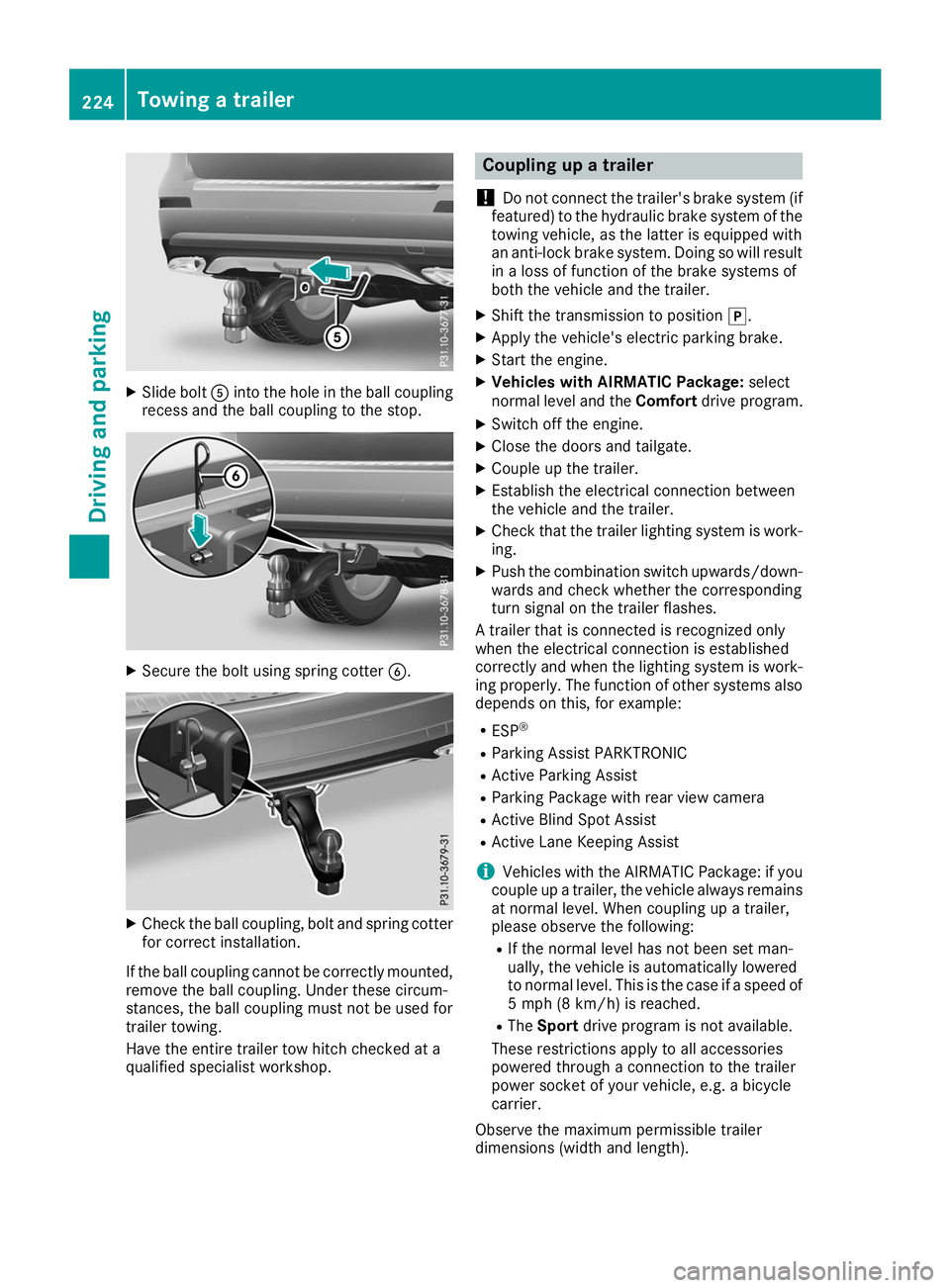
Slide bolt 0083into the hole in the ball coupling
recess and the ball coupling to the stop. X
Secure the bolt using spring cotter 0084.X
Check the ball coupling, bolt and spring cotter
for correct installation.
If the ball coupling cannot be correctly mounted,
remove the ball coupling. Under these circum-
stances, the ball coupling must not be used for
trailer towing.
Have the entire trailer tow hitch checked at a
qualified specialist workshop. Coupling up a trailer
! Do not connect the trailer's brake system (if
featured) to the hydraulic brake system of the towing vehicle, as the latter is equipped with
an anti-lock brake system. Doing so will result
in a loss of function of the brake systems of
both the vehicle and the trailer.
X Shift the transmission to position 005D.
X Apply the vehicle's electric parking brake.
X Start the engine.
X Vehicles with AIRMATIC Package: select
normal level and the Comfortdrive program.
X Switch off the engine.
X Close the doors and tailgate.
X Couple up the trailer.
X Establish the electrical connection between
the vehicle and the trailer.
X Check that the trailer lighting system is work-
ing.
X Push the combination switch upwards/down-
wards and check whether the corresponding
turn signal on the trailer flashes.
A trailer that is connected is recognized only
when the electrical connection is established
correctly and when the lighting system is work-
ing properly. The function of other systems also depends on this, for example:
R ESP ®
R Parking Assist PARKTRONIC
R Active Parking Assist
R Parking Package with rear view camera
R Active Blind Spot Assist
R Active Lane Keeping Assist
i Vehicles with the AIRMATIC Package: if you
couple up a trailer, the vehicle always remains
at normal level. When coupling up a trailer,
please observe the following:
R If the normal level has not been set man-
ually, the vehicle is automatically lowered
to normal level. This is the case if a speed of
5 mph (8 km/h) is reached.
R The Sport drive program is not available.
These restrictions apply to all accessories
powered through a connection to the trailer
power socket of your vehicle, e.g. a bicycle
carrier.
Observe the maximum permissible trailer
dimensions (width and length). 224
Towing a trailerDriving and parking
Page 228 of 398
Decoupling a trailer
G
WARNING
If you uncouple a trailer with the overrun
brake engaged, you could trap your hand
between the vehicle and the trailer drawbar.
There is a risk of injury.
Do not uncouple a trailer if the overrun brake is engaged. G
WARNING
Vehicles with level control:
The vehicle is lowered as soon as you discon-
nect the trailer cable. This could result in your limbs or those of other people that are
between the vehicle body and tires or under-
neath the vehicle being trapped. There is a
risk of injury.
Make sure that nobody is in the immediate
vicinity of the wheel housings or under the
vehicle when you disconnect the trailer cable.
! Do not disconnect a trailer with an engaged
overrun brake. Otherwise, your vehicle could
be damaged by the rebounding of the overrun
brake.
X Shift the transmission to position 005D.
X Apply the vehicle's electric parking brake.
X Start the engine.
X Close the doors and tailgate.
X Apply the trailer's parking brake.
X Detach the trailer cable and decouple the
trailer.
X Switch off the engine. Permissible trailer loads and drawbar
loads
Weight specifications Maximum allowable gross mass
The gross vehicle weight of the trailer is calcu-
lated by adding the weight of the trailer to the
weight of the load and equipment on the trailer.
You will find installing dimensions and loads
under "Technical data" (Y page 392).Permissible noseweight
You will find installing dimensions and loads
under "Technical data" (Y page 392).
Loading a trailer R
When loading the trailer, make sure that nei-
ther the permissible gross weight of the trailer
nor the gross vehicle weight are exceeded.
The permissible gross vehicle weight is indi-
cated on the identification plate located on
the B-pillar on the driver's side of the vehicle.
You can find the maximum permissible values
on the type plates of your vehicle and the
trailer. When calculating how much weight
the vehicle and trailer may carry, pay atten-
tion to the respective lowest values.
R The trailer drawbar load on the ball coupling
must be added to the rear axle load to avoid
exceeding the permissible gross axle weight.
The permissible gross vehicle weight is indi-
cated on the identification plate located on
the B-pillar on the driver's side of the vehicle.
i Mercedes-Benz recommends a trailer load
where the trailer drawbar noseweight
accounts for 8 % to 15 % of the trailer's per-
missible gross weight.
i The weight of additional accessories, pas-
sengers, and cargo reduces the permissible
trailer load and drawbar load for your vehicle.
Checking the vehicle and trailer weight R
To check that the weights of the towing vehi-
cle and the trailer comply with the maximum
permissible values, have the vehicle/trailer
combination (including the driver, passen-
gers, and cargo with a fully laden trailer)
weighed on a calibrated weighbridge.
R Check the gross axle weight rating of the front
and rear axles, the gross weight of the trailer
and the trailer drawbar noseweight. Removing the ball coupling
X Remove the spring cotter.
X Remove the bolt from the ball coupling
recess.
X Remove the ball coupling from the ball cou-
pling recess. 226
Towing a trailerDriving and pa
rking
Page 245 of 398
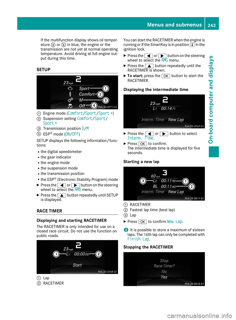
If the multifunction display shows oil temper-
ature 0085or0084 in blue, the engine or the
transmission are not yet at normal operating
temperature. Avoid driving at full engine out-
put during this time.
SETUP 0043
Engine mode (Comfort Comfort/Sport Sport/Sport +Sport +)
0044 Suspension setting Comfort
Comfort/SportSport/
Sport +
Sport +
0087 Transmission position D
D/M M
0085 ESP ®
mode (ON ON/OFFOFF)
SETUP displays the following information/func- tions:
R the digital speedometer
R the gear indicator
R the engine mode
R the suspension mode
R the transmission position
R the ESP ®
(Electronic Stability Program) mode
X Press the 0059or0065 button on the steering
wheel to select the AMG
AMGmenu.
X Press the 0063button repeatedly until SETUP
is displayed.
RACE TIMER Displaying and starting RACETIMER
The RACETIMER is only intended for use on a
closed race circuit. Do not use the function on
public roads. 0043
Lap
0044 RACETIMER You can start the RACETIMER when the engine is
running or if the SmartKey is in position 0048in the
ignition lock.
X Press the 0059or0065 button on the steering
wheel to select the AMG
AMG menu.
X Press the 0063button repeatedly until the
RACETIMER is shown.
X To start: press the 0076button to start the
RACETIMER.
Displaying the intermediate time X
Press the 0059or0065 button to select
Interm. Time Interm. Time.
X Press 0076to confirm.
The intermediate time is displayed for five
seconds.
Starting a new lap 0043
RACETIMER
0044 Fastest lap time (best lap)
0087 Lap
X Press 0076to confirm New Lap
New Lap.
i It is possible to store a maximum of sixteen
laps. The 16th lap can only be completed with
Finish Lap
Finish Lap.
Stopping the RACETIMER Menus and submenus
243On-board computer and displays Z
Page 247 of 398
Display messages
Introduction
General notes Display messages appear in the multifunction display.
Display messages with graphic displays may be shown in simplified form in the Operator's Manual
and may therefore differ from the multifunction display.
Please respond in accordance with the display messages and follow the additional notes in this
Operator's Manual.
Certain display messages are accompanied by an audible warning tone or a continuous tone.
When you stop and park the vehicle, please observe the notes on:
R HOLD function (Y page 183)
R Parking (Y page 158)
Hiding display messages X
Press the 0076or0038 button on the steering wheel.
The multifunction display hides the display message.
High-priority display messages are shown in red in the multifunction display. Some high-priority
display messages cannot be hidden.
The multifunction display shows these messages continuously until the causes for the messages
have been remedied.
Message memory The on-board computer saves certain display messages in the
message memory. You can call up
the display messages:
X Press 0059or0065 on the steering wheel to select the Serv.
Serv. menu.
If there are display messages, the multifunction display shows 2 Messages
2 Messages, for example.
X Press the 0063or0064 button to select the entry, e.g. 2 messages
2 messages.
X Press 0076to confirm.
X Press the 0063or0064 button to scroll through the display messages.
When the ignition is switched off, all display messages are deleted, apart from some high-priority
display messages. Once the causes of the high-priority display messages have been rectified, the
corresponding display messages are also deleted. Display
messages
245On-board computer and displays Z
Page 248 of 398
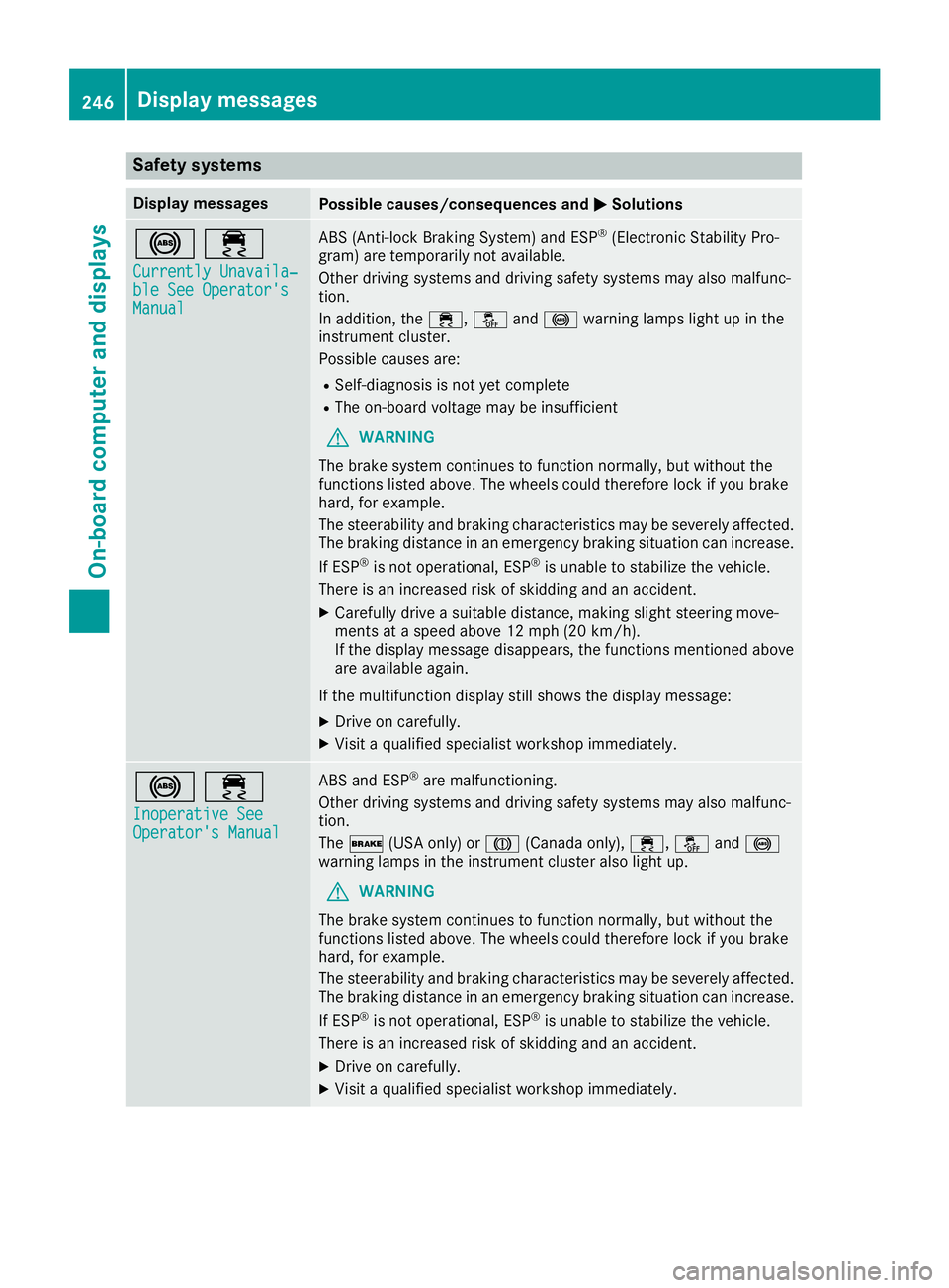
Safety systems
Display messages
Possible causes/consequences and
0050
0050Solutions 002500E5
Currently Unavaila‐
Currently Unavaila‐
ble See Operator's ble See Operator's
Manual Manual ABS (Anti-lock Braking System) and ESP
®
(Electronic Stability Pro-
gram) are temporarily not available.
Other driving systems and driving safety systems may also malfunc-
tion.
In addition, the 00E5,00BBand0025 warning lamps light up in the
instrument cluster.
Possible causes are:
R Self-diagnosis is not yet complete
R The on-board voltage may be insufficient
G WARNING
The brake system continues to function normally, but without the
functions listed above. The wheels could therefore lock if you brake
hard, for example.
The steerability and braking characteristics may be severely affected. The braking distance in an emergency braking situation can increase.
If ESP ®
is not operational, ESP ®
is unable to stabilize the vehicle.
There is an increased risk of skidding and an accident.
X Carefully drive a suitable distance, making slight steering move-
ments at a speed above 12 mph (20 km/h).
If the display message disappears, the functions mentioned above
are available again.
If the multifunction display still shows the display message:
X Drive on carefully.
X Visit a qualified specialist workshop immediately. 002500E5
Inoperative See Inoperative See
Operator's Manual Operator's Manual ABS and ESP
®
are malfunctioning.
Other driving systems and driving safety systems may also malfunc-
tion.
The 0027 (USA only) or 004D(Canada only), 00E5,00BBand0025
warning lamps in the instrument cluster also light up.
G WARNING
The brake system continues to function normally, but without the
functions listed above. The wheels could therefore lock if you brake
hard, for example.
The steerability and braking characteristics may be severely affected. The braking distance in an emergency braking situation can increase.
If ESP ®
is not operational, ESP ®
is unable to stabilize the vehicle.
There is an increased risk of skidding and an accident.
X Drive on carefully.
X Visit a qualified specialist workshop immediately. 246
Display messagesOn-board computer and displays
Page 249 of 398
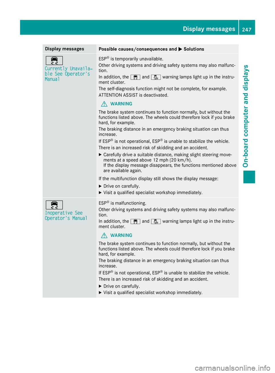
Display messages
Possible causes/consequences and
0050
0050Solutions 00E5
Currently Unavaila‐ Currently Unavaila‐
ble See Operator's ble See Operator's
Manual Manual ESP
®
is temporarily unavailable.
Other driving systems and driving safety systems may also malfunc-
tion.
In addition, the 00E5and00BB warning lamps light up in the instru-
ment cluster.
The self-diagnosis function might not be complete, for example.
ATTENTION ASSIST is deactivated.
G WARNING
The brake system continues to function normally, but without the
functions listed above. The wheels could therefore lock if you brake
hard, for example.
The braking distance in an emergency braking situation can thus
increase.
If ESP ®
is not operational, ESP ®
is unable to stabilize the vehicle.
There is an increased risk of skidding and an accident.
X Carefully drive a suitable distance, making slight steering move-
ments at a speed above 12 mph (20 km/h).
If the display message disappears, the functions mentioned above are available again.
If the multifunction display still shows the display message:
X Drive on carefully.
X Visit a qualified specialist workshop immediately. 00E5
Inoperative See Inoperative See
Operator's Manual Operator's Manual ESP
®
is malfunctioning.
Other driving systems and driving safety systems may also malfunc-
tion.
In addition, the 00E5and00BB warning lamps light up in the instru-
ment cluster.
G WARNING
The brake system continues to function normally, but without the
functions listed above. The wheels could therefore lock if you brake
hard, for example.
The braking distance in an emergency braking situation can thus
increase.
If ESP ®
is not operational, ESP ®
is unable to stabilize the vehicle.
There is an increased risk of skidding and an accident.
X Drive on carefully.
X Visit a qualified specialist workshop immediately. Display messages
247On-board computer and displays Z
Page 250 of 398
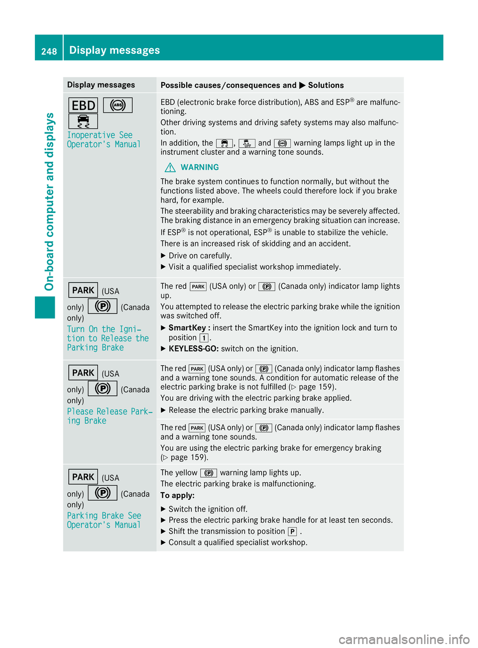
Display messages
Possible causes/consequences and
0050
0050Solutions 007A
0025
00E5 Inoperative See
Inoperative See
Operator's Manual Operator's Manual EBD (electronic brake force distribution), ABS and ESP
®
are malfunc-
tioning.
Other driving systems and driving safety systems may also malfunc-
tion.
In addition, the 00E5,00BBand0025 warning lamps light up in the
instrument cluster and a warning tone sounds.
G WARNING
The brake system continues to function normally, but without the
functions listed above. The wheels could therefore lock if you brake
hard, for example.
The steerability and braking characteristics may be severely affected. The braking distance in an emergency braking situation can increase.
If ESP ®
is not operational, ESP ®
is unable to stabilize the vehicle.
There is an increased risk of skidding and an accident.
X Drive on carefully.
X Visit a qualified specialist workshop immediately. 0049
(USA
only) 0024 (Canada
only)
Turn On the Igni‐
Turn On the Igni‐
tion tion to
toRelease
Release the
the
Parking Brake
Parking Brake The red
0049(USA only) or 0024(Canada only) indicator lamp lights
up.
You attempted to release the electric parking brake while the ignition
was switched off.
X SmartKey : insert the SmartKey into the ignition lock and turn to
position 0047.
X KEYLESS-GO: switch on the ignition. 0049
(USA
only) 0024 (Canada
only)
Please
Please Release Release Park‐
Park‐
ing Brake
ing Brake The red
0049(USA only) or 0024(Canada only) indicator lamp flashes
and a warning tone sounds. A condition for automatic release of the
electric parking brake is not fulfilled (Y page 159).
You are driving with the electric parking brake applied.
X Release the electric parking brake manually. The red
0049(USA only) or 0024(Canada only) indicator lamp flashes
and a warning tone sounds.
You are using the electric parking brake for emergency braking
(Y page 159). 0049
(USA
only) 0024 (Canada
only)
Parking Brake See
Parking Brake See
Operator's Manual Operator's Manual The yellow
0024warning lamp lights up.
The electric parking brake is malfunctioning.
To apply:
X Switch the ignition off.
X Press the electric parking brake handle for at least ten seconds.
X Shift the transmission to position 005D.
X Consult a qualified specialist workshop. 248
Display
messagesOn-board computer and displays