transmission MERCEDES-BENZ GLS SUV 2020 Workshop Manual
[x] Cancel search | Manufacturer: MERCEDES-BENZ, Model Year: 2020, Model line: GLS SUV, Model: MERCEDES-BENZ GLS SUV 2020Pages: 549, PDF Size: 9.9 MB
Page 393 of 549
to
wing eye. Fasten theto w bar tothe trailer
hitch.
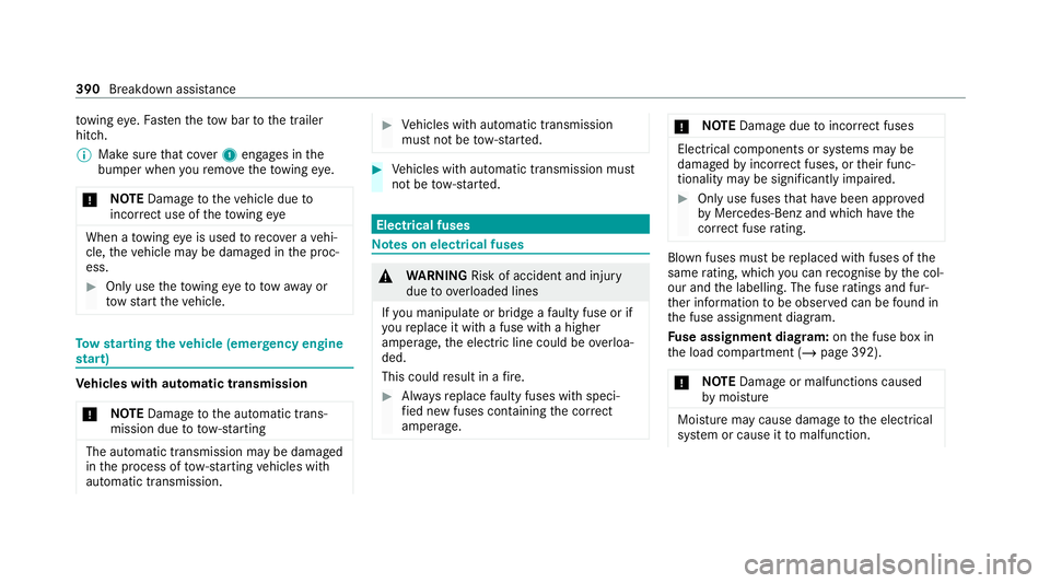
% Make sure that co ver1 engages in the
bumper when youre mo vetheto wing eye.
* NO
TEDama getotheve hicle due to
incor rect use of theto wing eye When a
towing eye is used toreco ver a vehi‐
cle, theve hicle may be damaged in the proc‐
ess. #
Only use theto wing eyeto to waw ay or
to w start theve hicle. To
w starting theve hicle (eme rgency engine
st art) Ve
hicles with automatic transmission
* NO
TEDama getothe automatic trans‐
mission due to tow-starting The automatic transmission may be damaged
in the process of tow- starting vehicles with
automatic transmission. #
Vehicles with automatic transmission
must not be tow- star ted. #
Vehicles with automatic transmission must
not be tow- star ted. Electrical fuses
Note
s on electrical fuses &
WARNING Risk of accident and inju ry
due to ov erloaded lines
If yo u manipulate or bridge a faulty fuse or if
yo ure place it with a fuse with a higher
amperage, the electric line could be overloa‐
ded.
This could result in a fire. #
Alw aysre place faulty fuses with speci‐
fi ed new fuses conta iningthe cor rect
amperage. *
NO
TEDama gedue toincor rect fuses Electrical components or sy
stems may be
damaged byincor rect fuses, or their func‐
tionality may be significant lyimpaired. #
Only use fuses that ha vebeen appr oved
by Mercedes-Benz and which ha vethe
cor rect fuse rating. Blown fuses mu
stbe replaced with fuses of the
same rating, which you can recognise bythe col‐
our and the labelling. The fuse ratings and fur‐
th er information tobe obser ved can be found in
th e fuse assignment diagram.
Fu se assignment diag ram: onthe fuse box in
th e load compartment (/ page 392).
* NO
TEDama geor malfunctions caused
by moisture Moisture may cause dama
getothe electrical
sy stem or cause it tomalfunction. 390
Breakdown assi stance
Page 405 of 549
Preparing
theve hicle for a wheel change Re
quirements:
R The requ ired tyre-change tool kit is available.
If yo ur vehicle is not equipped with the tyre-
ch ange tool kit, consult a qualified specialist
wo rkshop tofind out about suitable tools.
R The vehicle is not on a slope.
R The vehicle is on solid, non-slippery and le vel
ground. #
Apply the electric parking brake manually. #
Movethe front wheels tothest ra ight-ahead
position. #
Shift the transmission toposition j. #
Vehicles with le vel control sy stem: setthe
normal vehicle le vel (/ page 265). #
Swit choff the engine. #
Make sure that the engine cann otbe star ted. #
Place choc ks orother suitable items under
th e front and rear of the wheel that is diago‐
nally opposite the wheel you wish tochange. #
Raise theve hicle (/ page 403). Ad
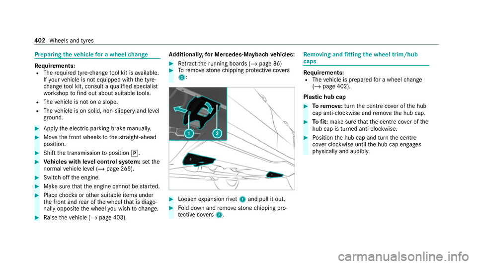
ditionall y,for Me rcedes-Mayba chvehicles: #
Retract theru nning boards (/ page 86) #
Toremo vestone chipping pr otective co vers
2 : #
Loosen expansion rive t1 and pull it out. #
Fold down and remo vestone chipping pro‐
te ctive co vers 2 . Re
moving and fitting the wheel trim/hub
caps Re
quirements:
R The vehicle is prepared for a wheel change
(/ page 402).
Pla stic hub cap #
Toremo ve:turn the cent recover of the hub
cap anti-clockwise and remo vethe hub cap. #
Tofit: make sure that the cent recover of the
hub cap is turned anti-clockwise. #
Position the hub cap and turn the cent re
co ver clockwise until the hub cap engages
ph ysically and audibly. 402
Wheels and tyres
Page 417 of 549
#
When operating two-w ayradios in the
ve hicle, alw ays connect them tothe
lo w- reflection exterior aerial. *
NO
TEInva lidation of the operating per‐
mit due tofailure tocomply wi th the
instructions for ins tallation and use The operating permit may be in
validated if
th e instructions for ins tallation and use of
two-w ayradios are not obser ved. #
Only use appr oved frequency bands. #
Obser vethe maximum permissible out‐
put po wer in these frequency bands. #
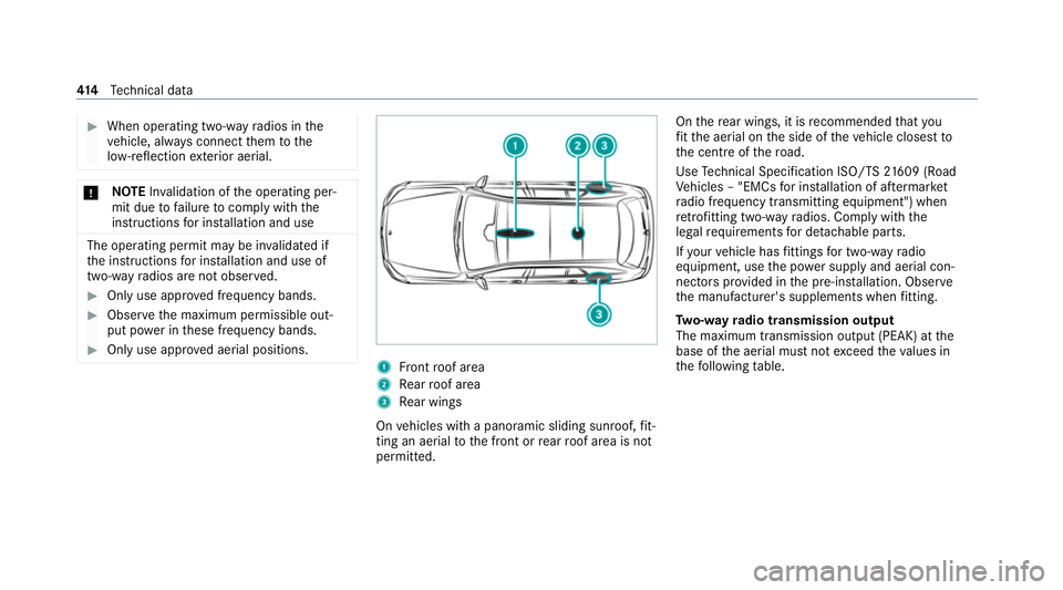
Only use appr oved aerial positions. 1
Front roof area
2 Rear roof area
3 Rear wings
On vehicles with a panoramic sliding sunroof, fit‐
ting an ae rial to the front or rear roof area is not
permitted. On
there ar wings, it is recommended that you
fi t th e aerial on the side of theve hicle closest to
th e cent reofthero ad.
Use Tech nical Specification ISO/TS 21609 (Road
Ve hicles – "EMCs for ins tallation of af term arket
ra dio frequency transmitting equipment") when
re trofitting two-w ayradios. Comply with the
legal requirements for de tach able parts.
If yo ur vehicle has fittings for two-w ayradio
equipment, use the po wer supp lyand aerial con‐
nec tors prov ided in the pre-ins tallation. Obser ve
th e manufacturer's supplements when fitting.
Tw o-w ayradio transmission output
The maximum transmission output (PEAK) at the
base of the aerial must not exceed theva lues in
th efo llowing table. 414
Tech nical da ta
Page 418 of 549
Fr
equency band and maximum transmission
output Fr
equency band Maximum transmis‐
sion output
Sho rtwa ve
3 - 54 MHz 10
0 W
4 m frequency band
74 - 88 MHz 30 W
2 m frequency band
14 4 - 174 MHz 50 W
Te rrestrial Trunked
Ra dio (TETRA)
380 - 460 MHz 10 W
70 cm frequency
band
420 - 450 MHz 35 W
Tw o-w ayradio
(2G/3G/4G) 10 W The
following can be used in theve hicle without
re strictions:
R two-w ayradios with a maximum transmission
output of up to100 mW
R RF transmitters with transmitter frequencies
in the 380 - 410 MHz frequency band and a
maximum transmission output of up to2 W
(TETRA)
R mobile phones (2G/3G/4G)
There are no restrictions when positioning the
aerial on the outside of theve hicle forth efo llow‐
ing frequency bands:
R Terrestrial Trunked Radio (TETRA)
R 70 cm frequency band
R 2G/3G/4G Ra
dio ope rating permits forve hicle comp o‐
nents
Manufacturer information about wireless vehicle
components can be found using theke y phrase
"Radio operating permits" in the Digital Owner's Manual in
theve hicle, on the internet and in the
app. Ve
hicle identification plate, VIN and engine
number overview
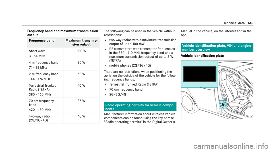
Ve hicle identification plate Te
ch nical da ta415
Page 446 of 549
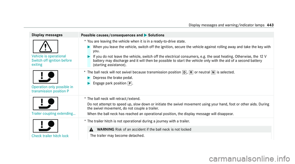
Display messages
Possible causes/consequences and M
MSolutions
d Vehicle is operational
Switch off ignition before
exiting *Y
ou are leaving theve hicle when it is in a ready-to-drive state. #
When you lea vetheve hicle, switch off the ignition, secure theve hicle against rolling away and take theke y with
yo u. #
Ifyo u do not lea vetheve hicle, switch off the electrical consumers, e.g. the seat heating. Otherwise, the12 V
battery may dischar geand it will then be possible tostart theve hicle only with the aid of a second battery
(s ta rting assis tance).
ï Operation only possible in
transmission position P *
The ball neck will not swivel because transmission position h,kor neutral iis selected. #
Dep ress the brake pedal. #
Enga gepark position j.
ï
Trailer coupling extending… *T
he ball neck will retract/ extend.
Do not attem pttospeed up, slow down or initiate the swivel mo vement using your hand, foot or other aids. During
th e swivel mo vement, do not couple a trailer.
When the ball neck has reached an operational position, the display message will disappear.
ï
Check trailer hitch lock *T
he trailer hitch is not operational during a journey with a trailer. &
WARNING Risk of an accident if the ball neck is not loc ked
The trailer may become de tach ed. Display messages and
warning/indicator lamps 443
Page 456 of 549
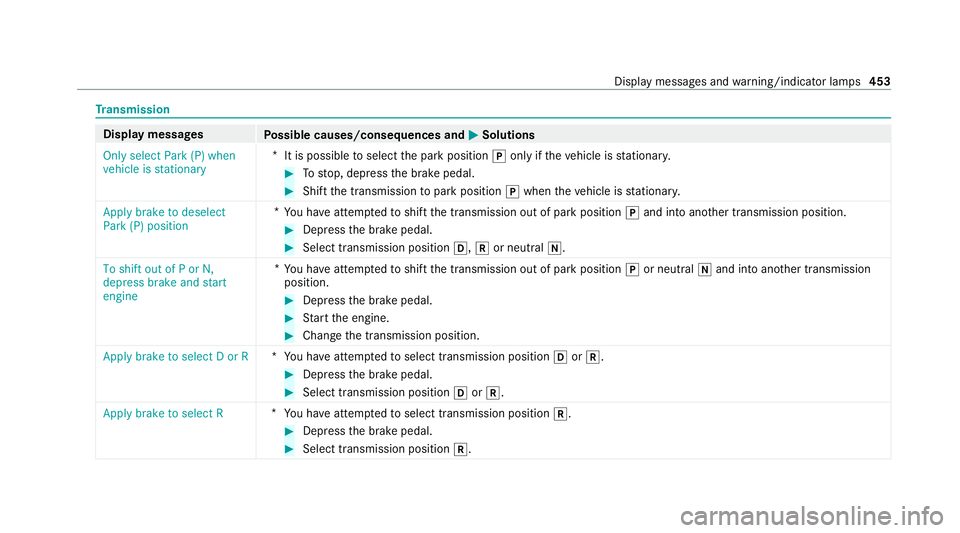
Tr
ansmission Display messages
Possible causes/consequences and M
MSolutions
Only select Park (P) when
vehicle is stationary *
It is possible toselect the park position jonly if theve hicle is stationar y. #
Tostop, depress the brake pedal. #
Shift the transmission topark position jwhen theve hicle is stationar y.
Apply brake to deselect
Park (P) position *
Yo u ha veattem ptedto shift the transmission out of park position jand into ano ther transmission position. #
Depress the brake pedal. #
Select transmission position h,kor neutral i.
To shift out of P or N,
depress brake and start
engine *
Yo u ha veattem ptedto shift the transmission out of park position jor neutral iand into ano ther transmission
position. #
Depress the brake pedal. #
Start the engine. #
Change the transmission position.
Apply brake to select D or R *
You ha veattem ptedto select transmission position hork. #
Depress the brake pedal. #
Select transmission position hork.
Apply brake to select R *
You ha veattem ptedto select transmission position k. #
Depress the brake pedal. #
Select transmission position k. Display messages and
warning/indicator lamps 453
Page 457 of 549
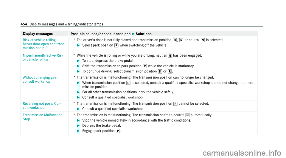
Display messages
Possible causes/consequences and M
MSolutions
Risk of vehicle rolling
Driver door open and trans-
mission not in P *
The driver's door is not fully closed and transmission position h,kor neutral iis selected. #
Select park position jwhen switching off theve hicle.
N permanently active Risk
of vehicle rolling *
While theve hicle is rolling or while you are driving, neutral ihas been en gage d. #
Tostop, depress the brake pedal. #
Shift the transmission topark position jwhile theve hicle is stationar y. #
Tocontinue driving, select transmission position hork.
Without changing gear,
consult workshop *T
he transmission is malfunctioning. The transmission position can no longer be changed. #
When transmission position his selec ted, consult a qualified specialist workshop and do not change the trans‐
mission position. #
For all other transmission positions, park theve hicle safely. #
Consult a qualified specialist workshop.
Reversing not poss. Con-
sult workshop *
The transmission is malfunctioning. The transmission position kcannot be selected. #
Consult a qualified specialist workshop.
Transmission Malfunction
Stop *
The transmission is malfunctioning. The transmission shifts toneutral iautomatically. #
Stop theve hicle immediately in accordance with the traf fic conditions. #
Depress the brake pedal. #
Enga gepark position j.454
Display messages and warning/indicator lamps
Page 458 of 549
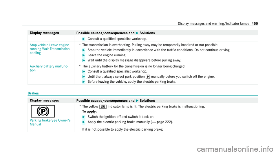
Display messages
Possible causes/consequences and M
MSolutions #
Consult a qualified specialist workshop.
Stop vehicle Leave engine
running Wait Transmission
cooling *T
he transmission is overheating. Pulling away may be temp orarily impaired or not possible. #
Stop theve hicle immediately in accordance with the traf fic conditions. Do not continue driving. #
Lea vethe engine running. #
Wait until the display message disappears before pulling away.
Auxiliary battery malfunc-
tion *T
he auxiliary batteryforth e transmission is no longer being charge d. #
Consult a qualified specialist workshop. #
Untilthen, alw ays select park position jmanually before you swit choff the engine. #
Before leaving theve hicle, apply the electric parking brake. Brakes
Display messages
Possible causes/consequences and M MSolutions
! Parking brake See Owner's
Manual *
The yellow ! indicator lamp is lit. The elect ric pa rking brake is malfunctioning.
To appl y: #
Switch the ignition off and switch it back on. #
Apply the electric parking brake manually (/ page 222).
If it is not possible toapply the electric parking brake: Display messages and
warning/indicator lamps 455
Page 499 of 549
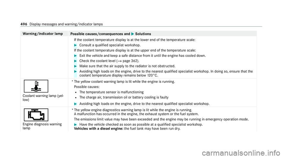
Wa
rning/indicator lamp
Possible causes/consequences and M
MSolutions
If th e coolant temp erature display is at the lo wer end of thete mp erature scale: #
Consult a qualified specialist workshop.
If th e coolant temp erature display is at the upper end of thete mp erature scale: #
Exit theve hicle and keep a safe dis tance from it until the engine has cooled down. #
Check the coolant le vel (/ page 362). #
Make sure that the air supply tothera diator is not obstructed. #
Avoiding high loads on the engine, drive tothe nearest qualified specialist workshop. In doing so, ensure that the
coolant temp erature display remains below 120°C.
ÿ Coolant warning lamp (yel‐
low) *T
he yellow coolant warning lamp is lit while the engine is running.
Po ssible causes:
R The temp erature sensor is malfunctioning
R The charge air, transmission oil or bat tery cooling is faulty #
Avoiding high loads on the engine, drive tothe nearest qualified specialist workshop.
;
Engine diagnosis warning
lamp *T
he yellow engine diagno stics warning lamp is lit while the engine is running.
A malfunction has occu rred in the engine, theex haust sy stem or the fuel sy stem.
The emissions limit value may ha vebeen exceeded and the engine may be running in emergency operation mode. #
Have theve hicle checked as soon as possible at a qualified specialist workshop.
Ve hicles with a diesel engine: the fuel tank may ha vebeen run dr y. 496
Display messages and warning/indicator lamps
Page 512 of 549
Au
tomatic car wash mode
Ac tivating.............................................. 366
Au tomatic distance control
see Active Dis tance Assi stDISTRONIC
Au tomatic driving lights ...........................157
Au tomatic engine start (ECO start/
sto p function)............................................ 197
Au tomatic engine stop (ECO start/
sto p function)............................................ 197
Au tomatic front passen ger front air‐
bag deacti vation sy stem
see Automatic front passenger front
airbag shutoff
Au tomatic front passen ger front air‐
bag shu toff
Fu nction of the automatic front
passenger front airbag deactivation
sy stem..................................................... 48
PA SSENGER AIR BAG indicator lamp....... 50
Au tomatic measures af ter an accident..... 54
Au tomatic mir rorfo lding function
Ac tivating/deactivating......................... 172Au
tomatic seat adjustment
Setting................................................... 12 0
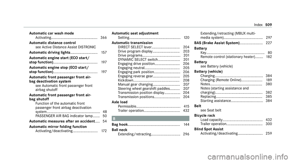
Au tomatic transmission
DIRECT SELECT le ver............................ 204
Drive program displa y........................... 203
Drive programs...................................... 201
DY NA MIC SELECT switch...................... 201
Engaging drive position......................... 206
Engaging neutral................................... 205
Engaging park position.......................... 206
Engaging reve rsege ar........................... 205
Kickdown............................................. .208
Manual gear changing.......................... .207
St eering wheel gearshift paddles.......... 207
Tr ansmission position displa y................ 204
Tr ansmission position s.......................... 204
Axle load Perm issible............................................ 41 5
Tr ailer operation.................................... 432 B
Bag hook .................................................... 14 4
Ball ne ck
Extending/r etra cting............................ .296 Extending/r
etra cting (MBUX multi‐
media sy stem)....................................... 297
BA S (Brake Assist Sy stem)....................... 227
Battery Key.......................................................... 80
Re mo tecontrol (s tationary heater)........ 182
Battery see Battery (vehicle)
Battery (vehicle) Charging................................................ 384
Charging (Remo teOnline)..................... 189
No tes....................................................3 80
No tes (s tarting assis tance and
ch arging)............................................... 382
Re placing.............................................. 385
St arting assis tance................................ 384
Belt see Seat belt
Bic ycle rack
Load capacity........................................ 432
Tr ailer operation.................................... 300
Blind Spot Assist Activating/deactivating......................... 259 Index
509