mirror MERCEDES-BENZ M-Class 2014 W166 Owner's Guide
[x] Cancel search | Manufacturer: MERCEDES-BENZ, Model Year: 2014, Model line: M-Class, Model: MERCEDES-BENZ M-Class 2014 W166Pages: 462, PDF Size: 6.23 MB
Page 117 of 462

Folding the exterior mirrors in or out
electrically X
Make sure that the SmartKey is in position
1 or 2in the ignition lock.
X Briefly press button 0002.
Both exterior mirrors fold in or out.
i Make sure that the exterior mirrors are
always folded out fully while driving .They
could otherwise vibrate.
i If you are driving faster than
30 mph (47 km/h), you can no longer fold
in the exterior mirrors.
Setting the exterior mirrors If the battery has been disconnected or
completely discharged, the exterior mirrors
must be reset. The exterior mirrors will
otherwise not fold in when you select the
"Fold in mirrors when locking" function in the
on-board computer (Y page 277).
X Make sure that the SmartKey is in
position 1in the ignition lock.
X Briefly press button 0002.
Folding the exterior mirrors in or out
automatically If the "Fold in mirrors when locking" function
is activated in the on-board computer:
(Y page 277) R
the exterior mirrors fold in automatically as
soon as you lock the vehicle from the
outside.
R the exterior mirrors fold out again
automatically as soon as you unlock the
vehicle and then open the driver's or front-
passenger door.
Exterior mirror pushed out of position If an exterior mirror has been pushed out of
position, proceed as follows:
X
Vehicles without electrically folding
exterior mirrors: move the exterior mirror
into the correct position manually.
X Vehicles with electrically folding
exterior mirrors: press and hold button for
folding the mirrors 0002(Ypage 115) until you
hear a click and then the mirror engage in
position.
The mirror housing is engaged again and
you can adjust the exterior mirrors as usual
(Y page 114). Automatic anti-glare mirrors
The rear-view mirror and the exterior mirror
on the driver's side automatically go into anti-
glare mode if the following conditions are met
simultaneously:
R the ignition is switched on and
R incident light from headlamps strikes the
sensor in the rear-view mirror.
i The mirrors do not go into anti-glare mode
if reverse gear is engaged or if the interior
lighting is switched on. Mirrors
115Seats, steering wheel and mirrors Z
Page 118 of 462
Parking position for the exterior
mirror on the front-passenger side
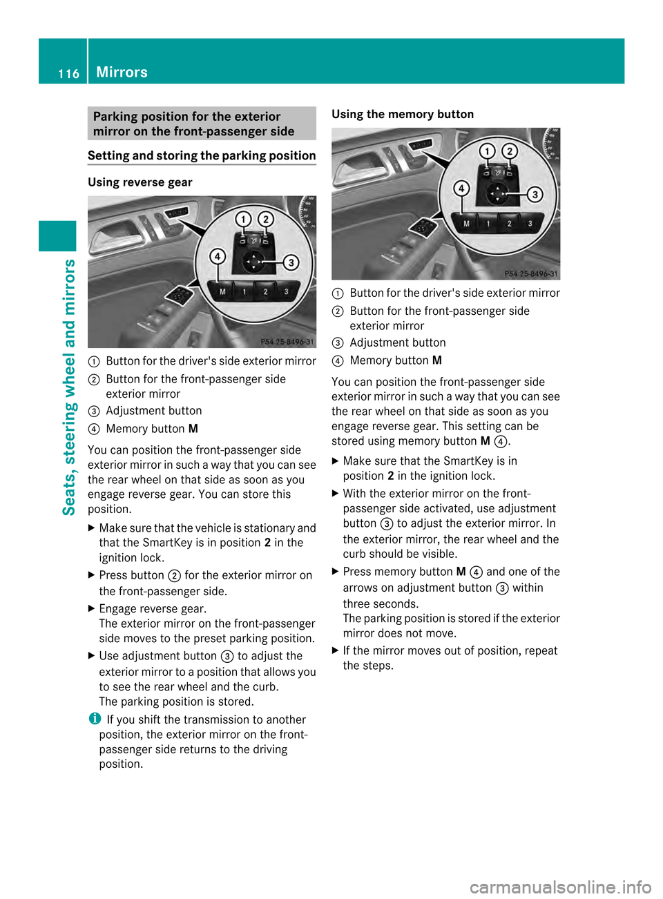
Setting and storing the parking position Using reverse gear
0002
Button for the driver's side exterior mirror
0003 Button for the front-passenger side
exterior mirror
0023 Adjustment button
0022 Memory button M
You can position the front-passenger side
exterior mirror in such a way that you can see
the rear wheel on that side as soon as you
engage reverse gear. You can store this
position.
X Make sure that the vehicle is stationary and
that the SmartKey is in position 2in the
ignition lock.
X Press button 0003for the exterior mirror on
the front-passenger side.
X Engage reverse gear.
The exterior mirror on the front-passenger
side moves to the preset parking position.
X Use adjustment button 0023to adjust the
exterior mirror to a position that allows you
to see the rear wheel and the curb.
The parking position is stored.
i If you shift the transmission to another
position, the exterior mirror on the front-
passenger side returns to the driving
position. Using the memory button
0002
Button for the driver's side exterior mirror
0003 Button for the front-passenger side
exterior mirror
0023 Adjustment button
0022 Memory button M
You can position the front-passenger side
exterior mirror in such a way that you can see
the rear wheel on that side as soon as you
engage reverse gear. This setting can be
stored using memory button M0022.
X Make sure that the SmartKey is in
position 2in the ignition lock.
X With the exterior mirror on the front-
passenger side activated, use adjustment
button 0023to adjust the exterior mirror. In
the exterior mirror, the rear wheel and the
curb should be visible.
X Press memory button M0022 and one of the
arrows on adjustment button 0023within
three seconds.
The parking position is stored if the exterior
mirror does not move.
X If the mirror moves out of position, repeat
the steps. 116
MirrorsSeats, steering wheel and mirrors
Page 119 of 462
Calling up a stored parking position
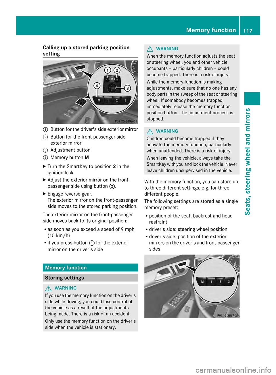
setting 0002
Butto nfor the driver's side exterior mirror
0003 Button for the front-passenger side
exterior mirror
0023 Adjustment button
0022 Memory button M
X Turn the SmartKey to position 2in the
ignition lock.
X Adjust the exterior mirror on the front-
passenger side using button 0003.
X Engage reverse gear.
The exterior mirror on the front-passenger
side moves to the stored parking position.
The exterior mirror on the front-passenger
side moves back to its original position:
R as soon as you exceed a speed of 9mph
(15 km/h)
R if you press button 0002for the exterior
mirror on the driver's side Memory function
Storing settings
G
WARNING
If you use the memor yfunctio nonthe driver's
side while driving, you could lose control of
the vehicle as a result of the adjustments
being made. There is a risk of an accident.
Only use the memory function on the driver's
side when the vehicle is stationary. G
WARNING
When the memory function adjusts the seat
or steering wheel, you and other vehicle
occupants –particularly childre n–could
become trapped. There is a risk of injury.
While the memory function is making
adjustments, make sure that no one has any
body parts in the sweep of the seat or steering
wheel. If somebody becomes trapped,
immediately release the memory function
position button .The adjustment process is
stopped. G
WARNING
Children could become trapped if they
activate the memory function, particularly
when unattended. There is arisk of injury.
When leaving the vehicle, always take the
SmartKey with you and lock the vehicle. Never
leave children unsupervised in the vehicle.
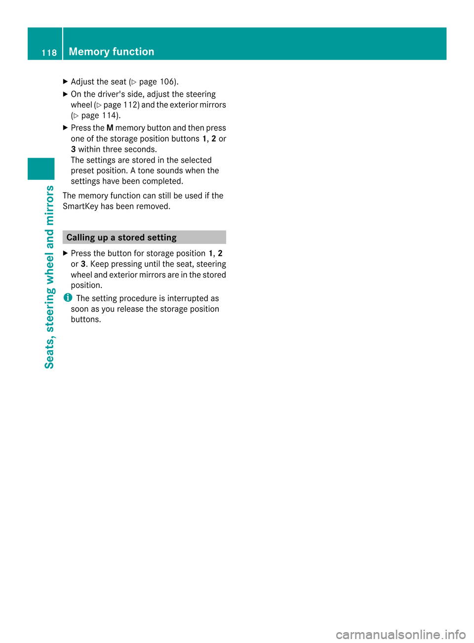
With the memory function, you can store up
to three different settings, e.g. for three
differen tpeople.
The following settings are stored as a single
memory preset:
R position of the seat, backrest and head
restraint
R driver's side: steering wheel position
R driver's side: position of the exterior
mirrors on the driver's and front-passenger
sides Memory function
117Seats, steering wheel and mirrors Z
Page 120 of 462
X
Adjust the sea t(Ypage 106).
X On the driver's side, adjust the steering
wheel (Y page 112 )and the exterio rmirrors
(Y page 114).
X Press the Mmemory button and the npress
one of the storage position buttons 1,2or
3 withi nthree seconds.
The settings are stored in the selected
preset position. Atone sounds when the
settings have been completed.
The memory function can still be used if the
SmartKey has been removed. Calling up
astore dsetting
X Press the button for storage position 1,2
or 3.K eep pressing until the seat, steering
wheel and exterior mirror sare in the stored
position.
i The setting procedure is interrupted as
soon as you release the storage position
buttons. 118
Memory functionSeats, steering wheel and mirrors
Page 222 of 462
Once you have exited the parking space
completely, the steering wheel is moved to
the straight-ahead position. You hear a tone
and the
Park Assist Switched Off message appears in the multifunction
display. You will then have to steer and merge
into traffic on your own. PARKTRONIC is still
available. You can take over the steering,
before the vehicle has exited the parking
space completely. This is useful, for example
when you recognize that it is already possible
to pull out of the parking space.
Canceling Active Parking Assist
X
Stop the movement of the multifunction
steering wheel or steer yourself.
Active Parking Assist will be canceled at
once. The Park Assist Canceled message appears in the multifunction
display.
or
X Press the PARKTRONIC button on the
center console (Y page 215).
PARKTRONIC is switched off and Active
Parking Assist is immediately canceled.
The Park Assist Canceled message
appears in the multifunction display.
Active Parking Assist is canceled
automatically if:
R the electric parking brake is engaged
R transmission position Pis selected
R parking using Active Parking Assist is no
longer possible
R you are driving faster than 6 mph
(10 km/h)
R a wheel spins, ESP ®
intervenes or fails. The
000F warning lamp lights up in the
instrument cluster.
Aw arning tone sounds. The parking symbol
disappears and the multifunction display
shows the Park Assist Canceled message.
If Active Parking Assist is canceled, you must
steer again yourself. Towing
atrailer For vehicles with a trailer tow hitch, the
minimum length for parking spaces is slightly
increased.
If you have attached a trailer to your vehicle,
you should not use Active Parking Assist.
Once the electrical connectio
nis established
between your vehicle and the trailer, Active
Parking Assist is no longer available.
PARKTRONIC is deactivated for the rear area. Rear view camera
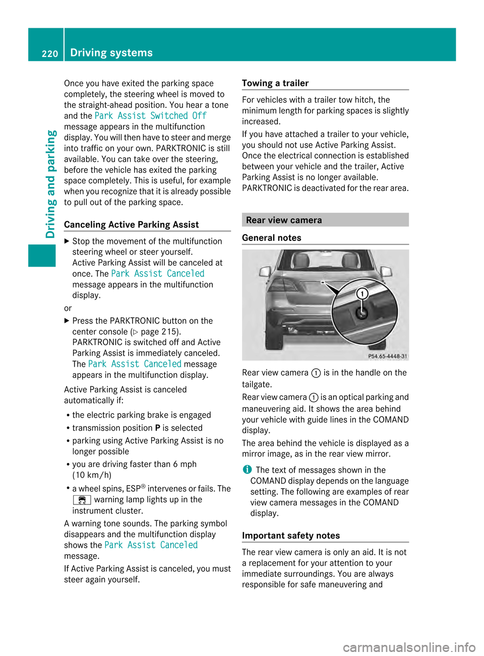
General notes Rear view camera
0002is in the handle on the
tailgate.
Rear view camera 0002is an optical parking and
maneuvering aid. It shows the area behind
your vehicle with guide lines in the COMAND
display.
The area behind the vehicle is displayed as a
mirror image, as in the rear view mirror.
i The text of messages shown in the
COMAND display depends on the language
setting. The following are examples of rear
view camera messages in the COMAND
display.
Important safety notes The rear view camera is only an aid. It is not
a replacement for your attention to your
immediate surroundings. You are always
responsible for safe maneuvering and220
Driving systemsDriving and parking
Page 224 of 462
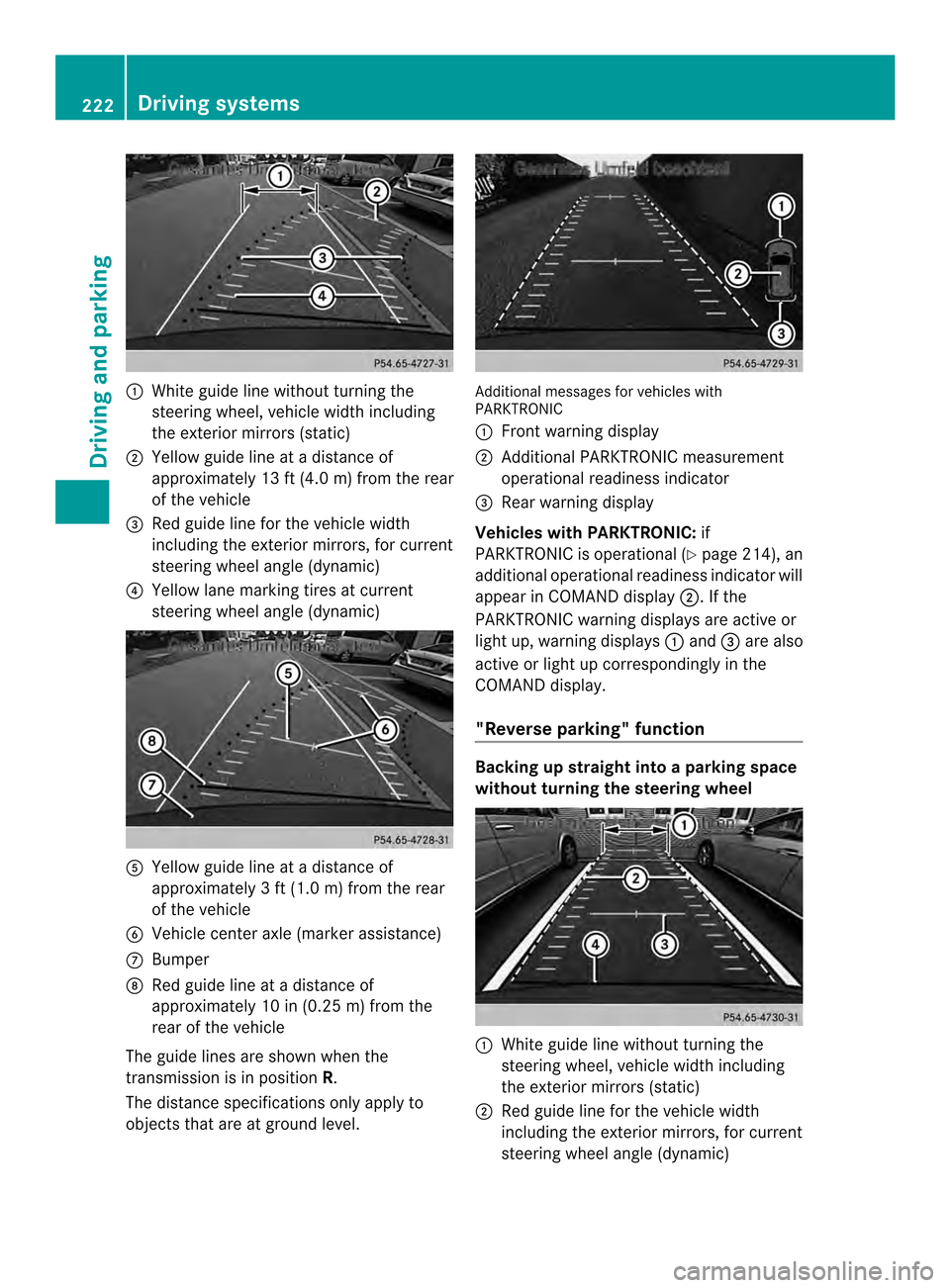
0002
White guide line without turning the
steering wheel, vehicle width including
the exterior mirrors (static)
0003 Yellow guide line at a distance of
approximately 13 ft (4.0 m) from the rear
of the vehicle
0023 Red guide line for the vehicle width
including the exterior mirrors, for current
steering wheel angle (dynamic)
0022 Yellow lane marking tires at current
steering wheel angle (dynamic) 0020
Yellow guide line at a distance of
approximately 3 ft (1.0 m) from the rear
of the vehicle
0021 Vehicle center axle (marker assistance)
0014 Bumper
0015 Red guide line at a distance of
approximately 10 in (0.25 m) from the
rear of the vehicle
The guide lines are show nwhen the
transmission is in position R.
The distance specifications only apply to
objects that are at ground level. Additional messages for vehicles with
PARKTRONIC
0002
Front warning display
0003 Additional PARKTRONIC measurement
operational readiness indicator
0023 Rear warning display
Vehicles with PARKTRONIC: if
PARKTRONIC is operational (Y page 214), an
additional operational readiness indicator will
appearinC OMAND display 0003. If the
PARKTRONIC warning displays are active or
light up, warning displays 0002and 0023are also
active or light up correspondingly in the
COMAND display.
"Reverse parking" function Backing up straight into a parking space
without turning the steering wheel
0002
White guide line without turning the
steering wheel, vehicle width including
the exterior mirrors (static)
0003 Red guide line for the vehicle width
including the exterior mirrors, for current
steering wheel angle (dynamic) 222
Driving systemsDriving and parking
Page 225 of 462
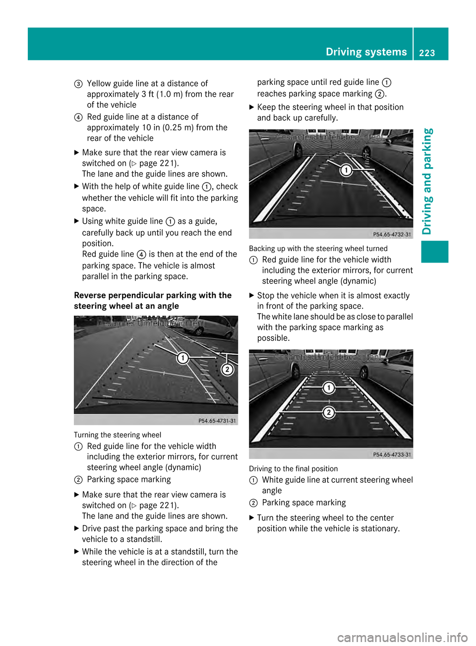
0023
Yellow guide line at a distance of
approximately 3 ft (1.0 m) from the rear
of the vehicle
0022 Red guide line at a distanc eof
approximately 10 in (0.25 m) from the
rear of the vehicle
X Make sure that the rear view camera is
switched on (Y page 221).
The lane and the guide lines are shown.
X With the help of white guide line 0002, check
whether the vehicle will fit into the parking
space.
X Using white guide line 0002as a guide,
carefully back up until you reach the end
position.
Red guide line 0022is then at the end of the
parking space. The vehicle is almost
parallel in the parking space.
Reverse perpendicular parking with the
steering wheel at an angle Turning the steering wheel
0002
Red guide line for the vehicle width
including the exterior mirrors, for current
steering wheel angle (dynamic)
0003 Parking space marking
X Make sure that the rear view camera is
switched on (Y page 221).
The lane and the guide lines are shown.
X Drive past the parking space and bring the
vehicle to a standstill.
X While the vehicle is at a standstill, tur nthe
steering wheel in the direction of the parking space until red guide line
0002
reaches parking space marking 0003.
X Keep the steering wheel in that position
and back up carefully. Backing up with the steering wheel turned
0002
Red guide line for the vehicle width
including the exterior mirrors, for current
steering wheel angle (dynamic)
X Stop the vehicle when it is almost exactly
in front of the parking space.
The white lane should be as close to parallel
with the parking space marking as
possible. Driving to the final position
0002
White guide line at current steering wheel
angle
0003 Parking space marking
X Turn the steering wheel to the center
position while the vehicle is stationary. Driving systems
223Driving and parking Z
Page 227 of 462
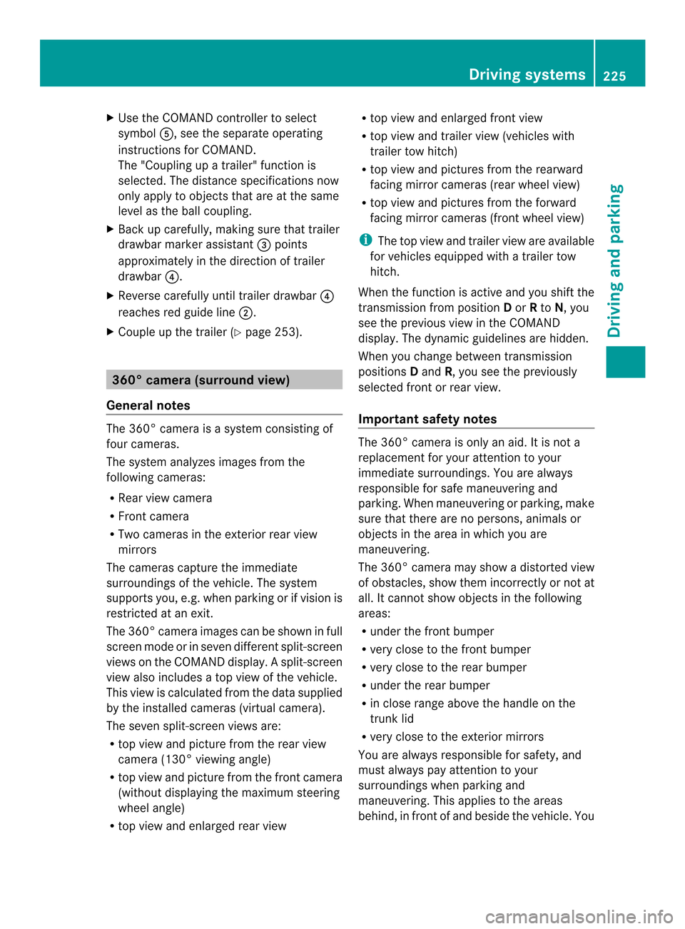
X
Use the COMAND controller to select
symbol 0020, see the separate operating
instructions for COMAND.
The "Coupling up a trailer" function is
selected. The distance specifications now
only apply to objects that are at the same
level as the ball coupling.
X Back up carefully, making sure that trailer
drawbarm arker assistant 0023points
approximately in the direction of trailer
drawbar 0022.
X Reverse carefully until trailer drawbar 0022
reaches red guide line 0003.
X Couple up the trailer (Y page 253).360° camera (surround view)
General notes The 360° camera is a system consisting of
four cameras.
The system analyzes images from the
following cameras:
R Rear view camera
R Front camera
R Two cameras in the exterior rear view
mirrors
The cameras capture the immediate
surroundings of the vehicle .The system
supports you, e.g. when parking or if vision is
restricted at an exit.
The 360° camera images can be shown in full
screen mode or in seven different split-screen
views on the COMAND display. Asplit-screen
view also includes a top view of the vehicle.
This view is calculated from the data supplied
by the installed cameras (virtual camera).
The seven split-screen views are:
R top view and picture from the rear view
camera (130 °viewing angle)
R top view and picture fro mthe front camera
(without displaying the maximum steering
wheel angle)
R top view and enlarged rear view R
top view and enlarged front view
R top view and trailer view (vehicles with
trailer tow hitch)
R top view and pictures from the rearward
facing mirror cameras (rear wheel view)
R top view and pictures from the forward
facing mirror cameras (front wheel view)
i The top view and trailer view are available
for vehicles equipped with a trailer tow
hitch.
When the function is active and you shift the
transmission from position Dor Rto N, you
see the previous view in the COMAND
display. The dynamic guidelines are hidden.
When you change between transmission
positions Dand R, you see the previously
selected front or rear view.
Important safety notes The 360° camera is only an aid. It is not a
replacement for your attention to your
immediate surroundings. You are always
responsible for safe maneuvering and
parking. When maneuvering or parking, make
sure that there are no persons, animals or
objects in the area in which you are
maneuvering.
The 360° camera may show a distorted view
of obstacles, show them incorrectly or not at
all. It cannot show objects in the following
areas:
R
under the front bumper
R very close to the front bumper
R very close to the rear bumper
R under the rear bumper
R in close range above the handle on the
trunk lid
R very close to the exterior mirrors
You are always responsible for safety, and
must always pay attention to your
surroundings when parking and
maneuvering. This applies to the areas
behind, in front of and beside the vehicle. You Driving systems
225Driving and parking Z
Page 228 of 462
could otherwise endanger yoursel
fand
others.
The 360° camera will not function or will
function in a limited manner:
R if the doors are open
R if the exterio rmirrors are folded in
R if the trunk lid is open
R in heavy rain, snow or fog
R at night or in very dark places
R if the cameras are exposed to very bright
light
R if the area is lit by fluorescen tlight or LED
lighting (the display may flicker)
R if you exit a heated garage in winter,
resulting in a rapid change in temperature
R if the camera lenses are dirty or covered
R if the vehicle components in which the
cameras are installed are damaged. In this
event, have the camera position and setting
checked at a qualified specialist workshop.
Do not use the 360 °camera in this case. You
can otherwise injure other sorcause damage
to objects or the vehicle.
Activation conditions The 360° camera image can be displayed if:
R
your vehicle is equipped with a 360°
camera
R COMAND is switched on, see the separate
COMAND operating instructions
R the 360° Camera function is activated
Activating the 360° camera using the
SYS button X
Press and hold the 0003button for longer
than 2seconds, see the separate COMAND
operating instructions.
Depending on whether position Dor Ris
engaged, the following is shown:
R full screen display with the image from
the front camera
R full screen display with the image from
the rear camera Activating the 360° camer
awith
COMAND X
Press the 0003button, see the separate
COMAN Doperating instructions.
X Select System by turning
000E0002000Fthe
COMAND controller and press 000Cto
confirm.
X Select 360° Camera and press
000Cto
confirm.
Depending on whether position Dor Ris
engaged, the following is shown:
R a split scree nwith top view and the
image from the front camera or
R a split screen with top view and the
image from the rear view camera
For further information about the COMAND
controller, see the separat eCOMAND
operating instructions.
Activating the 360° camera using
reverse gear The 360° camera images can be
automatically displayed by engaging reverse
gear.
X
Make sure that the SmartKey is in position
2in the ignition lock.
X Make sure that the Activation by R gear setting is active in COMAND, see the
separate COMAND operating instructions.
X To show the 360° camera image: engage
reverse gear.
The COMAND display shows the area
behind the vehicle in split screen:
R vehicle with guide lines
R top view of the vehicle
Selecting the split-screen and full
screen displays X
To switch between split screen views:
switch to the line with the vehicle icons by
sliding 000B0002the COMAND controller.
X Turn 000E0002000F the COMAND controller and
select one of the vehicle symbols. 226
Driving systemsDriving and parking
Page 229 of 462
X
To switc hto full screen mode: select
Full Screen by turning
000E0002000Fthe
COMAND controller and press 000Cto
confirm.
Displays in the COMAND display Important safety notes
!
Objects not at ground level may appear to
be further away than they actually are, e.g.:
R the bumper of a parked vehicle
R the drawbar of a trailer
R the ball coupling of a trailer tow hitch
R the rear section of an HGV
R a slanted post
Use the guidelines only for orientation.
Approach objects no further than the
bottom-mos tguideline.
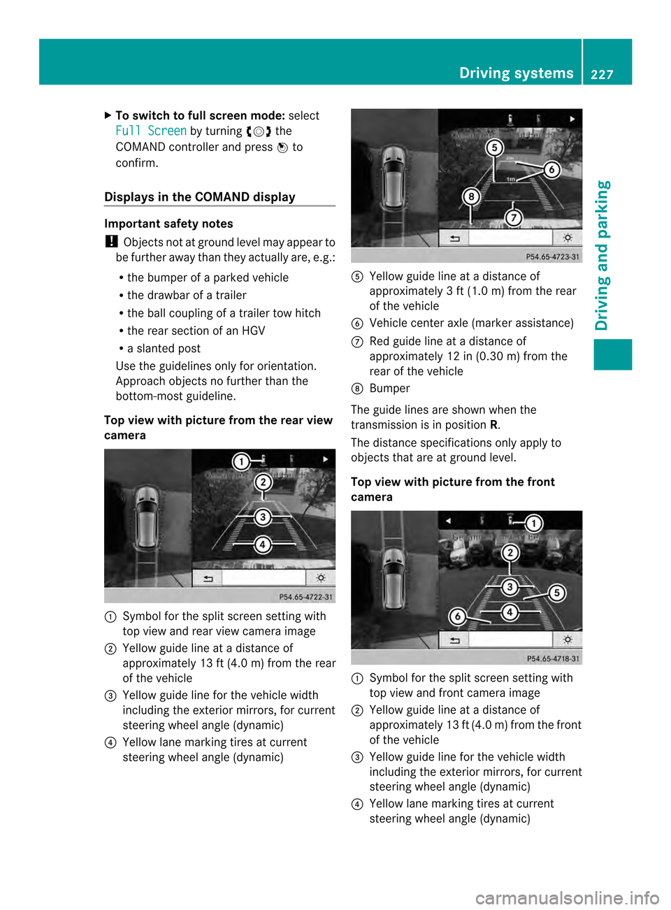
Top view with picture from the rear view
camera 0002
Symbol for the split scree nsetting with
top view and rear view camera image
0003 Yellow guide line at a distance of
approximately 13 ft (4.0 m) from the rear
of the vehicle
0023 Yellow guide line for the vehicle width
including the exterior mirrors, for current
steering wheel angle (dynamic)
0022 Yellow lane marking tires at current
steering wheel angle (dynamic) 0020
Yellow guide line at a distance of
approximately 3 ft (1.0 m) from the rear
of the vehicle
0021 Vehicle center axle (marker assistance)
0014 Red guide line at a distance of
approximately 12 in (0.30 m) from the
rear of the vehicle
0015 Bumper
The guide lines are show nwhen the
transmission is in position R.
The distance specifications only apply to
objects that are at ground level.
Top view with picture from the front
camera 0002
Symbol for the split screen setting with
top view and front camera image
0003 Yellow guide line at a distance of
approximately 13 ft (4.0 m) from the front
of the vehicle
0023 Yellow guide line for the vehicle width
including the exterior mirrors, for current
steering wheel angle (dynamic)
0022 Yellow lane marking tires at current
steering wheel angle (dynamic) Driving systems
227Driving and parking Z