change wheel MERCEDES-BENZ M-Class 2015 W166 Owner's Guide
[x] Cancel search | Manufacturer: MERCEDES-BENZ, Model Year: 2015, Model line: M-Class, Model: MERCEDES-BENZ M-Class 2015 W166Pages: 466, PDF Size: 8.92 MB
Page 255 of 466
The differential lock improves the vehicle's
traction. 4ETS (Y page 73) controls the bal-
ance between both wheels on an axle.
You can only activate off-road program 2
when driving at speeds of 25 mph (40 km/h)
or below.
LOW RANGE off-road gear (vehicles
with the ON&OFFROAD package) Important safety notes
G
WARNING
If you select the LOW RANGE off-road gear on a slippery road surface, the wheels could lose traction:
R if you remove your foot from the accelera-
tor pedal when driving
R if off road ABS intervenes when braking
If the wheels lose traction. the vehicle can no
longer be steered. There is an increased dan-
ger of skidding and accidents.
Never select the LOW RANGE off-road gear
when driving on slippery road surfaces. G
WARNING
If you do not wait for the transfer case gear
change process to complete, the transfer
case could remain in the neutral position. The power transmission to the driven wheels is
then interrupted. There is a danger of the
vehicle rolling away unintentionally. There is a
risk of an accident.
Wait until the transfer case shift process is
completed.
Do not turn off the engine while changing gear
and do not shift the automatic transmission
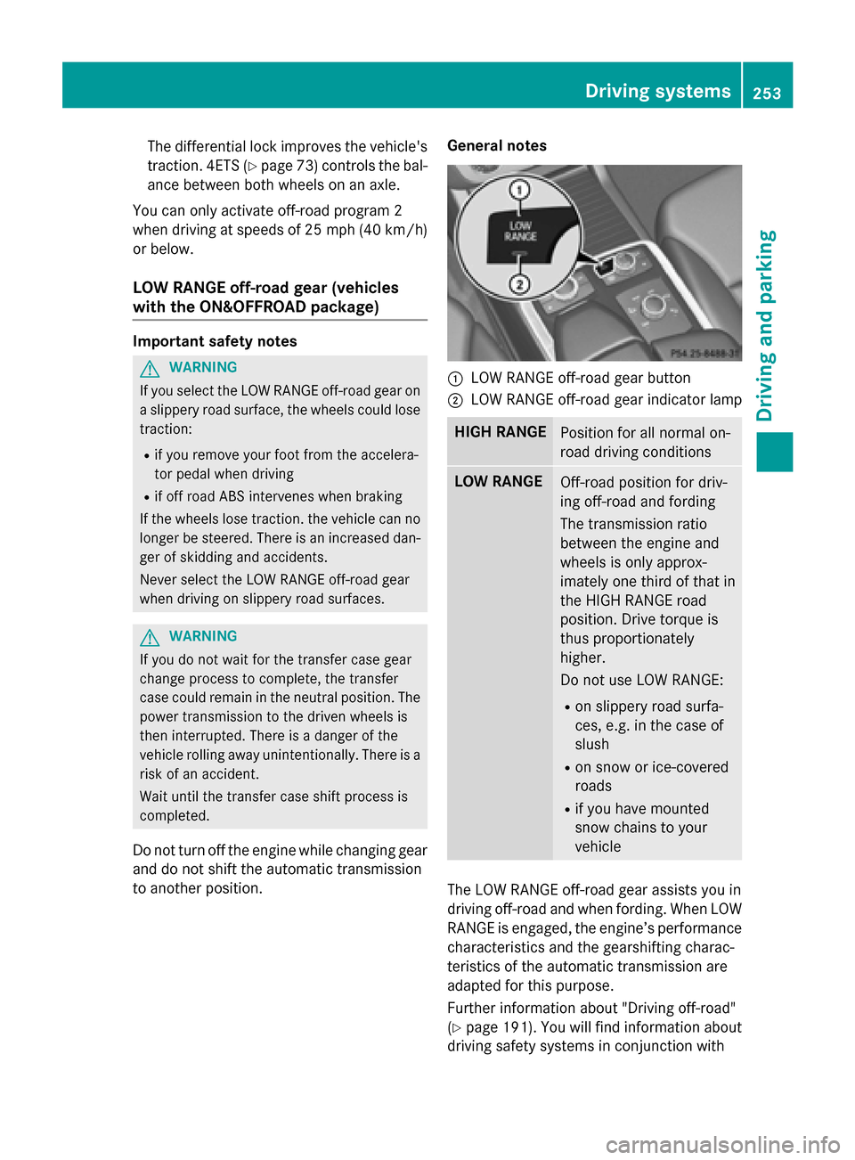
to another position. General notes 0043
LOW RANGE off-road gear button
0044 LOW RANGE off-road gear indicator lamp HIGH RANGE
Position for all normal on-
road driving conditions
LOW RANGE
Off-road position for driv-
ing off-road and fording
The transmission ratio
between the engine and
wheels is only approx-
imately one third of that in
the HIGH RANGE road
position. Drive torque is
thus proportionately
higher.
Do not use LOW RANGE:
R on slippery road surfa-
ces, e.g. in the case of
slush
R on snow or ice-covered
roads
R if you have mounted
snow chains to your
vehicle The LOW RANGE off-road gear assists you in
driving off-road and when fording. When LOW
RANGE is engaged, the engine’s performance
characteristics and the gearshifting charac-
teristics of the automatic transmission are
adapted for this purpose.
Further information about "Driving off-road"
(Y page 191). You will find information about
driving safety systems in conjunction with Driving systems
253Driving and parking Z
Page 257 of 466
Messages in the multifunction display
If a gear change process has not been successful, the following messages may be displayed in
the multifunction display: Display messages
Possible causes/consequences and
0050 0050Solutions LOW RANGE Max.
LOW RANGE Max.
Speed 40 km/h Speed 40 km/h You have been driving faster than 40 km/h. Additionally, the indi-
cator lamp on the button in the center console blinks.
X Drive more slowly to carry out the gear change process. LOW
LOW
RANGE
RANGE Shift
Shiftto
to
Position N Briefly
Position N Briefly The transmission is in position
Dand you are driving at below
40 km/h.
X Shift the transmission to Nto complete the gear change proc-
ess. LOW
LOW
RANGE
RANGE Shifting
Shifting
Canceled Please
Canceled Please
Reactivate Reactivate The gear change process was not carried out.
X Ensure that all gear change conditions are fulfilled and carry out
the gear change process again. LOW RANGE Stop
LOW RANGE Stop
Apply Apply
Parking
Parking Brake
Brake A warning tone also sounds. The gear change process has not been
completed. LOW RANGE is in the neutral position. There is no
connection between the engine and the drive wheels.
! Do not drive any further. You could otherwise damage the
vehicle's drive train.
X Stop the vehicle. Take into account the road and traffic condi-
tions when doing this.
X Depress the electric parking brake (Y page 184).
X Carry out the gear change process again.
If the gear change process has been carried out, the LOW LOWRANGE
RANGE
Stop Apply Parking Brake
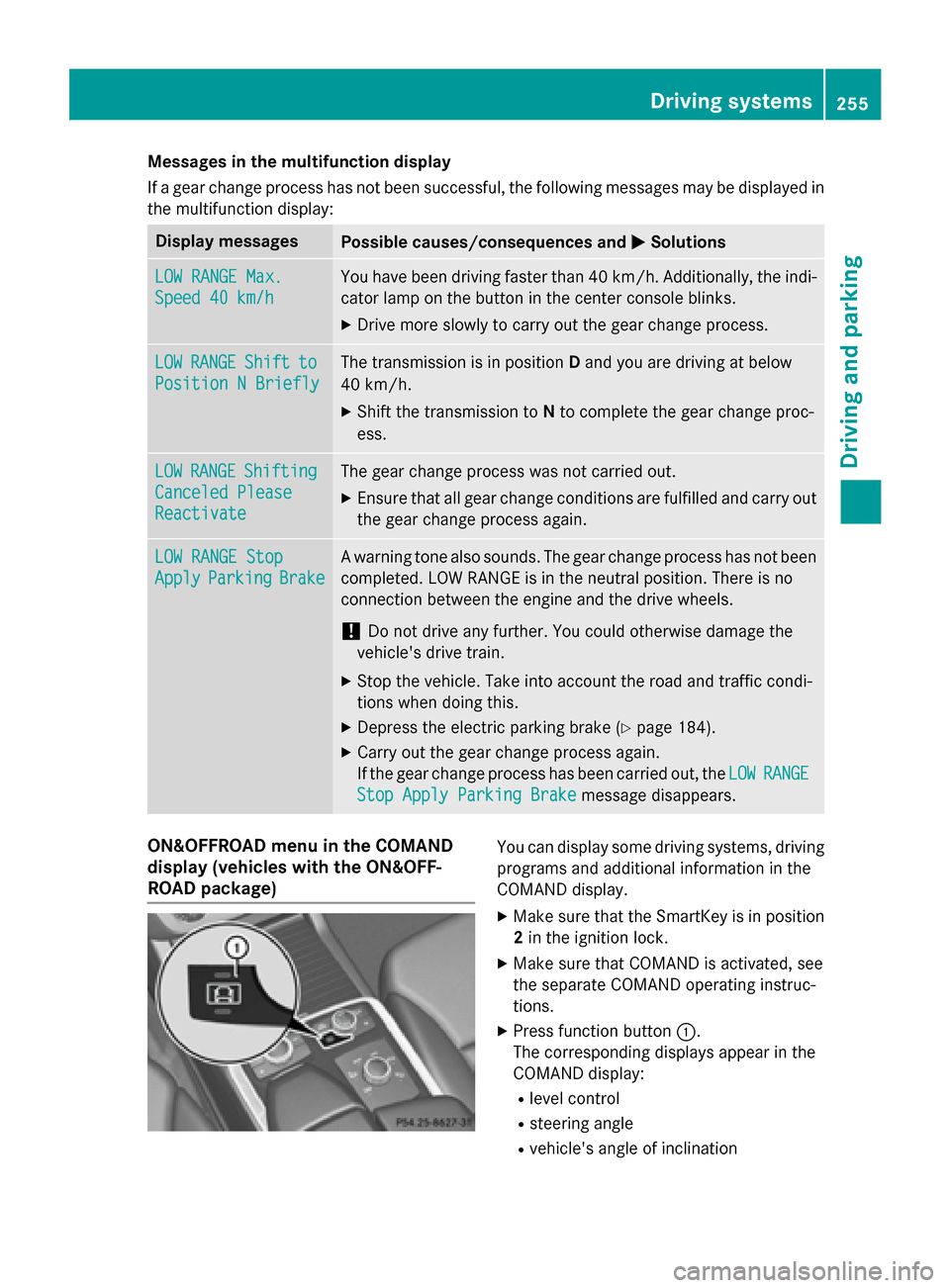
Stop Apply Parking Brake message disappears.ON&OFFROAD menu in the COMAND
display (vehicles with the ON&OFF-
ROAD package) You can display some driving systems, driving
programs and additional information in the
COMAND display.
X Make sure that the SmartKey is in position
2 in the ignition lock.
X Make sure that COMAND is activated, see
the separate COMAND operating instruc-
tions.
X Press function button 0043.
The corresponding displays appear in the
COMAND display:
R level control
R steering angle
R vehicle's angle of inclination Driving systems
255Driving and parking Z
Page 263 of 466
using the brake controller and check
whether the brakes function correctly.
R Secure any objects on the trailer to prevent
the cargo from slipping when the vehicle is
in motion.
R When you couple up a trailer, check at reg-
ular intervals that the load is firmly secured.If the trailer is equipped with trailer lights
and brakes, check the trailer to ensure that
these are working.
R Bear in mind that the handling will be less
stable when towing a trailer than when driv- ing without one. Avoid sudden steering
movements.
R The vehicle/trailer combination is heavier,
accelerates more slowly, has a decreased
gradient climbing capability and a longer
braking distance.
It is more susceptible to side winds and
requires more careful steering.
R If possible, do not brake suddenly, but
instead depress the brake pedal moder-
ately at first so that the trailer can activate its brakes. Then increase the pressure on
the brake pedal.
R If the automatic transmission repeatedly
shifts between gears on uphill or downhill
gradients, shift to a lower gear using the
left-hand steering wheel paddle shifter.
A lower gear and lower speed reduce the
risk of engine failure.
R When driving downhill, shift to a lower gear
to utilize the engine's braking effect.
Avoid continuous brake application as this
may overheat the vehicle brakes and, if
installed, the trailer brakes.
R If the coolant temperature increases dra-
matically while the air-conditioning system
is switched on, switch off the air-condition-
ing system.
Coolant heat can also be dissipated by
opening the windows and switching the ventilation blower and the interior temper-
ature to the highest level.
R When overtaking, pay particular attention
to the extended length of your vehicle/
trailer combination.
Due to the length of the vehicle/trailer
combination, you require additional road
space in relation to the vehicle you are
overtaking before you can change back to
the original lane. Decoupling a trailer
G
WARNING
If you uncouple a trailer with the overrun
brake engaged, you could trap your hand
between the vehicle and the trailer drawbar.
There is a risk of injury.
Do not uncouple a trailer if the overrun brake is engaged. G
WARNING
Vehicles with level control:
The vehicle is lowered as soon as you discon-
nect the trailer cable. This could result in your limbs or those of other people that are
between the vehicle body and tires or under-
neath the vehicle being trapped. There is a
risk of injury.
Make sure that nobody is in the immediate
vicinity of the wheel housings or under the
vehicle when you disconnect the trailer cable.
! Do not disconnect a trailer with an
engaged overrun brake. Otherwise, your
vehicle could be damaged by the rebound- ing of the overrun brake.
X Make sure that the automatic transmission
is set to position P.
X Apply the vehicle's electric parking brake.
X Start the engine.
X Close all doors and the tailgate.
X Apply the trailer's parking brake. Towing a trailer
261Driving and parking Z
Page 269 of 466
The coolant temperature gauge is in the
instrument cluster on the right-hand side
(Y page 35).
Under normal operating conditions and with
the specified coolant level, the coolant tem-
perature may rise to 248 ‡ (120 †). Tachometer
! Do not drive in the overrevving range, as
this could damage the engine.
The red band in the tachometer indicates the
engine's overrevving range.
The fuel supply is interrupted to protect the
engine when the red band is reached. Outside temperature display
You should pay special attention to road con-
ditions when temperatures are around freez-
ing point.
Bear in mind that the outside temperature
display indicates the temperature measured
and does not record the road temperature.
The outside temperature display is in the mul- tifunction display (Y page 268).
Changes in the outside temperature are dis-
played after a short delay. Speedometer with segments
The segments in the speedometer indicate
which speed range is available.
R Cruise control activated (Y page 195):
The segments light up from the stored
speed to the maximum speed.
R DISTRONIC PLUS activated (Y page 198):
One or two segments in the set speed
range light up.
R DISTRONIC PLUS detects a vehicle in front:
The segments between the speed of the
vehicle in front and the stored speed light
up. Operating the on-board computer
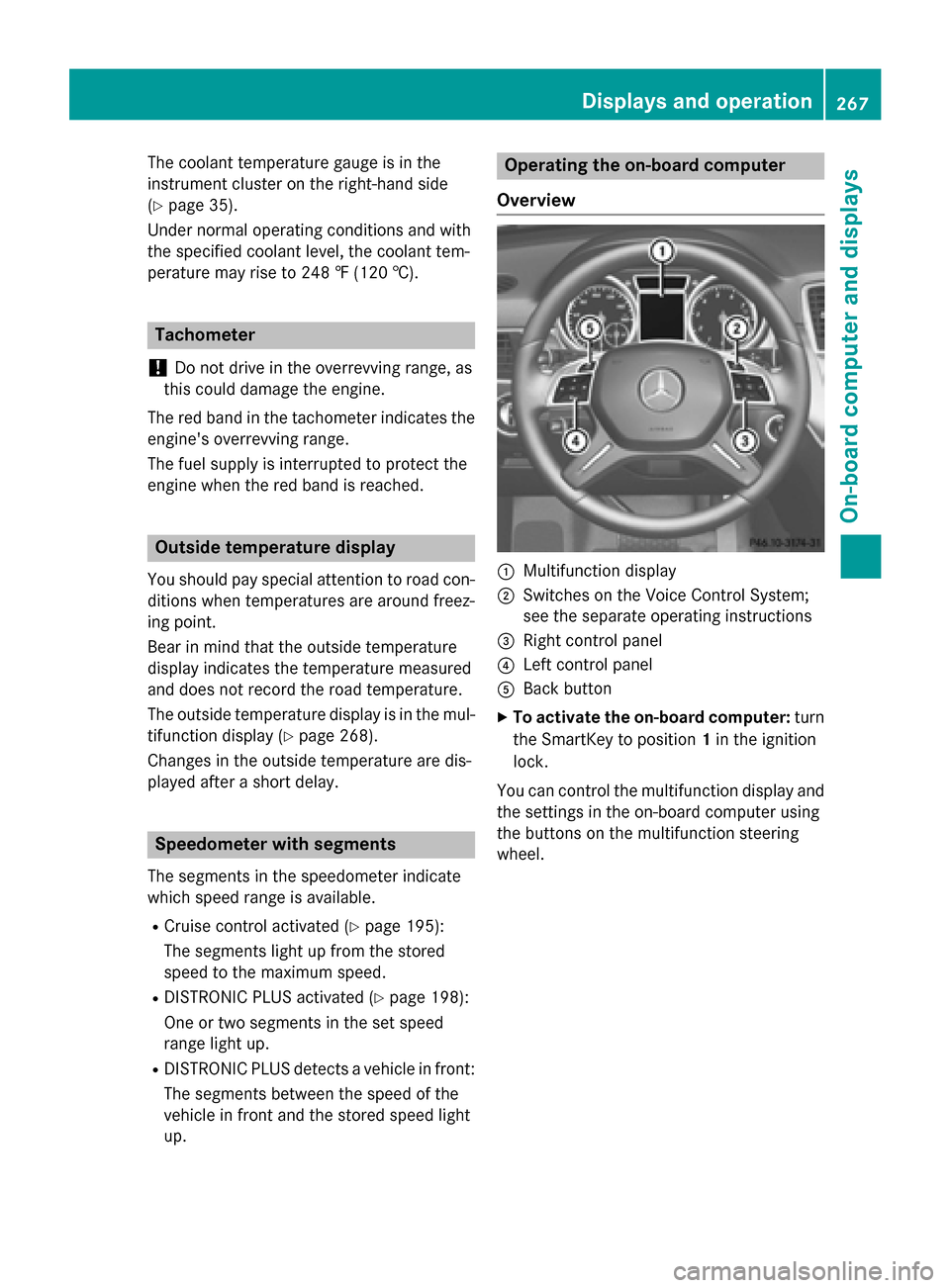
Overview 0043
Multifunction display
0044 Switches on the Voice Control System;
see the separate operating instructions
0087 Right control panel
0085 Left control panel
0083 Back button
X To activate the on-board computer: turn
the SmartKey to position 1in the ignition
lock.
You can control the multifunction display and
the settings in the on-board computer using
the buttons on the multifunction steering
wheel. Displays and operation
267On-board computer and displays Z
Page 273 of 466
X
Press the 0076button.
X Press the 0064button to select Yes
Yesand
press the 0076button to confirm.
You can reset the values of the following func-
tions:
R Trip odometer
R "From Start" trip computer
R "From Reset" trip computer
R ECO display
i If you reset the values in the ECO display,
the values in the "From start" trip computer are also reset. If you reset the values in the
"From start" trip computer, the values in
the ECO display are also reset. Navigation system menu
Displaying navigation instructions In the
Navi
Navimenu, the multifunction display
shows navigation instructions.
For more information, see the separate oper-
ating instructions.
X Switch on the audio system with Becker ®
MAP PILOT or COMAND; see the separate
operating instructions.
X Press the 0059or0065 button on the steer-
ing wheel to select the Navi Navimenu.
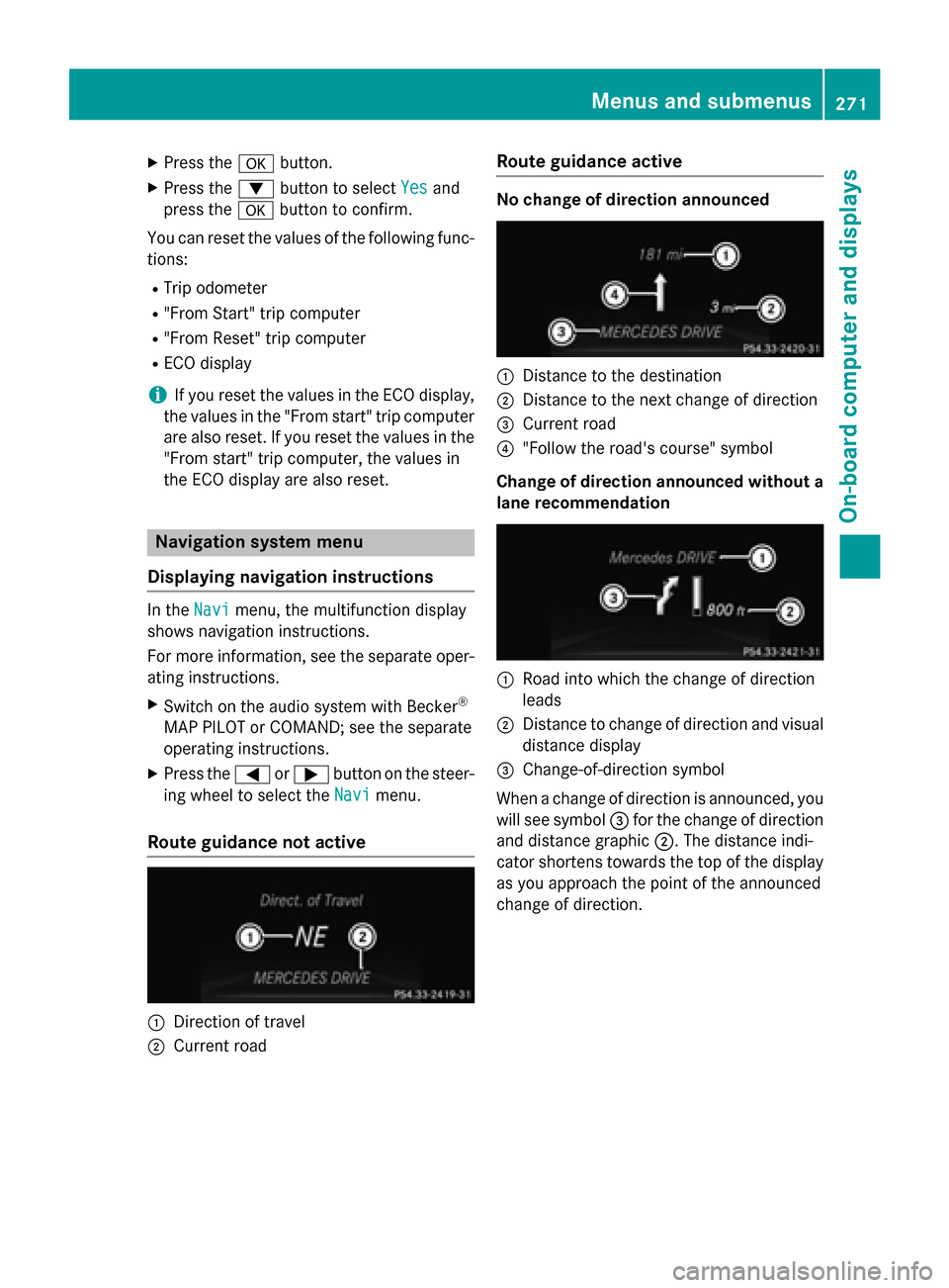
Route guidance not active 0043
Direction of travel
0044 Current road Route guidance active No change of direction announced
0043
Distance to the destination
0044 Distance to the next change of direction
0087 Current road
0085 "Follow the road's course" symbol
Change of direction announced without a lane recommendation 0043
Road into which the change of direction
leads
0044 Distance to change of direction and visual
distance display
0087 Change-of-direction symbol
When a change of direction is announced, you
will see symbol 0087for the change of direction
and distance graphic 0044. The distance indi-
cator shortens towards the top of the display
as you approach the point of the announced
change of direction. Menus and submenus
271On-board computer and displays Z
Page 274 of 466
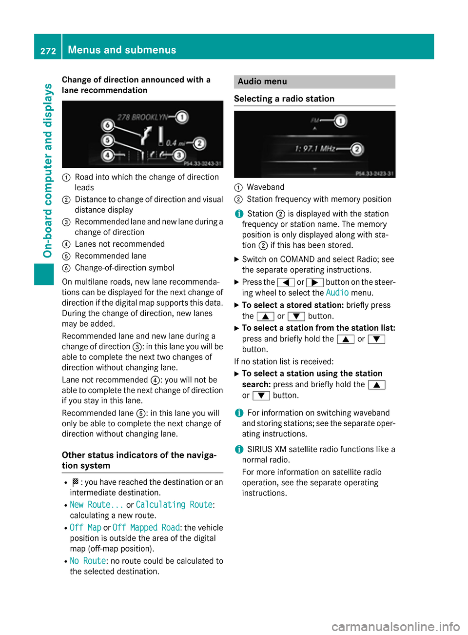
Change of direction announced with a
lane recommendation 0043
Road into which the change of direction
leads
0044 Distance to change of direction and visual
distance display
0087 Recommended lane and new lane during a
change of direction
0085 Lanes not recommended
0083 Recommended lane
0084 Change-of-direction symbol
On multilane roads, new lane recommenda-
tions can be displayed for the next change of
direction if the digital map supports this data.
During the change of direction, new lanes
may be added.
Recommended lane and new lane during a
change of direction 0087: in this lane you will be
able to complete the next two changes of
direction without changing lane.
Lane not recommended 0085: you will not be
able to complete the next change of direction
if you stay in this lane.
Recommended lane 0083: in this lane you will
only be able to complete the next change of
direction without changing lane.
Other status indicators of the naviga-
tion system R
004B: you have reached the destination or an
intermediate destination.
R New Route... New Route... orCalculating Route
Calculating Route:
calculating a new route.
R Off Map
Off Map orOff
Off Mapped
Mapped Road
Road: the vehicle
position is outside the area of the digital
map (off-map position).
R No Route
No Route : no route could be calculated to
the selected destination. Audio menu
Selecting a radio station 0043
Waveband
0044 Station frequency with memory position
i Station
0044is displayed with the station
frequency or station name. The memory
position is only displayed along with sta-
tion 0044if this has been stored.
X Switch on COMAND and select Radio; see
the separate operating instructions.
X Press the 0059or0065 button on the steer-
ing wheel to select the Audio
Audio menu.
X To select a stored station: briefly press
the 0063 or0064 button.
X To select a station from the station list:
press and briefly hold the 0063or0064
button.
If no station list is received: X To select a station using the station
search: press and briefly hold the 0063
or 0064 button.
i For information on switching waveband
and storing stations; see the separate oper-
ating instructions.
i SIRIUS XM satellite radio functions like a
normal radio.
For more information on satellite radio
operation, see the separate operating
instructions. 272
Menus and submenusOn-board computer and displays
Page 275 of 466
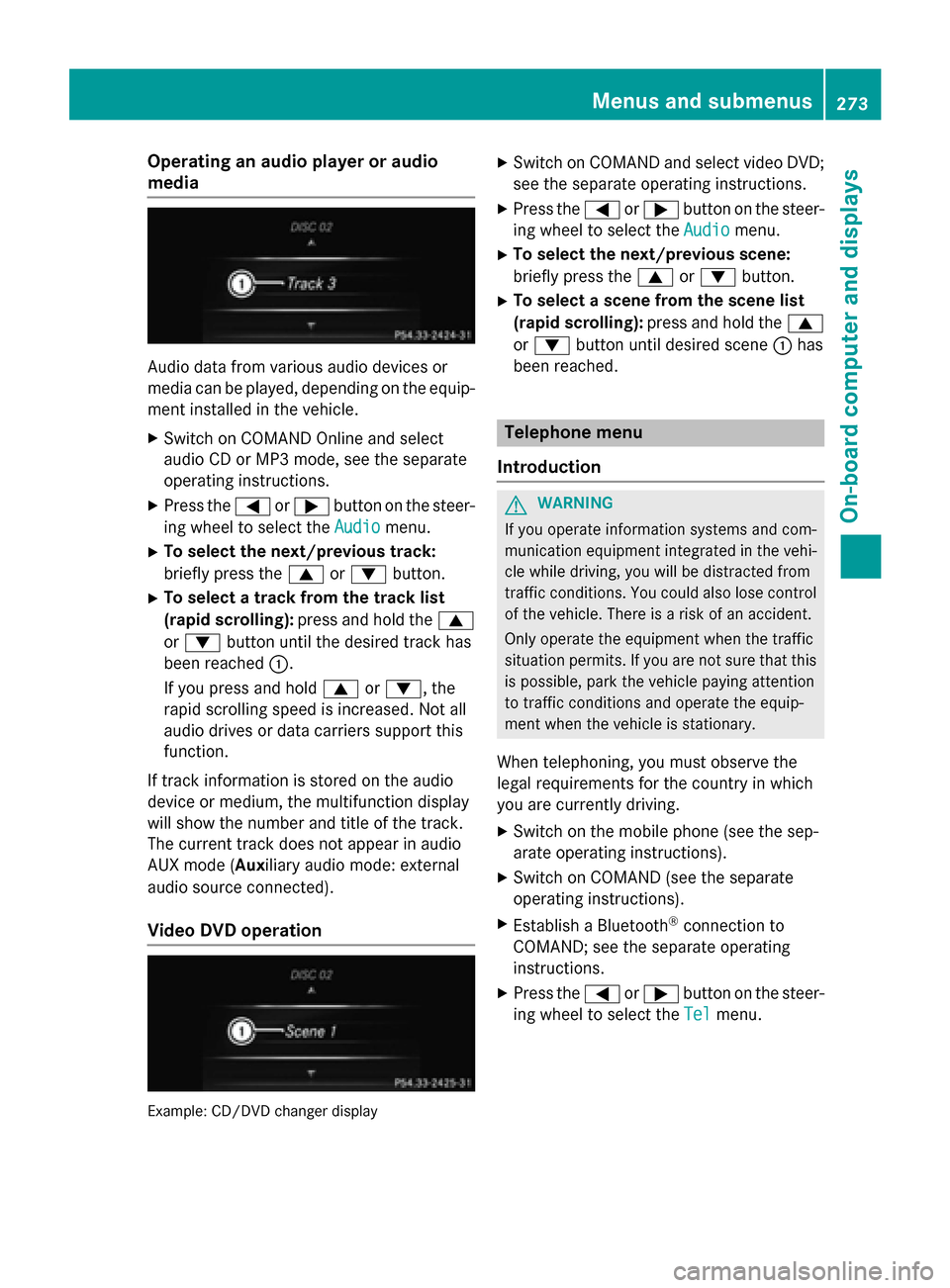
Operating an audio player or audio
media Audio data from various audio devices or
media can be played, depending on the equip- ment installed in the vehicle.
X Switch on COMAND Online and select
audio CD or MP3 mode, see the separate
operating instructions.
X Press the 0059or0065 button on the steer-
ing wheel to select the Audio
Audio menu.
X To select the next/previous track:
briefly press the 0063or0064 button.
X To select a track from the track list
(rapid scrolling): press and hold the 0063
or 0064 button until the desired track has
been reached 0043.
If you press and hold 0063or0064, the
rapid scrolling speed is increased. Not all
audio drives or data carriers support this
function.
If track information is stored on the audio
device or medium, the multifunction display
will show the number and title of the track.
The current track does not appear in audio
AUX mode (Aux iliary audio mode: external
audio source connected).
Video DVD operation Example: CD/DVD changer display X
Switch on COMAND and select video DVD;
see the separate operating instructions.
X Press the 0059or0065 button on the steer-
ing wheel to select the Audio
Audio menu.
X To select the next/previous scene:
briefly press the 0063or0064 button.
X To select a scene from the scene list
(rapid scrolling): press and hold the 0063
or 0064 button until desired scene 0043has
been reached. Telephone menu
Introduction G
WARNING
If you operate information systems and com-
munication equipment integrated in the vehi- cle while driving, you will be distracted from
traffic conditions. You could also lose control of the vehicle. There is a risk of an accident.
Only operate the equipment when the traffic
situation permits. If you are not sure that this
is possible, park the vehicle paying attention
to traffic conditions and operate the equip-
ment when the vehicle is stationary.
When telephoning, you must observe the
legal requirements for the country in which
you are currently driving.
X Switch on the mobile phone (see the sep-
arate operating instructions).
X Switch on COMAND (see the separate
operating instructions).
X Establish a Bluetooth ®
connection to
COMAND; see the separate operating
instructions.
X Press the 0059or0065 button on the steer-
ing wheel to select the Tel Telmenu. Menus and submenus
273On-board computer and displays Z
Page 308 of 466
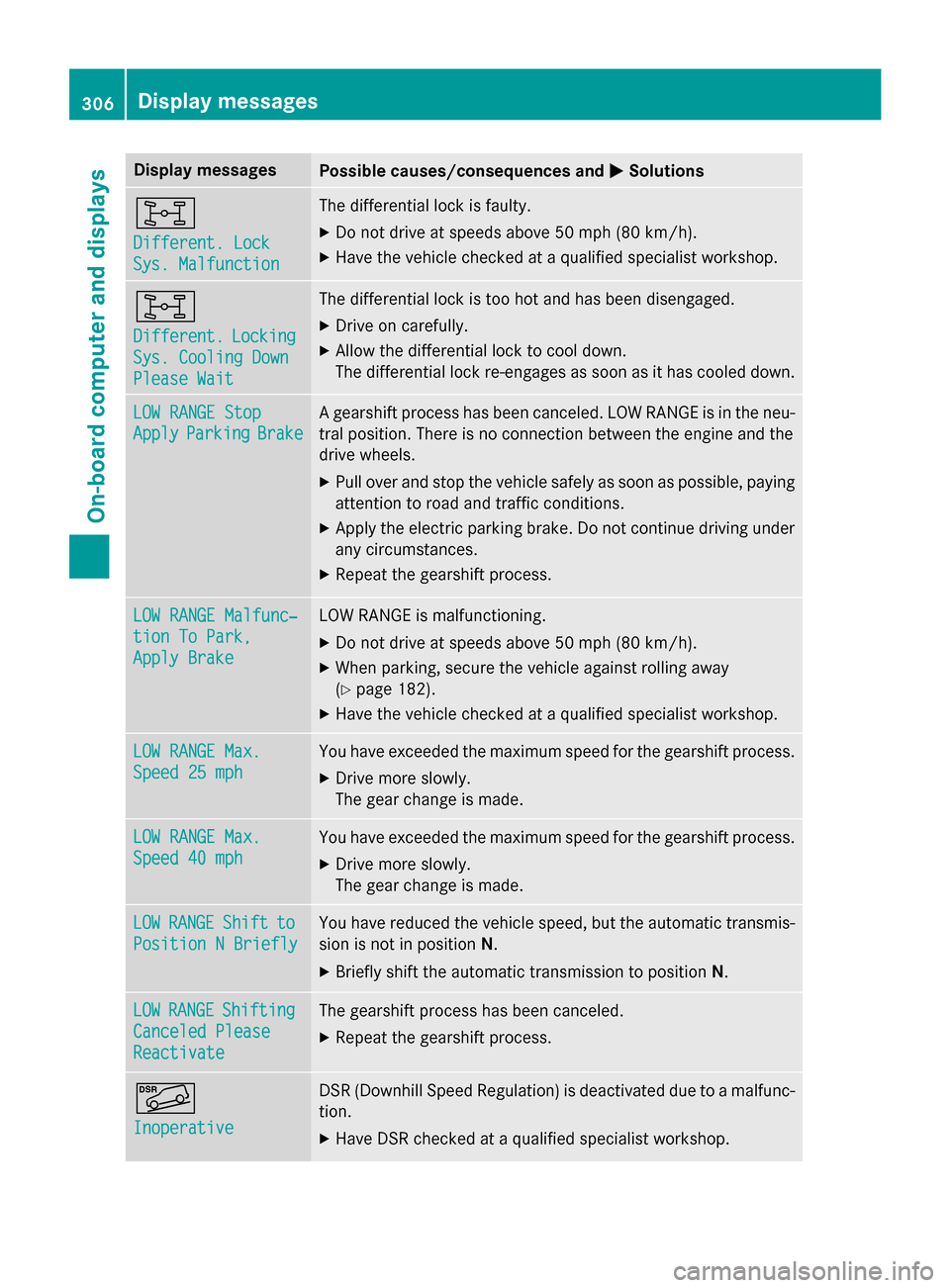
Display messages
Possible causes/consequences and
0050
0050Solutions 00F6
Different. Lock Different. Lock
Sys. Malfunction Sys. Malfunction The differential lock is faulty.
X Do not drive at speeds above 50 mph (80 km/h).
X Have the vehicle checked at a qualified specialist workshop. 00F6
Different. Different.
Locking
Locking
Sys. Cooling Down
Sys. Cooling Down
Please Wait Please Wait The differential lock is too hot and has been disengaged.
X Drive on carefully.
X Allow the differential lock to cool down.
The differential lock re-engages as soon as it has cooled down. LOW RANGE Stop LOW RANGE Stop
Apply Apply
Parking
Parking Brake
Brake A gearshift process has been canceled. LOW RANGE is in the neu-
tral position. There is no connection between the engine and the
drive wheels.
X Pull over and stop the vehicle safely as soon as possible, paying
attention to road and traffic conditions.
X Apply the electric parking brake. Do not continue driving under
any circumstances.
X Repeat the gearshift process. LOW RANGE Malfunc‐
LOW RANGE Malfunc‐
tion To Park, tion To Park,
Apply Brake Apply Brake LOW RANGE is malfunctioning.
X Do not drive at speeds above 50 mph (80 km/h).
X When parking, secure the vehicle against rolling away
(Y page 182).
X Have the vehicle checked at a qualified specialist workshop. LOW RANGE Max. LOW RANGE Max.
Speed 25 mph Speed 25 mph You have exceeded the maximum speed for the gearshift process.
X Drive more slowly.
The gear change is made. LOW RANGE Max. LOW RANGE Max.
Speed 40 mph Speed 40 mph You have exceeded the maximum speed for the gearshift process.
X Drive more slowly.
The gear change is made. LOW LOW
RANGE
RANGE Shift
Shiftto
to
Position N Briefly
Position N Briefly You have reduced the vehicle speed, but the automatic transmis-
sion is not in position N.
X Briefly shift the automatic transmission to position N.LOW
LOW
RANGE
RANGE Shifting
Shifting
Canceled Please
Canceled Please
Reactivate Reactivate The gearshift process has been canceled.
X Repeat the gearshift process. 00C6
Inoperative Inoperative DSR (Downhill Speed Regulation) is deactivated due to a malfunc-
tion.
X Have DSR checked at a qualified specialist workshop. 306
Display
messagesOn-board computer and displays
Page 314 of 466
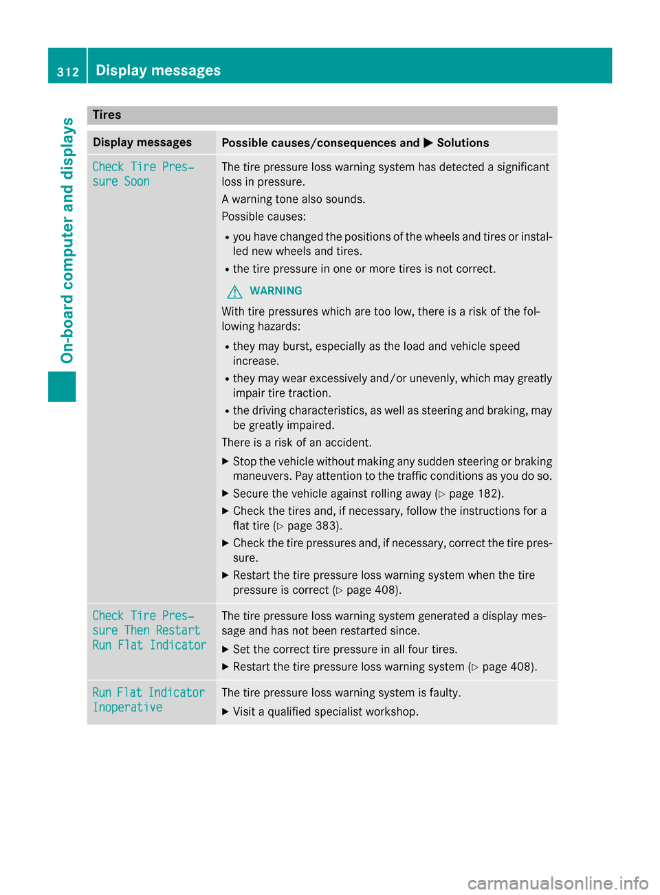
Tires
Display messages
Possible causes/consequences and
0050
0050Solutions Check Tire Pres‐
Check Tire Pres‐
sure Soon sure Soon The tire pressure loss warning system has detected a significant
loss in pressure.
A warning tone also sounds.
Possible causes:
R you have changed the positions of the wheels and tires or instal-
led new wheels and tires.
R the tire pressure in one or more tires is not correct.
G WARNING
With tire pressures which are too low, there is a risk of the fol-
lowing hazards:
R they may burst, especially as the load and vehicle speed
increase.
R they may wear excessively and/or unevenly, which may greatly
impair tire traction.
R the driving characteristics, as well as steering and braking, may
be greatly impaired.
There is a risk of an accident.
X Stop the vehicle without making any sudden steering or braking
maneuvers. Pay attention to the traffic conditions as you do so.
X Secure the vehicle against rolling away (Y page 182).
X Check the tires and, if necessary, follow the instructions for a
flat tire (Y page 383).
X Check the tire pressures and, if necessary, correct the tire pres-
sure.
X Restart the tire pressure loss warning system when the tire
pressure is correct (Y page 408).Check Tire Pres‐ Check Tire Pres‐
sure Then Restart sure Then Restart
Run Flat Indicator Run Flat Indicator The tire pressure loss warning system generated a display mes-
sage and has not been restarted since.
X Set the correct tire pressure in all four tires.
X Restart the tire pressure loss warning system (Y page 408).Run Run
Flat
Flat Indicator
Indicator
Inoperative
Inoperative The tire pressure loss warning system is faulty.
X Visit a qualified specialist workshop. 312
Display
messagesOn-board computer and displays
Page 336 of 466
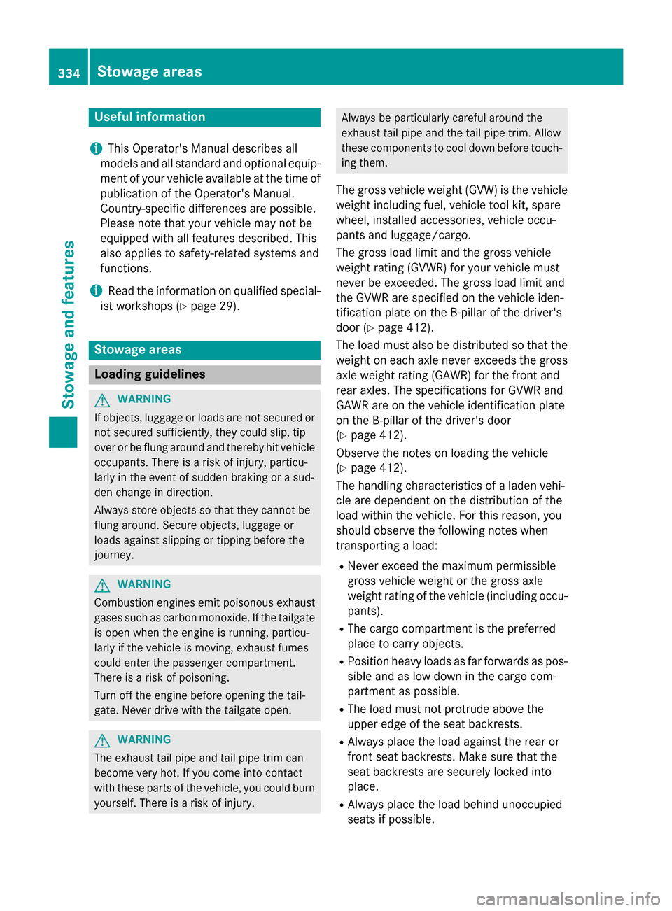
Useful information
i This Operator's Manual describes all
models and all standard and optional equip- ment of your vehicle available at the time of
publication of the Operator's Manual.
Country-specific differences are possible.
Please note that your vehicle may not be
equipped with all features described. This
also applies to safety-related systems and
functions.
i Read the information on qualified special-
ist workshops (Y page 29). Stowage areas
Loading guidelines
G
WARNING
If objects, luggage or loads are not secured or not secured sufficiently, they could slip, tip
over or be flung around and thereby hit vehicle
occupants. There is a risk of injury, particu-
larly in the event of sudden braking or a sud-
den change in direction.
Always store objects so that they cannot be
flung around. Secure objects, luggage or
loads against slipping or tipping before the
journey. G
WARNING
Combustion engines emit poisonous exhaust
gases such as carbon monoxide. If the tailgate is open when the engine is running, particu-
larly if the vehicle is moving, exhaust fumes
could enter the passenger compartment.
There is a risk of poisoning.
Turn off the engine before opening the tail-
gate. Never drive with the tailgate open. G
WARNING
The exhaust tail pipe and tail pipe trim can
become very hot. If you come into contact
with these parts of the vehicle, you could burn
yourself. There is a risk of injury. Always be particularly careful around the
exhaust tail pipe and the tail pipe trim. Allow
these components to cool down before touch-
ing them.
The gross vehicle weight (GVW) is the vehicle
weight including fuel, vehicle tool kit, spare
wheel, installed accessories, vehicle occu-
pants and luggage/cargo.
The gross load limit and the gross vehicle
weight rating (GVWR) for your vehicle must
never be exceeded. The gross load limit and
the GVWR are specified on the vehicle iden-
tification plate on the B-pillar of the driver's
door (Y page 412).
The load must also be distributed so that the
weight on each axle never exceeds the gross axle weight rating (GAWR) for the front and
rear axles. The specifications for GVWR and
GAWR are on the vehicle identification plate
on the B-pillar of the driver's door
(Y page 412).
Observe the notes on loading the vehicle
(Y page 412).
The handling characteristics of a laden vehi-
cle are dependent on the distribution of the
load within the vehicle. For this reason, you
should observe the following notes when
transporting a load:
R Never exceed the maximum permissible
gross vehicle weight or the gross axle
weight rating of the vehicle (including occu-
pants).
R The cargo compartment is the preferred
place to carry objects.
R Position heavy loads as far forwards as pos-
sible and as low down in the cargo com-
partment as possible.
R The load must not protrude above the
upper edge of the seat backrests.
R Always place the load against the rear or
front seat backrests. Make sure that the
seat backrests are securely locked into
place.
R Always place the load behind unoccupied
seats if possible. 334
Stowage areasStowage and features