battery MERCEDES-BENZ METRIS 2016 MY16 Operator’s Manual
[x] Cancel search | Manufacturer: MERCEDES-BENZ, Model Year: 2016, Model line: METRIS, Model: MERCEDES-BENZ METRIS 2016Pages: 310, PDF Size: 7.28 MB
Page 169 of 310
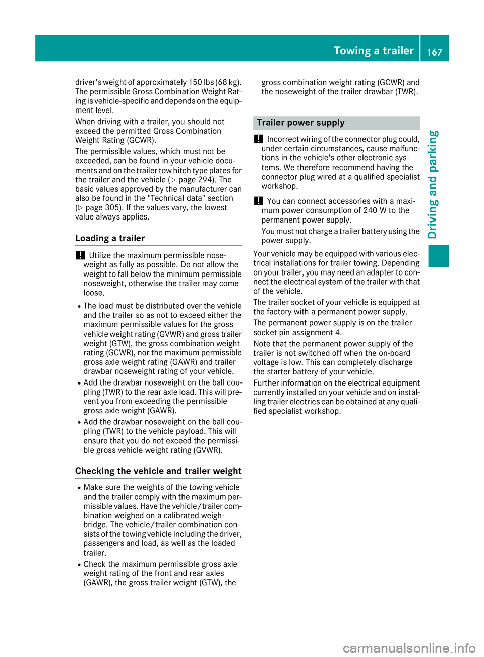
driver'sweight of approximately 150 lbs (68 kg).
The permissible Gross Combination Weight Rat-
ing is vehicle-specific and depends on the equip-
ment level.
When driving with atrailer, you should not
exceed the permitted Gross Combination
Weight Rating (GCWR).
The permissible values, which must not be
exceeded, can be found in your vehicle docu-
ment sand on the trailer tow hitc htype plates for
the trailer and the vehicle (
Ypage 294). The
basic values approved by the manufacturer can
also be found in the "Technical data" section
(
Ypage 305). If the values vary, the lowest
value always applies.
Loading atrailer
!Utiliz ethe maximum permissible nose-
weight as fully as possible. Do not allow the
weight to fall below the minimum permissible
noseweight ,otherwise the trailer may come
loose.
RThe load must be distributed over the vehicle
and the trailer so as not to exceed either the
maximum permissible values for the gross
vehicle weight ratin g(GVWR) and gross trailer
weight (GTW), the gross combination weight
ratin g(GCWR), nor the maximum permissible
gross axle weight ratin g(GAWR) and trailer
drawbar noseweight ratin gofyour vehicle.
RAdd the drawbar noseweight on the ball cou-
pling (TWR) to the rear axle load. This will pre-
vent you from exceeding the permissible
gross axle weight (GAWR).
RAdd the drawbar noseweight on the ball cou-
pling (TWR) to the vehicle payload. This will
ensure that you do not exceed the permissi-
ble gross vehicle weight ratin g(GVWR).
Checking the vehicle and trailer weight
RMake sure the weights of the towing vehicle
and the trailer comply with the maximum per-
missible values. Have the vehicle/trailer com-
bination weighed on acalibrated weigh-
bridge. The vehicle/trailer combination con-
sists of the towing vehicle includin gthe driver,
passenger sand load, as well as the loaded
trailer.
RCheck the maximum permissible gross axle
weight ratin gofthe fronta nd rear axles
(GAWR), the gross trailer weight (GTW), the gross combination weight ratin
g(GCWR) and
the noseweight of the trailer drawbar (TWR).
Trailer power supply
!
Incorrectw iring of the connector plug could,
under certain circumstances, cause malfunc-
tion sint he vehicle's other electronic sys-
tems .Wet herefore recommend having the
connector plug wired at aqualified specialist
workshop.
!You can connec taccessories with amaxi-
mum power consumption of 240 Wtothe
permanen tpower supply.
You must not charge atrailer battery using the
power supply.
Your vehicle may be equipped with various elec-
trical installations for trailer towing .Depending
on your trailer, you may need an adapter to con-
nec tthe electrical system of the trailer with that
of the vehicle.
The trailer socket of your vehicle is equipped at
the factory with apermanen tpower supply.
The permanen tpower supply is on the trailer
socket pin assignmen t4.
Note that the permanen tpower supply of the
trailer is not switched off when the on-board
voltage is low. This can completely discharge
the starter battery of your vehicle.
Further information on the electrical equipment currently installed on your vehicle and on instal-
ling trailer electrics can be obtained at any quali-
fied specialist workshop.
Towing atrailer167
Driving and parking
Z
Page 199 of 310
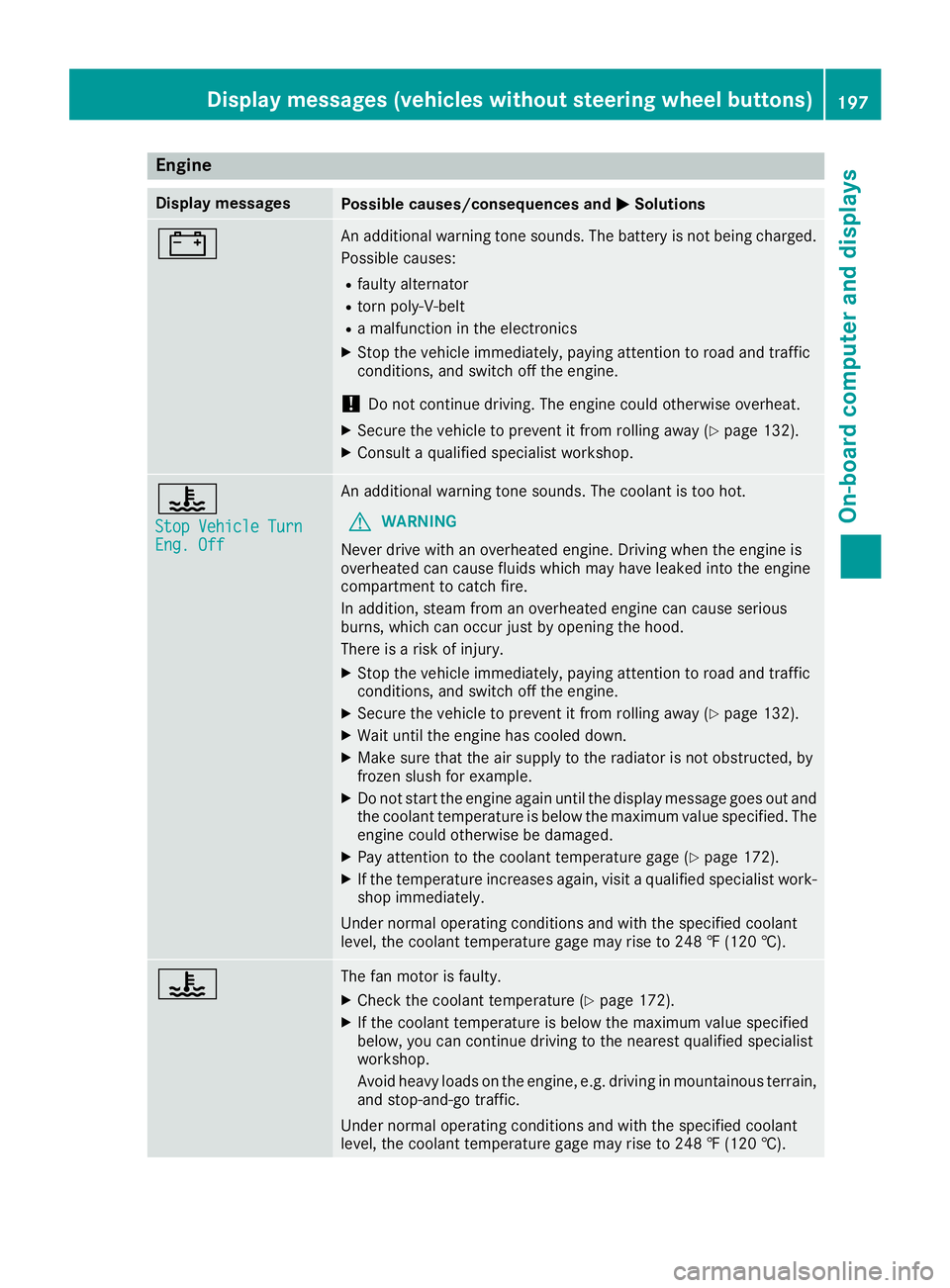
Engine
Display messagesPossible causes/consequences andMSolutions
#An additional warning tone sounds. The battery is no tbeingc harged.
Possible causes:
Rfault yalternator
Rtorn poly-V-belt
Ram alfunctio nintheelectronics
XStop th evehicle immediately, payinga ttention to road and traffic
conditions, and switch off th eengine.
!Do no tcontinue driving .The engine coul dotherwise overheat.
XSecure th evehicle to prevent it from rolling away (Ypage 132).
XConsult aqualified specialist workshop.
?
StopV ehicleT urnEng.Off
An additional warning tone sounds. The coolant is to ohot.
GWARNING
Never driv ewith an overheate dengine .Drivin gw hen th eengine is
overheate dcan caus efluids whichm ay have leaked int othe engine
compartmen ttocatch fire.
In addition,s team from an overheate dengine can caus eserious
burns, whichc an occur justbyopening th ehood.
Thereisar isk of injury.
XStop thevehicle immediately, payinga ttention to road and traffic
conditions, and switch off th eengine.
XSecure th evehicle to prevent it from rolling away (Ypage 132).
XWait until th eengine has cooled down.
XMakes ure that th eair supply to th eradiator is no tobstructed, by
frozen slush for example.
XDo no tstart th eengine again until th edisplay message goes out and
th ec oolant temperatur eisbelow th emaximum value specified. The
engine coul dotherwise be damaged.
XPay attention to th ecoolant temperatur egage (Ypage 172).
XIf th etem peratur eincreases again,v isitaq ualified specialist work-
shop immediately.
Under normal operatin gconditionsa nd with thespecifie dcoolant
level, th ecoolant temperatur egage may rise to 24 8‡(120† ).
?The fan motor is faulty.
XCheckt hecoolant temperatur e(Ypage 172).
XIf thecoolant temperatur eisbelow th emaximum value specified
below, you can continue driving to th enearest qualified specialist
workshop.
Avoid heavyl oads on theengine ,e.g.d riving in mountainous terrain,
and stop-and-go traffic.
Under normal operatin gconditionsa nd with thespecifie dcoolant
level, th ecoolant temperatur egage may rise to 24 8‡(120† ).
Displa ymessages (vehicles without steerin gwheel buttons)197
On-boardc omputer and displays
Z
Page 213 of 310
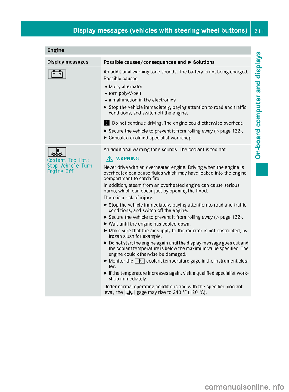
Engine
Display messagesPossible causes/consequences andMSolutions
#An additional warning tone sounds. The battery is no tbeingc harged.
Possible causes:
Rfault yalternator
Rtorn poly-V-belt
Ram alfunctio nintheelectronics
XStop th evehicle immediately, payinga ttention to road and traffic
conditions, and switch off th eengine.
!Do no tcontinue driving .The engine coul dotherwise overheat.
XSecure th evehicle to prevent it from rolling away (Ypage 132).
XConsult aqualified specialist workshop.
?
CoolantT oo Hot:StopVehicleT urnEngine Off
An additional warning tone sounds. The coolant is to ohot.
GWARNING
Never driv ewith an overheate dengine .Drivin gw hen th eengine is
overheate dcan caus efluids whichm ay have leaked int othe engine
compartmen ttocatch fire.
In addition,s team from an overheate dengine can caus eserious
burns, whichc an occur justbyopening th ehood.
Thereisar isk of injury.
XStop thevehicle immediately, payinga ttention to road and traffic
conditions, and switch off th eengine.
XSecure th evehicle to prevent it from rolling away (Ypage 132).
XWait until th eengine has cooled down.
XMakes ure that th eair supply to th eradiator is no tobstructed, by
frozen slush for example.
XDo no tstart th eengine again until th edisplay message goes out and
th ec oolant temperatur eisbelow th emaximum value specified. The
engine coul dotherwise be damaged.
XMonito rthe ? coolant temperatur egage in th einstrumen tclus-
ter.
XIf th etem peratur eincreases again,v isitaq ualified specialist work-
shop immediately.
Under normal operatin gconditionsa nd with thespecifie dcoolant
level, the ?gage may rise to 24 8‡(120† ).
Displa ymessages (vehicles with steerin gwheel buttons)211
On-boardc omputer and displays
Z
Page 219 of 310
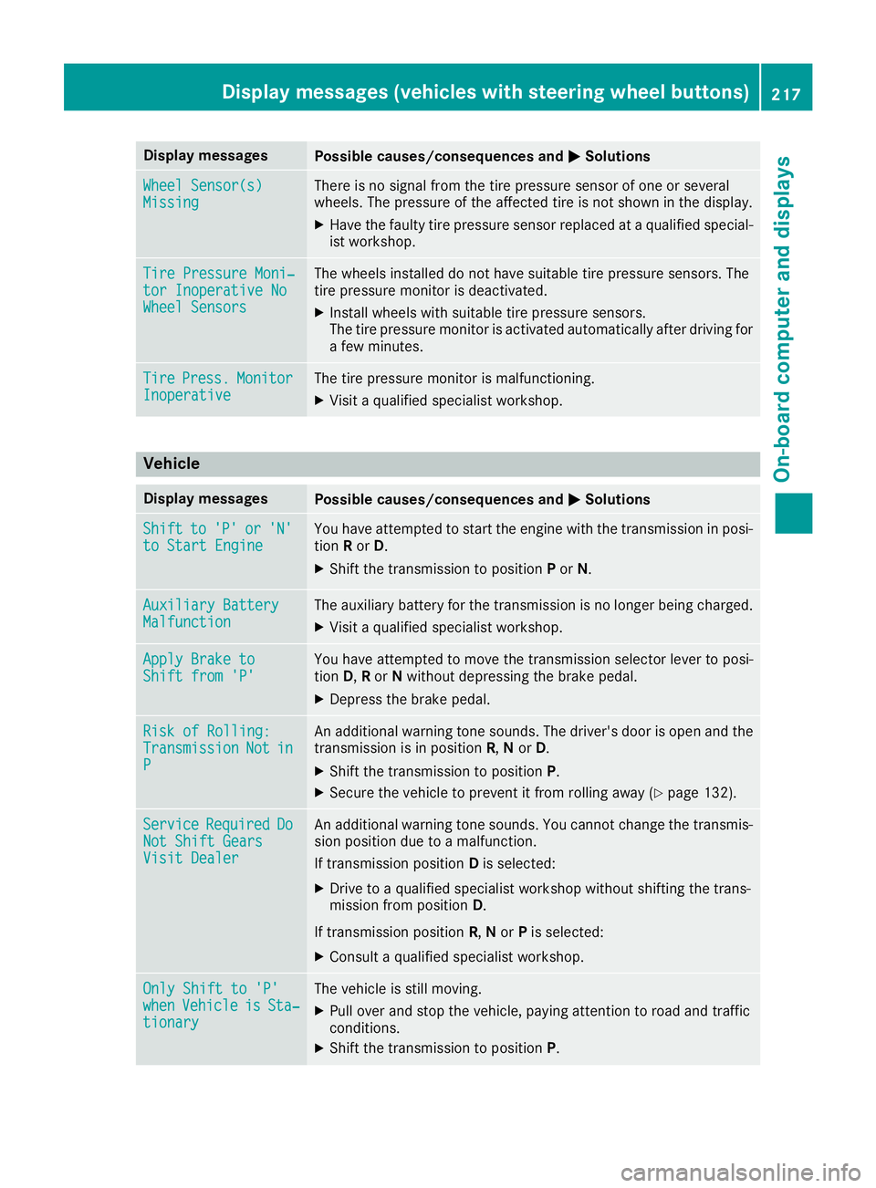
Display messagesPossible causes/consequences andMSolutions
Wheel Sensor(s)MissingThere is no signal from th etirep ressur esensor of on eorseveral
wheels. The pressur eoftheaffecte dtireisn otshown in th edisplay.
XHav ethe fault ytirep ressur esensor replace dataqualified special -
ist workshop .
TirePressure Moni‐tor Inoperative NoWheel Sensor s
The wheels installed do no thaves uitable tire pressur esensors. The
tire pressur emonitor is deactivated.
XInstall wheels wit hsuitable tire pressur esensors.
The tire pressur emonitor is activated automatically after drivin gfor
af ew minutes.
Tir ePress.Monito rInoperativeThe tire pressur emonitor is malfunctioning .
XVisitaqualified specialist workshop .
Vehicle
Display messagesPossible causes/consequences and MSolutions
Shiftto'P'or'N'to Start EngineYou haveattempte dtostart th eenginew itht he transmission in posi-
tion Ror D.
XShift th etransmission to position Por N.
Auxiliary Batter yMalfunctionThe auxiliary battery for th etransmission is no longer bein gcharged.
XVisit aqualified specialist workshop .
Apply Brake toShift from'P'You hav eattempte dtomovet he transmission selector lever to posi-
tion D,Ror Nwithout depressing th ebrak epedal .
XDepress th ebrak epedal .
RiskofR olling:TransmissionNotinP
An additional warning tone sounds. The driver's door is open and th e
transmission is in position R,N or D.
XShift th etransmission to position P.
XSecurethe vehicl etopreventitfromr ollin gaway (Ypage 132).
Servic eRequiredDoNot Shift GearsVisit Dealer
An additional warning tone sounds. You canno tchang et he transmis -
sion position due to amalfunction .
If transmission position Dis selected:
XDrive to aqualified specialist workshop without shifting th etrans -
mission from position D.
If transmission position R,N or Pis selected:
XConsult aqualified specialist workshop .
OnlyShift to 'P'whenVehicl eisSta‐tionar y
The vehicl eisstill moving .
XPull overand stop th evehicle, payin gattention to roa dand traffic
conditions.
XShift th etransmission to position P.
Display messages(vehicles wit hsteering whee lbuttons)21 7
On-board computera nd displays
Z
Page 233 of 310
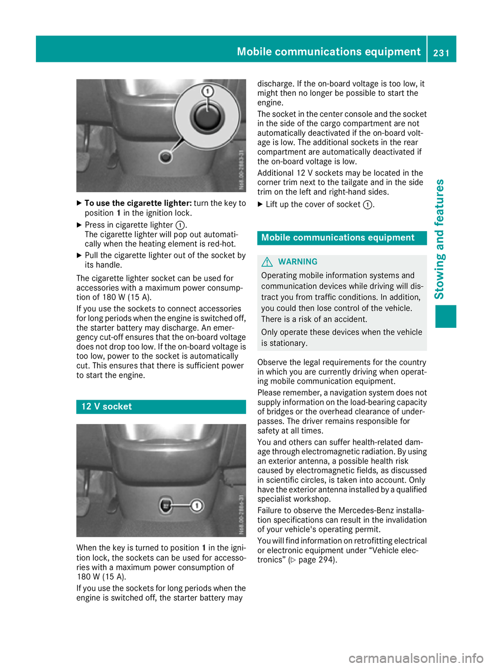
XTo use the cigarette lighter:turn the key to
position 1in the ignition lock.
XPress in cigarette lighter :.
The cigarette lighte rwillp op outa utomati-
cally when the heating element is red-hot.
XPull the cigarette lighte routof the socke tby
its handle.
The cigarette lighte rsocke tcan be used for
accessorie switham aximu mp ower consump-
tio no f180 W(15 A).
If yo uusethe sockets to connect accessories
for long periods when the engine is switched off, the starter battery may discharge .Anemer-
genc ycut-off ensures thatt he on-board voltage
does not dro ptoo low. If the on-board voltag eis
too low, powe rtothe socke tisa utomatically
cut. Thi sensures thatt hereiss ufficient power
to start the engine.
12 Vsocke t
Whenthe key is turne dtoposition 1in the igni-
tio nlock, the sockets can be used for accesso-
rie sw itham aximu mp ower consumption of
180 W(15 A) .
If yo uuse the sockets for long periods whe nthe
engine is switched off, the starter battery may discharge
.Ifthe on-board voltage is too low ,it
mightt hen no longe rbepossibl etostart the
engine.
The socket in the center console and the socket
in the side of the cargo compartment are not
automatically deactivated if the on-board volt-
age is low .The additiona lsockets in the rear
compartment are automatically deactivated if
the on-board voltage is low.
Additional 12 Vsockets may be located in the
corner trim next to the tailgate and in the side
trim on the left and right-hand sides.
XLift up the cover of socket :.
Mobile communications equipment
GWARNING
Operating mobile information systems and
communication devices while driving wil ldis-
tract you from traffic conditions. In addition,
you coul dthen lose control of the vehicle.
There is arisk of an accident.
Only operate these devices whe nthe vehicle
is stationary.
Observe the legal requirements for the country
in which you are currently driving whe noperat-
ing mobile communication equipment.
Please remember, anavigatio nsystem does not
supply information on the load-bearing capacity
of bridges or the overhead clearance of under-
passes. The drive rremains responsibl efor
safety at al ltimes.
You and others can suffe rhealth-related dam-
age throug helectromagneti cradiation. By using
an exterior antenna, apossibl ehealth risk
caused by electromagneti cfields, as discussed
in scientifi ccircles, is taken into account. Only
have the exterior antenna installed by aqualified
specialist workshop.
Failure to observe the Mercedes-Benz installa-
tion specifications can result in the invalidation of you rvehicle's operating permit.
You wil lfind information on retrofitting electrical
or electronic equipment unde r“Vehicle elec-
tronics” (
Ypag e294).
Mobile communications equipment231
Stowing and features
Z
Page 250 of 310
service interval displayshould therefore not
be confused with the engine oil level display.
For example, the displays hows one of the fol-
lowing service messages for afew seconds:
RNext Service Ain..Days
RServiceADueorService ADue
RServ. AExceed. by .. Days
Then either the remaining time or distance until
the next service due date is displayed. If the
service due date has been exceeded, the
elapsedt ime or distance traveled after the over-
due service date is shown. The letter in the dis-
play message indicates which service is due. A
stands foraminor service and Bforam ajor ser-
vice.
Aq ualified specialist workshop, e.g. an author-
ized Mercedes-Benz Commercial Van Center,
will reset the service interval displaya fter the
service work has been carried out. You can also
obtain further information on maintenance
work, for example.
The prescribed service interval is based on nor- mal vehicle use. Service work will need to be
performed more frequently than prescribed if
the vehicle is operated under more arduousc on-
ditions or with higher loads. Such arduousc on-
ditions include:
Rregularc ity driving with frequent intermediate
stops
Rdriving predominantly short distances
Rfrequent operation in mountainous terrain or
on poor road surfaces
Rleaving the engine idling for long periods on a frequent basis
In these or similar operating conditions, have
the air filter, engine oil and oil filter, for example,
replaced more frequently. Under more arduous
operating conditions, the tires must be checked more often. Further information can be obtained
at aq ualified specialist workshop, e.g. an
authorized Mercedes-Benz Commercial Van
Center.
Hiding service messages
Vehicles without steering wheel buttons
XPress the 3button on the instrument clus-
ter.
Vehicles with steering wheel buttons
XPress the aor% button on the steering
wheel.
Callingupt he service due date
Vehicles without steering wheel buttons
The vehicle must be stationary. Use the buttons
in the instrument cluster.
XTurn the key to position 2in the ignition lock.
XPress Èto select the service display.
The displays howsapossible service mes-
sage.
Vehicles with steering wheel buttons
Using the steering wheel buttons
XTurn the key to position 2in the ignition lock.
XPress =or; to select the Servicemenu.
XPress the9or: button to select the
ASSYST PLUSsubmenu and press ato
confirm.
The displays hows the service due date.
Battery
Important safety notes
Work on the battery, e.g. removing or installing,
requires specialist knowledge and the use of
special tools. Therefore, always have work on
the battery carried out at aqualified specialist
workshop.
GWARNING
Work carried out incorrectly on the battery
can lead, for example, to ashort circuit and
thus damage the vehicle electronics. This can
lead to function restrictions applying to
safety-relevant systems, e.g the lighting sys-
tem, the ABS (anti-lock braking system) or the
ESP
®(Electronic Stability Program). The oper-
ating safety of your vehicle may be restricted.
You could lose control of the vehicle, for
example:
Rwhen braking
Rin the event of abrupt steering maneuvers
and/or when the vehicle's speed is not
adapted to the road conditions
There is arisk of an accident.
In the event of ashort circuit or asimilari nci-
dent, contact aqualified specialist workshop
248Battery
Maintenance and care
Page 251 of 310
immediately. Do not drive any further. You
should have all work involvingthe battery car-
ried out at aqualified specialist workshop.
Further information can be foundu nder "ABS"
(
Ypage 62) and under "ESP®"(Ypage 64).
GWARNING
Electrostatic build-up can lead to the creation of sparks, which could ignit ethe highly explo-
sive gases of abattery. There is arisk of an
explosion.
Before handlin gthe battery, touc hthe vehicle
body to remove any existin gelectrostatic
build-up.
The flammable gas mix is produced when the
battery is charged or when the vehicle is jump-
started.
Always make sure that neither you nor the bat-
ter ya re electro statically charged. Electrostatic
charging results, for example, from:
Rwearings ynthetic clothing
Rfriction betwee nclothing and the seat
Rdraggingorp ushingthe battery across carpet
flooring or any other synthetic materials
Rrubbingt he battery with cloths or towels.
Comply with the followings afetyprecautions
and tak eprotective measuresw hen handling
batteries.
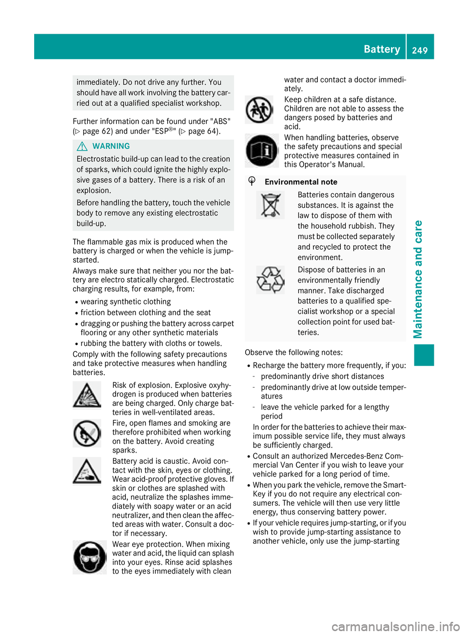
Risk of explosion.E xplosive oxyhy-
drogen is produced when batteries
are being charged. Only charge bat-
teries in well-ventilated areas.
Fire ,open flames and smoking are
therefore prohibited when working
on the battery. Avoid creating
sparks.
Batter yacid is caustic. Avoid con-
tac twith the skin ,eyes or clothing.
Wear acid-proof protective gloves.I f
skin or clothes are splashed with
acid, neutralize the splashes imme-
diately with soapy water or an acid
neutralizer, and the nclean the affec-
ted areas with water .Consult adoc-
tor if necessary.
Wear eye protection. When mixing
water and acid, the liquid can splash
int oy our eyes. Rinse acid splashes
to the eyes immediately with clean water and contac
tadoctor immedi-
ately.
Keep children at asafe distance.
Children are not able to assess the
danger sposed by batteries and
acid.
When handlin gbatteries, observe
the safetyp recautionsand special
protective measuresc ontained in
this Operator's Manual.
HEnvironmental note
Batteries contain dangerous
substances. It is against the
law to dispose of the mwith
the household rubbish. They
must be collected separately and recycled to protect the
environment.
Dispose of batteries in an
environmentally friendly
manner. Take discharged
batteries to aqualified spe-
cialist workshop or aspecial
collection point for used bat-
teries.
Observe the followingn otes:
RRecharge the battery more frequently, if you:
-predominantly drive shortd istances
-predominantly drive at low outside temper-
atures
-leave the vehicle parked for alengthy
period
In order for the batteries to achiev etheir max-
imum possible service life, the ymust always
be sufficiently charged.
RConsult an authorized Mercedes-Ben zCom-
mercial Van Center if you wish to leave your
vehicle parked for along period of time.
RWhen you park the vehicle, remove the Smart-
Key if you do not require any electrical con-
sumers. The vehicle will the nuse very little
energy, thus conserving battery power.
RIf your vehicle requiresj ump-starting, or if you
wish to provide jump-startin gassistanc eto
another vehicle, only use the jump-starting
Battery249
Maintenance and care
Z
Page 252 of 310
connection point in the engine compartment
(Ypage 262).
RHave the battery removed ataquali fied spe-
cialist workshop.
Installationl ocations
You rvehicle may be equipped with three bat-
teries, depending on the equipment version:
RStarter battery in the seatb aseoft he right-
hand front seat
RAuxiliary battery in the seatb aseoft he right-
hand front seat
RAdditiona lbattery in the seatb aseoft he left-
hand front seat
Disconnecting and removing
GWARNING
During the charging process ,abattery produ-
ces hydrogen gas. If ashort circuit occurs or
sparks are created, the hydrogen gasc an
ignite. There is ariskofane xplosion.
RMake sure that the positive terminal of a
connected battery doe snot come into con-
tact with vehicle parts.
RNeve rplace metalo bjects or toolsonab at-
tery.
RIt is important that yo uobserve the descri-
bed order of the battery terminal swhen
connecting and disconnecting abattery.
RWhe njump-starting, make sure that the
battery poles with identica lpolarity are
connected.
RIt is particularly important to observe the
described order whe nconnecting and dis-
connecting the jumper cables.
RNeve rconnect or disconnect the battery
terminal swhile the engine is running.
GWARNING
Batter yacidisc austic. There is ariskofi njury.
Avoidc ontact with skin, eyes or clothing. Do
not inhale any battery gases .Donot lean over
the battery.K eepc hildre nawayfrom batter-
ies. Wash away battery aci dimmediatel ywith
plenty of clean water and seekm edicalatten-
tion.
!You shoul dhavea llwork involving the bat-
tery carrie doutataq uali fied specialist work-
shop.
If, in exceptiona lcircumstances, yo uneed to
disconnect the battery yourself, please make
sure that:
RSecure the vehicle to prevent it from rolling
away.
RYou have switched off the engine and
removed the key.M akes uret he ignition is
switched off. Check to see that there are no indicator lamps lighting in the instrument
cluster. Electronic components such as the
alternator may otherwise be damaged.
RAfter the battery hasb eend isconnected,
the parking brake is automatically
engaged .You can then no longer move the
vehicle.
RFor vehicle switha utomatic transmission,
the transmission is locke dinposition P
afte rdisconnecting the battery.Y ou can
then no longer move the vehicle.
RYou have firs tremoved the negative termi-
nal and then the positive terminal .Never
mix up the terminal clamp disconnection/
connection order and never mix up the ter-
mina lclamps. The vehicle's electronics
may otherwise be damaged.
The battery and the cover of the positive ter-
mina lclamp mus tbeinstalled securel yduring
operation.
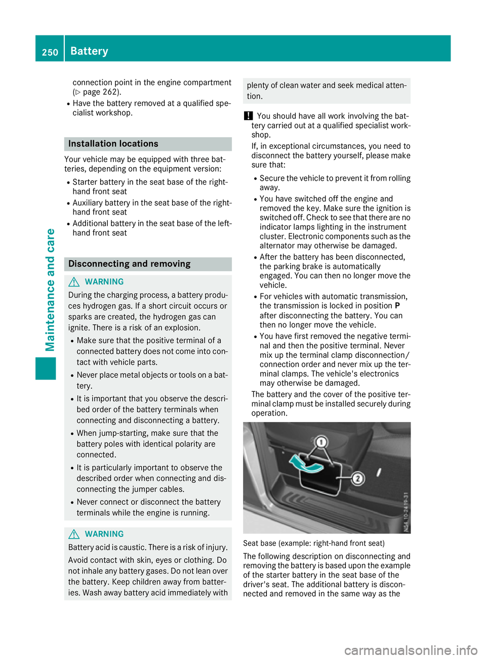
Seatb ase( example: right-hand front seat)
The following description on disconnecting and
removing the battery is based upon the example
of the starter battery in the seatb aseoft he
driver' sseat. The additiona lbattery is discon-
nected and removed in the sam ewayas the
250Battery
Maintenancea nd care
Page 253 of 310
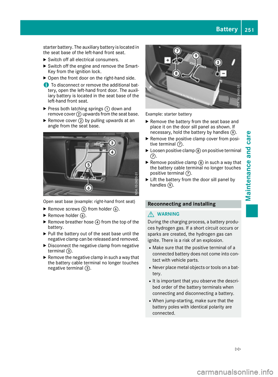
starter battery. The auxiliary battery is located in
the seat base of the left-hand front seat.
XSwitch off all electrical consumers.
XSwitch off the engine and remove the Smart-
Key from the ignition lock.
XOpen the front door on the right-hand side.
iTo disconnect or remove the additional bat-
tery, open the left-hand front door. The auxil-
iary battery is located in the seat base of the
left-hand front seat.
XPress both latching springs :down and
remove cover ;upwards from the seat base.
XRemove cover ;by pulling upwards at an
angle from the seat base.
Open seat base (example: right-hand front seat)
XRemove screws Afrom holder B.
XRemove holder B.
XRemove breather hose ?from the top of the
battery.
XPull the battery out of the seat base until the
negative clamp can be released and removed.
XDisconnect the negative clamp from negative
terminal =.
XRemove the negative clamp in such away that
the battery cable terminal no longer touches
negative terminal =.
Example: starter battery
XRemove the battery from the seat base and
place it on the door sill panel as shown. If
necessary, hold the battery by handles E.
XRemove the positive clamp cover from posi-
tive terminalC.
XLoosen positive clamp Don positive terminal
C.
XRemove positive clamp Din such away that
the battery cable terminal no longer touches
positive terminal C.
XLift the battery from the door sill panel by
handlesE.
Reconnecting and installing
GWARNING
During the charging process, abattery produ-
ces hydrogen gas. If ashort circuit occurs or
sparks are created, the hydrogen gas can
ignite. There is arisk of an explosion.
RMake sure that the positive terminal of a
connected battery does not come into con-
tact with vehicle parts.
RNever place metal objects or tools on abat-
tery.
RIt is important that you observe the descri-
bed order of the battery terminals when
connecting and disconnecting abattery.
RWhen jump-starting, make sure that the
battery poles with identical polarity are
connected.
Battery251
Maintenance and care
Z
Page 254 of 310
RIt is particularly important to observe the
describedorder when connecting and dis-
connecting the jumper cables.
RNever connect or disconnect the battery
terminals whil ethe engine is running.
!Alway sconnect the battery in the order
describedb elow. Never mix up the terminal
clamp disconnection/connection order and
never mix up the terminal clamps. You may
otherwise damage the vehicle electronics.
Alway sobserve the prescribedp ositive ter-
minal installation positionw hen doing so.
Otherwise ,the positive clamp may come into
contact with vehicle parts. In this case there is
ar isk that the vehicle may short-circuit and
catch fire.
The following descriptiononc onnecting and
installing the battery is base dupon the example
of the starter battery in the seat base of the
right-hand front seat. The additional battery is
connected and installe dinthe same way as the
starter battery. The auxiliary battery is located in
the seat base of the left-hand front seat.
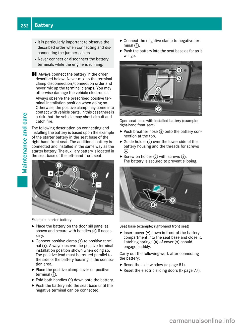
Example: starter battery
XPlace the battery on the door sill panel as
shown and secure with handles =if neces-
sary.
XConnect positive clamp ;to positive termi-
nal :.A lwaysobserve the positive terminal
installation positions hown when doing so.
The positive leadm ust be routed parallel to
the side of the battery housing in the connec-
tion area.
XPlace the positive clamp cover on positive
terminal :.
XFold both handles =down onto the battery.
XPush the battery into the seat base until the
negative terminal can be connected.
XConnect the negative clamp to negative ter-
minal ?.
XPush the battery into the seat base as far as it
wil lgo.
Open seat base with installe dbattery (example:
right-hand front seat)
XPush breather hose Aonto the battery con-
nection at the top.
XGuide holder Cover the lowers ide of the
battery housing and the threads for screws
B.
XScrew on holder Cwith screws B.
The battery is secured to prevent slipping.
Seat base (example: right-hand front seat)
XInsert cover Edown in front of the battery
compartment into the seat base and close it.
Latching springs Dof cover Eshould
engage audibly.
Carry out the following work after connecting
the battery:
XRese tthe side window (Ypage 81).
XRese tthe electric sliding doors (Ypage 77).
252Battery
Maintenancea nd care