tires MERCEDES-BENZ METRIS 2017 MY17 Operator’s Manual
[x] Cancel search | Manufacturer: MERCEDES-BENZ, Model Year: 2017, Model line: METRIS, Model: MERCEDES-BENZ METRIS 2017Pages: 318, PDF Size: 5.01 MB
Page 303 of 318
Spare wheel
Important safety notes
GWARNING
Wheel and tire dimensions as well as the type of tire can vary between the spare wheel and
the wheel to be replaced. When the spare
wheel is mounted, driving characteristics may be severely affected. There is a risk of an acci-
dent.
In order to reduce risks:
Ryou should therefore adapt your driving
style and drive carefully.
Rnever mount more than one spare wheel
that differs from the wheel to be replaced.
Ronly use a spare wheel that differs from the
wheel to be replaced for a short time.
Rdo not deactivate ESP®.
Rhave a spare wheel that differs from the
wheel that has been changed replaced at
the nearest qualified specialist workshop.
You must observe the correct wheel and
tire dimensions as well as the wheel type.
When using a spare wheel of a different size, do
not exceed the maximum permissible speed of
50 mph (80 km/h).
General notes
The procedure for mounting the spare wheel is
described in "Mounting a wheel" (Ypage 297).
The following should be checked regularly, par-
ticularly prior to long journeys:
Rthe tire pressure of the spare wheel, which
should then be corrected if necessary
(
Ypage 280)
Rthe fastenings of the spare wheel bracket
The spare wheel is located either in the left rear
compartment or in a spare wheel bracket under
the vehicle.
Replace the tires after six years at the latest,
regardless of wear. This also applies to the spare
wheel.
Vehicles with tire pressure monitor: the
spare wheel is not equipped with a sensor for
monitoring tire pressure. If you have installed a spare wheel, the tire pressure monitor will not
function for this wheel. The system may con-
tinue to show the tire pressure of the wheel that
has been removed for a few minutes. The value
displayed for the position where the spare wheel
is installed is not the same as the current tire
pressure of the spare wheel.
When you are driving with the spare wheel
mounted, the tire pressure monitor cannot func-
tion reliably. Only restart the tire pressure mon- itor when the defective wheel has been replaced
with a new wheel and sensor.
More Information can be found under "Tire pres-
sure monitor" (
Ypage 284).
Removing and installing the spare
wheel
Spare wheel under the rear of the vehi-
cle
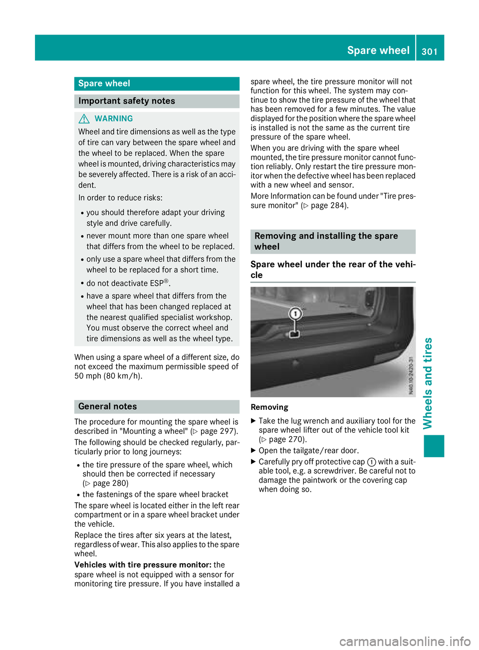
Removing
XTake the lug wrench and auxiliary tool for the
spare wheel lifter out of the vehicle tool kit
(
Ypage 270).
XOpen the tailgate/rear door.
XCarefully pry off protective cap :with a suit-
able tool, e.g. a screwdriver. Be careful not to
damage the paintwork or the covering cap
when doing so.
Spare wheel301
Wheels and tires
Z
Page 304 of 318
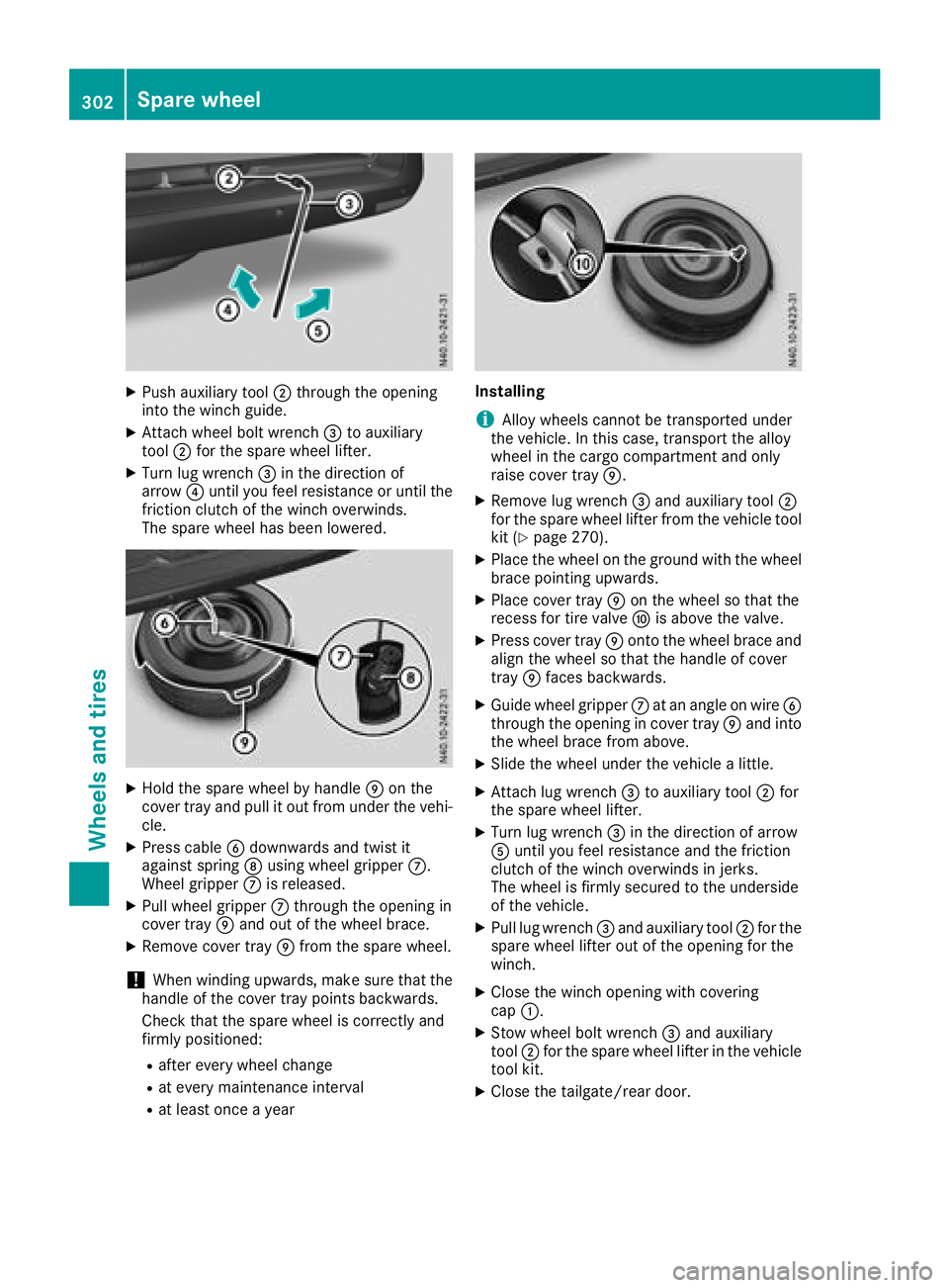
XPush auxiliary tool;through the opening
into the winch guide.
XAttach wheel bolt wrench =to auxiliary
tool ;for the spare wheel lifter.
XTurn lug wrench =in the direction of
arrow ?until you feel resistance or until the
friction clutch of the winch overwinds.
The spare wheel has been lowered.
XHold the spare wheel by handle Eon the
cover tray and pull it out from under the vehi-
cle.
XPress cable Bdownwards and twist it
against spring Dusing wheel gripper C.
Wheel gripper Cis released.
XPull wheel gripper Cthrough the opening in
cover tray Eand out of the wheel brace.
XRemove cover tray Efrom the spare wheel.
!When winding upwards, make sure that the
handle of the cover tray points backwards.
Check that the spare wheel is correctly and
firmly positioned:
Rafter every wheel change
Rat every maintenance interval
Rat least once a year
Installing
iAlloy wheels cannot be transported under
the vehicle. In this case, transport the alloy
wheel in the cargo compartment and only
raise cover tray E.
XRemove lug wrench =and auxiliary tool ;
for the spare wheel lifter from the vehicle tool
kit (
Ypage 270).
XPlace the wheel on the ground with the wheel brace pointing upwards.
XPlace cover tray Eon the wheel so that the
recess for tire valve Fis above the valve.
XPress cover tray Eonto the wheel brace and
align the wheel so that the handle of cover
tray Efaces backwards.
XGuide wheel gripper Cat an angle on wire B
through the opening in cover tray Eand into
the wheel brace from above.
XSlide the wheel under the vehicle a little.
XAttach lug wrench =to auxiliary tool ;for
the spare wheel lifter.
XTurn lug wrench =in the direction of arrow
A until you feel resistance and the friction
clutch of the winch overwinds in jerks.
The wheel is firmly secured to the underside
of the vehicle.
XPull lug wrench =and auxiliary tool ;for the
spare wheel lifter out of the opening for the
winch.
XClose the winch opening with covering
cap :.
XStow wheel bolt wrench =and auxiliary
tool ;for the spare wheel lifter in the vehicle
tool kit.
XClose the tailgate/rear door.
302Spare wheel
Wheels and tires
Page 314 of 318
The dimensions specified vary according to:
RTires
RLoad
RCondition of the suspension
ROptional equipment
ModelCargo Van
Opening height of the
tailgate:86.0 in (2185 mm)
Opening range of the
tailgate;41.2 in (1047 mm)
Opening range of the
rear doors =33.4 in (849 mm)
Load width50.0 in (1270 mm)
Max. load width66.3 in (1685 mm)
Load height53.8 in (1367 mm)
Vehicle length202.4 in
(5140 mm)
Vehicle width
Including exterior mir-
rors
Excluding exterior mir-
rors
88.3 in (2244 mm)
75.9 in (1928 mm)
Wheelbase126.0 in
(3200 mm)
ModelPassenger Vans
Opening height of the
tailgate :84.6 in (2150 mm)
Opening range of the
tailgate;41.2 in (1047 mm)
Opening range of the
rear doors =33.4 in (849 mm)
Load width47.4 in (1205 mm)
Max. load width61.1 in (1552 mm)
Load height52.2 in (1326 mm)
Vehicle length202.4 in
(5140 mm)
ModelPassenger Vans
Vehicle width
Including exterior mir-
rors
Excluding exterior mir-
rors
88.3 in (2244 mm)
75.9 in (1928 mm)
Wheelbase126.0 in
(3200 mm)
Cargo tie-down points and carrier sys-
tems
Cargo tie-down points
General notes
!Observe the information on the maximum
loading capacity of the individual cargo tie-
down points.
If you use several cargo tie-down points to
secure a load, you must always take the max-
imum loading capacity of the weakest cargo
tie-down point into account.
If you brake hard, for example, the forces act-
ing could be up to several times the weight
force of the load. Always use multiple cargo
tie-down points in order to distribute the force absorption. Load the anchorages evenly.
You will find additional information about cargo
tie-down points and cargo tie-down rings in the
"Securing loads" section (
Ypage 244).
Cargo tie-down rings
The maximum tensile load of the cargo tie-down
rings is:
Cargo tie-down
ringsPermissible nomi- nal tensile load
Passenger Vans786.5 lbf
(350 daN)
Cargo Van1124.0 lbf (500 daN)
312Vehicle data
Technical data