oil MERCEDES-BENZ METRIS 2018 MY18 Operator’s Manual
[x] Cancel search | Manufacturer: MERCEDES-BENZ, Model Year: 2018, Model line: METRIS, Model: MERCEDES-BENZ METRIS 2018Pages: 318, PDF Size: 5.07 MB
Page 257 of 318
XOpen the hood (Ypage 253).
XPull out oil dipstick:.
XWipe oil dipstick:using a lint-free cloth.
XInsert oil dipstick :back into the guide tube
as far as it will go and remove it again.
If the level is between MIN mark =and MAX
mark ;, the oil level is adequate.
XIf the oil level has dropped to or below mini-
mum mark =, open cap ?and add engine oil
(
Ypage 255).
The difference in quantity between marks ;
and =is approximately 2 US quarts (2 liters).
XClose the hood.
Add engine oil
GWARNING
Opening the hood when the engine is over-
heated or when there is a fire in the engine
compartment could expose you to hot gases
or other service products. There is a risk of
injury.
Let an overheated engine cool down before
opening the hood. If there is a fire in the
engine compartment, keep the hood closed
and contact the fire department.
GWARNING
Certain components in the engine compart-
ment, such as the engine, radiator and parts
of the exhaust system, can become very hot.
Working in the engine compartment poses a
risk of injury.
Where possible, let the engine cool down and touch only the components described in the
following.
GWARNING
If engine oil comes into contact with hot com- ponents in the engine compartment, it may
ignite. There is a risk of fire and injury.
Make sure that engine oil is not spilled next to
the filler neck. Let the engine cool down and
thoroughly clean the engine oil off the com-
ponents before starting the engine.
HEnvironmental note
When adding oil, take care not to spill any. If
oil enters the soil or waterways, it is harmful to
the environment.
!Do not add too much oil. adding too much
engine oil can result in damage to the engine
or to the catalytic converter. Have excess
engine oil siphoned off.
!Do not use any additives in the engine oil.
This could damage the engine.
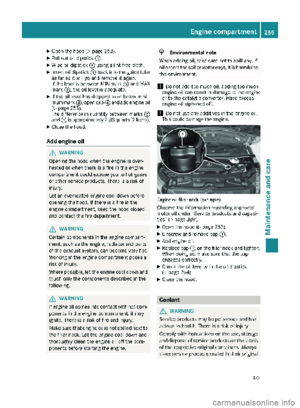
Engine oil filler neck (example)
Observe the information regarding approved
motor oil under "Service products and capaci-
ties" (
Ypage 309).
XOpen the hood (Ypage 253).
XUnscrew and remove cap :.
XAdd engine oil.
XReplace cap:on the filler neck and tighten.
When doing so, make sure that the cap
engages correctly.
XCheck the oil level with the oil dipstick
(Ypage 254).
XClose the hood.
Coolant
GWARNING
Service products may be poisonous and haz-
ardous to health. There is a risk of injury.
Comply with instructions on the use, storage
and disposal of service products on the labels
of the respective original containers. Always
store service products sealed in their original
Engine compartment255
Maintenance and care
Z
Page 259 of 318
Adding coolant
XIfthe coolant drops under marker bar=in
the filler neck, add coolant.
Observe the information on the correct cool-
ant mixture rat ioand the required water qual-
ity under "Service products and capacities"
(
Ypage 311). To prevent damage to the
engine co oling system, use only appr oved
corrosion inh ibitor/antifreeze that co mplies
wit h the Mercedes-Benz Specifications for
Service Products.
XReplac e cap:and tighten ina clock wise
dire ction.
XStart the engine.
XSet the temperature inthe veh icleinterior to
the maximum output on the air-conditioning
system control panel.
XAfter approximate lyfive minutes, switch off
the engine again and allow itto cool down.
XCheck the coolant level again and add coolant
ifnecessary.
XClose the hood.
Brake fluid
GWAR NING
Service products may be poisonous and haz-
ardous to health. There isa risk of injury.
Comp ly with instructions on the use, storage
and dispo sal of service products on the labels
of the respective original containers. Always
store service products sealed intheir original
containers. Always keep service products out
of the reach of ch ildren.
GWAR NING
Opening the hood when the engine isover-
heated or when there isa fire inthe engine
compartment could expose you to hot gases
or other service products. There isa risk of
injury.
Let an overheated engine cool downbefore
opening the hood. Ifthere isa fire inthe
engine compartment, keep the hood closed
and contact the fire department.
GWARNING
Certain components in the engine compart-
ment, such as the engine, radiator and parts
of the exhaust system, can become very hot.
Working in the engine compartment poses a
risk of injury.
Where possible, let the engine cool downand
touch only the components describe d in the
foll owin g.
Brake fluid is hazardous to health. Also observe the safety notes under "Service products and
capacities" (
Ypage 306).
GWARNING
The brake fluid constantly absorbs moisture
from the air. This lowers the boiling point of
the brake fluid. Ifthe boilin g point of the brake
fluid is too low,vapor pockets may form in the
brake system when the brakes are applied
hard. This would impair braking efficiency.
There is a risk of an accident.
You should have the brake fluid renewed at
the specified intervals.
!If the brake fluid level in the brake fluid res-
ervoir has fallen to the MIN mark or below,
check the brake system immediately for
leaks. Also check the thickness of the brake
linings. Visit a qualified specialist workshop
immediately.
Do not add brake fluid. This does not correct
the malfunction.
!Brake fluid corrodes paint, plastic and rub-
ber. Ifpaint, plastic or rubber has come into
contact with brake fluid, rinse with water
immediately.
Have the brake fluid renewed every two years at a qualified specialist workshop. Observe the
information regarding brake fluid in the "Service
products and capacities" section (
Ypage 311).
Engine compartment257
Maintenance and care
Z
Page 261 of 318
Maintenance
General notes
HEnvironmental note
Observe measures to protect the environ-
ment when working on the vehicle. You must
observe the legal requirements when dispos-
ing of service products, e.g. engine oil. This
also includes all components, e.g. filters,
which have come into contact with service
products. Any qualified specialist workshop
can provide information about this.
Dispose of empty containers, cleaning cloths
and care products in an environmentally
responsible manner. Comply with the instruc-
tions for use of the care products.
Do not run the engine for longer than neces-
sary when the vehicle is stationary.
Before carrying out maintenance measures and
repairs, you must read the following documents
relating to maintenance measures and repairs:
Rrelevant sections of the technical documen-
tation such as the Operator's Manual and
workshop information
Rlegal stipulations such as work safety regula-
tions and accident prevention regulations
While working under the vehicle, you must
secure the vehicle on jack stands with sufficient load capacity.
Never use a vehicle jack instead of stands. The
jack is designed only to raise the vehicle for a
short time when changing a wheel. It is not
suited for performing maintenance work under
the vehicle.
Please also refer to the notes about qualified
specialist workshops (
Ypage 31).
The scope and regularity of the inspection and
maintenance work primarily depend on the
often diverse operating conditions. Specialist
knowledge beyond the scope of this Operator's
Manual is required when carrying out testing
and maintenance work. This work should only be
carried out by trained staff.
The vehicle Maintenance Booklet describes the scope and frequency of maintenance work and
contains additional notes on the Limited War-
ranty. You will find information about service
products approved by Mercede s-Benz a
ndcapacities under "Service products and capaci-
ties" (
Ypage 306)
Maintenance services must be carried out in
accordance with the provisions and recommen- dations in the Maintenance Booklet. Not doing
so could void the warranty claim and lead to
refusal of goodwill gestures after the manufac-
turer has submitted a damage report.
Observe the information under "Mercedes-Benz
genuine parts" (
Ypage 33).
Service interval display
General notes
The service interval display informs you of the
next service due date. Information on the type of
service and service intervals can be found in the
Maintenance Booklet.
iThe service interval display does not provide
information about the engine oil level. The
service interval display should therefore not
be confused with the engine oil level display.
For example, the display shows one of the fol-
lowing service messages for a few seconds:
RService A in .. days
RService A Dueor Service A Due
RServ. A Exceed. by .. Days
Then either the remaining time or distance until
the next service due date is displayed. If the
service due date has been exceeded, the
elapsed time or distance traveled after the over-
due service date is shown. The letter in the dis-
play message indicates which service is due. A
stands for a minor service andBfor a major ser-
vice.
A qualified specialist workshop, e.g. an author-
ized Mercedes-Benz Commercial Van Center,
will reset the service interval display after the
service work has been carried out. You can also
obtain further information on maintenance
work, for example.
The prescribed service interval is based on nor- mal vehicle use. Service work will need to be
performed more frequently than prescribed if
the vehicle is operated under more arduous con-
ditions or with higher loads. Such arduous con-
ditions include:
Rregular city driving with frequent intermediate
stops
Rdriving predominantly short distances
Maintenance259
Maintenance and care
Z
Page 262 of 318
Rfrequent operation in mountainous terrain or
on poor road surfaces
Rleaving the engine idling for long periods on a
frequent basis
In these or similar operating conditions, have
the air filter, engine oil and oil filter, for example,
replaced more frequently. Under more arduous
operating conditions, the tires must be checked more often. Further information can be obtained
at a qualified specialist workshop, e.g. an
authorized Mercedes-Benz Commercial Van
Center.
Hiding service messages
Vehicles without steering wheel buttons
XPress the 3button on the instrument clus-
ter.
Vehicles with steering wheel buttons
XPress the aor% button on the steering
wheel.
Calling up the service due date
Vehicles without steering wheel buttons
The vehicle must be stationary. Use the buttons
in the instrument cluster.
XTurn the SmartKey to position 2in the ignition
lock.
XPress Èto select the service display.
The display shows a possible service mes-
sage.
Vehicles with steering wheel buttons
Using the steering wheel buttons
XTurn the SmartKey to position 2in the ignition
lock.
XPress =or; to select the Servicemenu.
XPress9or: to select the ASSYSTPLUSsubmenu and press ato confirm.
The display shows the service due date.
Battery
Important safety notes
Work on the battery, e.g. removing or installing,
requires specialist knowledge and the use of
special tools. Therefore, always have work on the battery carried out at a qualified specialist
workshop.
GWARNING
Work carried out incorrectly on the battery
can lead, for example, to a short circuit and
thus damage the vehicle electronics. This can
lead to function restrictions applying to
safety-relevant systems, e.g. the lighting sys-
tem, the ABS (anti-lock braking system) or the
ESP
®(Electronic Stability Program). The oper-
ating safety of your vehicle may be restricted.
You could lose control of the vehicle, for
example:
Rwhen braking
Rin the event of abrupt steering maneuvers
and/or when the vehicle's speed is not
adapted to the road conditions
There is a risk of an accident.
In the event of a short circuit or a similar inci-
dent, contact a qualified specialist workshop
immediately. Do not drive any further. You
should have all work involving the battery car- ried out at a qualified specialist workshop.
Further information can be found under "ABS"
(
Ypage 64) and under "ESP®" (Ypage 65).
GWARNING
Electrostatic build-up can lead to the creation of sparks, which could ignite the highly explo-
sive gases of a battery. There is a risk of an
explosion.
Before handling the battery, touch the vehicle
body to remove any existing electrostatic
build-up.
The flammable gas mix is produced when the
battery is charged or when the vehicle is jump-
started.
Always make sure that neither you nor the bat-
tery are electro statically charged. Electrostatic
charging results, for example, from:
Rwearing synthetic clothing
Rfriction between clothing and the seat
Rdragging or pushing the battery across carpet
flooring or any other synthetic materials
Rrubbing the battery with cloths or towels.
260Battery
Maintenance and care
Page 269 of 318
and associated spray produced by the power
washer could cause extensive damage to thevehicle.
!When using high-pressure cleaning equip-
ment, maintain a minimum distance of
approx. 1 ft (30 cm)betwee nthe spra ynozzle
and th evehicl eparts. Do no tuse apowe r
washer wit h around-jet nozzle. You could
damage th evehicl eor engin eparts.
!Kee pth ewater je tmovin gconstantl ywhile
cleaning .This will avoid causin gdamage to
th evehicle.
Do no tpoin tth ewater je tat:
Rdoo rjoints
Rrear vie wcamera
Rair bellows
Rbrak ehoses
Rwhee lbalance weights
Relectrica lcomponent s
Relectricalconnection s
Rseals
Rdrive train ,especially no tat th eintermedi-
ate bearin gof th epropelle rshaf t
Cleaning the engine
!Water mus tno tente rintak eor ventilation
openings. Whe ncleaning wit hhigh pressur e
water or steam cleaners ,th espray mus tno t
be aime ddirectl yat electrica lcomponent sor
th eterminals of electrica llines.
Preserve th eengin eafter th eengin ehas been
cleaned. Protect th ebelt drive system from
exposure to th epreservative agent.
Also observ eth einformation under "Powe r
washers " (
Ypage 266).
Cleaning the paintwork
!Do notaffix:
Rstickers
Rfilm s
Rmagneti cplates or similar items
to painte dsurfaces. You could otherwise
damage th epaintwork .
Scratches, corrosiv edeposits, area saffecte dby
corrosio nand damage caused by inadequate
car ecanno talways be completely repaired. In
suc hcases, visit aqualified specialist workshop .
XRemove impurities immediately, wher epos -
sible, whils tavoidin grubbin gto ohard.
XSoak insec tremain swit hinsec tremove rand
rinse off th etreated area safterwards .
XSoak birddroppings wit hwater and rinse off
th etreated area safterwards .
XRemove coolant, brak efluid, tree resin ,oils ,
fuel sand greases by rubbin ggentl ywit h a
cloth soaked in petroleum ether or lighte r
fluid.
XUse tar remove rto remove tar stains.
XUse silicon eremove rto remove wax .
Cleaning the windows
GWARNING
You could become trapped by th ewindshield
wiper sif they start movin gwhile cleaning th e
windshield or wiper blades. There is aris kof
injury.
Always switch off th ewindshield wiper sand
th eignition before cleaning th ewindshield or
wiper blades.
!Do no tfol dth ewindshield wiper saway from
th ewindshield unless th ehoo dis closed .Oth-
erwise, you could damage th ehood.
!Hold th ewiper arm securel ywhen foldin g
back. The windshield could be damaged if th e
wiper arm smack sagainst it suddenly.
!Do no tuse dry cloths, abrasiv eproducts ,
solvents or cleaning agents containin gsol-
vents to clean th einside of th ewindows .Do
no ttouch th einside sof th ewindows wit h
har dobjects ,e.g. an ice scrape ror ring. There
is otherwise aris kof damagin gth ewindows .
!Clean thewater drainag echannels of th e
windshield and th erear window at regular
intervals. Deposit ssuc has leaves, petals and
pollen may under certain circumstances pre -
ven twater from draining away. This can lead
to corrosio ndamage and damage to elec -
tronic components.
XClean th einside and outside of th ewindows
wit h a damp cloth and acleaning agen tthat is
recommended and approve dby Mercedes -
Benz .
Care267
Maintenance and care
Z
Page 271 of 318
Cleaning the rear view camera
!Do not use dry, coarse or hard cloths and do
not scrub. You could otherwise scratch or
damage the lens of the rear view camera.
When cleaning the vehicle with a high-pres-
sure or steam cleaner, observe a minimum
distance of 1.6 ft (50 cm) to the rear view
camera. Do not aim directly at the rear view
camera. You could otherwise damage the rear
view camera.
Make sure that you do not apply any wax to
camera lens when waxing the vehicle. If neces-
sary, remove the wax using water, shampoo and a soft cloth.
Vehicles with rear doors
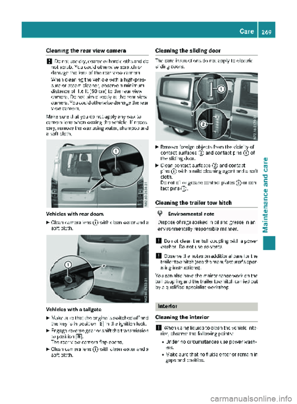
XClean camera lens :with clean water and a
soft cloth.
Vehicles with a tailgate
XMake sure that the engine is switched off and
the key is in position 2in the ignition lock.
XEngage reverse gear or shift the transmission
to position k.
The rear view camera flap opens.
XClean camera lens :with clean water and a
soft cloth.
Cleaning the sliding door
The care instructions do not apply to electric
sliding doors.
XRemove foreign objects from the vicinity of
contact surfaces ;and contact pins :of
the sliding door.
XClean contact surfaces ;and contact
pins :with a mild cleaning agent and a soft
cloth.
Do not oil or grease contact plates ;or con-
tact pins :.
Cleaning the trailer tow hitch
HEnvironmental note
Dispose of rags soaked in oil and grease in an
environmentally responsible manner.
!Do not clean the ball coupling with a power
washer. Do not use solvents.
!Observe the notes on additional care for the
trailer tow hitch (see the manufacturer's oper-
ating instructions).
You can also have the maintenance work on the ball coupling and the trailer tow hitch carried out
by a qualified specialist workshop.
Interior
Cleaning the interior
!When using liquids to clean the vehicle inte-
rior, observe the following points:
RUnder no circumstances use power wash-
ers.
RMake sure that no fluids enter or remain in
gaps and cavities.
Care269
Maintenance and care
Z
Page 272 of 318
REnsure sufficient ventilation when clean-
ing.
RMake sure that the vehicle interior is com-
pletely dry after cleaning.
Cleaning the display
!For cleaning, do not use any of the following:
Ralcohol-based thinner or gasoline
Rabrasive cleaning agents
Rcommercially-available household cleaning
agents
These may damage the display surface. Do
not put pressure on the display surface when
cleaning. This could lead to irreparable dam-
age to the display.
XSwitch off the display and let it cool down.
XClean the display surface with a commercially
available microfiber cloth and cleaner for
TFT/LCD displays.
XDry the display surface using a dry microfiber
cloth.
Cleaning the plastic trim
GWARNING
Care products and cleaning agents containing solvents cause surfaces in the cockpit to
become porous. As a result, plastic parts may
come loose in the event of air bag deploy-
ment. There is a risk of injury.
Do not use any care products and cleaning
agents to clean the cockpit.
!Never attach the following to plastic surfa-
ces:
Rstickers
Rfilms
Rperfume oil container or similar
You could otherwise damage the plastic.
!Do not allow cosmetics, insect repellent or
sunscreen to come into contact with the plas-
tic trim. This maintains the high-quality look of
the surfaces.
XWipe the plastic trim and the cockpit with a
damp, lint-free cloth, e.g. a microfiber cloth.
XHeavy soiling: use mild soapy water or care
products and cleaning agents recommended
and approved by Mercedes-Benz.
Cleaning the steering wheel and selec-
tor lever
XThoroughly wipe with a damp cloth.
XVehicles with leather upholstery: after
cleaning, use leather care agents that have
been recommended and approved by
Mercedes-Benz.
Cleaning the trim elements
!Do not use solvent-based cleaning agents
such as tar remover, wheel cleaners, polishes
or waxes. There is otherwise a risk of damag- ing the surface.
XWipe the trim elements with a damp, lint-free
cloth, e.g. a microfiber cloth.
XHeavy soiling: use care products and clean-
ing agents recommended and approved by
Mercedes-Benz.
Cleaning the seat covers
!Do not use microfiber cloths to clean genu-
ine leather or artificial leather covers. If used
often, a microfiber cloth can damage the
cover.
!Clean:
Rartificial leather covers with a cloth mois-
tened with a solution containing 1 %deter-
gent, e.g. dish washing liquid.
Rcloth covers with a microfiber cloth mois-
tened with a solution containing 1 %deter-
gent, e.g. dish washing liquid. Wipe entire
seat sections carefully to avoid leaving visi-
ble lines. Leave the seat to dry afterwards.
Cleaning results depend on the type of dirt
and how long it has been there.
Rgenuine leather covers carefully with a
damp cloth, then wipe the covers down
with a dry cloth. Make sure that the leather does not become soaked. Otherwise, the
leather could become rough or cracked.
Only use leather care agents that have
been tested and approved by Mercedes-
270Care
Maintenance and care
Page 299 of 318
GVW (Gross Vehicle Weight)
The gross vehicle weight includes the weight of
the vehicle including fuel, tools, spare wheel,
accessories installed, occupants, luggage and
the drawbar noseweight if applicable. The gross
vehicle weight must never exceed the permissi-
ble gross weight (GVWR) specified on the
B-pillar on the driver's side (
Ypage 305).
GVWR (Gross Vehicle Weight Rating)
The GVWR is the maximum permitted gross
weight of the fully laden vehicle (weight of the
vehicle including all accessories, occupants,
fuel, luggage and the drawbar noseweight if
applicable). The permissible gross weight is
specified on the vehicle identification plate on
the B-pillar on the driver's side (
Ypage 305).
Maximum weight of the laden vehicle
The maximum weight is the sum of:
Rthe curb weight of the vehicle
Rthe weight of the accessories
Rthe load limit
Rthe weight of the factory installed optional
equipment
Kilopascal (kPa)
Metric unit for tire pressure. 6.9 kPa are the
equivalent of 1 psi. Another tire pressure unit is
bar. 100 kilopascals (kPa) are the equivalent of
1 bar.
Load index
In addition to the load bearing index, a load
index can be stamped onto the sidewall of the
tire. It specifies the load-bearing capacity of the
tire more precisely.
Curb weight
The weight of a vehicle with standard equipment
including the maximum filling capacity of fuel,
oil, and coolant. It also includes the air-condi-
tioning system and optional equipment if these
are installed on the vehicle, but does not include
passengers or luggage.
Maximum tire load
The maximum tire load in kilograms or pounds is
the maximum weight for which a tire is
approved.
Maximum permissible tire pressure
Maximum permissible tire pressure for one tire.
Maximum load on one tire
Maximum load on one tire. This is calculated by
dividing the maximum axle load of one axle by
two.
PSI (Pounds per square inch)
Standard unit of measurement for tire pressure.
Aspect ratio
Relationship between tire height and width in
percent.
Tire pressure
Pressure inside the tire applying an outward
force to every square inch of the tire's surface.
Tire pressure is specified in pounds per square
inch (psi), in kilopascal (kPa) or in bar. Tire pres-
sure should only be corrected when the tires are
cold.
Cold tire pressure
The tires are cold:
Rif the vehicle has been parked for at least
three hours without direct sunlight on the
tires, and
Rif the vehicle has not been driven further than
1 mile (1.6 km)
Tire tread
The part of the tire that comes into contact with
the road.
Tire bead
The tire bead ensures that the tire sits securely
on the wheel. There are several steel wires in the bead to prevent the tire from coming loose from
the wheel rim.
Sidewall
The part of the tire between the tread and the
tire bead.
Weight of optional extras
The combined weight of those optional extras
that weigh more than the replaced standard
parts and more than 2.3 kg (5 lbs). These
optional extras, such as high-performance
brakes, a roof rack or a high-performance bat-
tery, are not included in the curb weight and theweight of the accessories.
What you should know about wheels and tires297
Wheels and tires
Z
Page 300 of 318
TIN (Tire Identification Number)
A unique identification number which can be
used by a tire manufacturer to identify tires, for
example for a product recall, and thus identify
the purchasers. The TIN is composed of the
manufacturer identification code, tire size, tire
model code and manufacturing date.
Load bearing index
The load bearing index (also load index) is a code
that contains the maximum load bearing capa-
city of a tire.
Traction
Traction is the result of friction between the tires
and the road surface.
TWR (permissible trailer drawbar load)
The TWR is the maximum permissible weight
that may act on the ball coupling of the trailer
tow hitch.
Wear indicator
Narrow bars (tread wear bars) that are distrib-
uted over the tire tread. If the tire tread is level
with the bars, the wear limit of áin (1.6 mm)
has been reached.
Distribution of the vehicle occupants
The distribution of vehicle occupants over des-
ignated seat positions in a vehicle.
Maximum permissible payload weight
Nominal load and goods/luggage load plus
68 kg (150 lb s)multiplied by the number of
seats in the vehicle.
Changing wheels
Rotating the wheels
GWARNING
Interchanging the front and rear wheels may
severely impair the driving characteristics if
the wheels or tires have different dimensions. The wheel brakes or suspension components
may also be damaged. There is a risk of acci-
dent.
Rotate front and rear wheels only if the wheels and tires are of the same dimensions.
!On vehicles equipped with a tire pressure
monitor, electronic components are located
in the wheel.
Tire-mounting tools should not be used near
the valve. This could damage the electronic
components.
Only have tires changed at a qualified spe-
cialist workshop.
Always observe the instructions and safety
notes under "Mounting a wheel" (
Ypage 299).
The wear patterns on the front and rear tires
differ, depending on the operating conditions.
Rotate the wheels before a clear wear pattern
has formed on the tires. Front tires typically
wear more on the shoulders and the rear tires in the center.
If your vehicle's tire configuration allows, you
can rotate the tires according to the intervals in
the tire manufacturer's warranty book in your
vehicle documents. If no warranty book is avail-
able, the tires should be rotated every 3,000 to
6,000 miles (5,000 to 10,000 km) or earlier if
tire wear requires. Do not change the direction
of rotation.
Clean the contact surfaces of the wheel and the
brake disc thoroughly every time a wheel is rota-
ted. Avoid oily or greasy cleaning agents.
Check the tire pressure and reactivate the tire
pressure monitor if necessary.
Direction of rotation
Tires with a specified direction of rotation have
additional benefits, e.g. if there is a risk of hydro-
planing. You will only gain these benefits if the
correct direction of rotation is observed.
An arrow on the sidewall of the tire indicates its
correct direction of rotation.
You may mount a spare wheel against the direc-tion of rotation. Observe the time restriction on
use as well as the speed limitation specified on
the spare wheel.
Storing wheels
Store wheels that are not being used in a cool,
dry and preferably dark place. Protect the tires
from contact with oil, grease and fuel.
298Changing wheels
Wheels and tires
Page 302 of 318
rectly, it could tip over while the vehicle is
raised.
RThe vehicle's jack is intended only to raise the
vehicle for a short time when changing a
wheel. It is not suited for performing mainte-
nance work under the vehicle.
RAvoid changing the wheel on uphill and down-
hill slopes.
RBefore raising the vehicle, secure it from roll-
ing away by applying the parking brake and
inserting wheel chocks. Never disengage the
parking brake while the vehicle is raised.
RThe jack must be placed on a firm, flat and
non-slip surface. On a loose surface, a large,
load-bearing underlay must be used. On a
slippery surface, a non-slip underlay must be
used, e.g. rubber mats.
RMake sure that the distance between the
underside of the tires and the ground does not
exceed 1.2 in(3 cm).
RNever place your hands or feet under the
raised vehicle.
RNever lie under the raised vehicle.
RNever start the engine when the vehicle is
raised.
RNever open or close a door or the tailgate/
door when the vehicle is raised.
RMake sure that no persons are present in the
vehicle when the vehicle is raised.
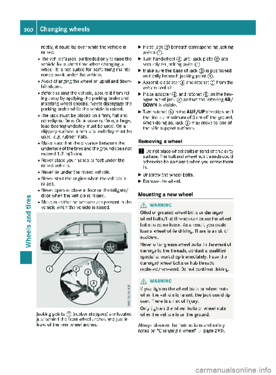
Jacking points :(rubber stoppers) are located
just behind the front wheel arches and just in
front of the rear wheel arches.
XPlace jack ;beneath corresponding jacking
points :.
XTurn handwheel =until jack plate ;sits
securely on jacking point :.
XMake sure the base of jack ;is positioned
vertically beneath jacking point :.
XAssemble adapter?and ratchet Afrom the
vehicle tool kit.
XPlace adapter ?and ratchet Aon the hex-
agon nut of jack ;so that the lettering AB/
DOWN is visible.
XTurn ratchet Ain the AUF/UP direction until
the tire is a maximum of 3 cm off the ground.
When doing so, jack ;may move to one of
the side support surfaces.
Removing a wheel
!Do not place wheel bolts in sand or on a dirty
surface. The bolt and wheel hub threads could
otherwise be damaged when you screw them
in.
XUnscrew the wheel bolts.
XRemove the wheel.
Mounting a new wheel
GWARNING
Oiled or greased wheel bolts or damaged
wheel bolts/hub threads can cause the wheel bolts to come loose. As a result, you could
lose a wheel while driving. There is a risk of
accident.
Never oil or grease wheel bolts. In the event of
damage to the threads, contact a qualified
specialist workshop immediately. Have the
damaged wheel bolts or hub threads
replaced/renewed. Do not continue driving.
GWARNING
If you tighten the wheel bolts or wheel nuts
when the vehicle is raised, the jack could tip
over. There is a risk of injury.
Only tighten the wheel bolts or wheel nuts
when the vehicle is on the ground.
Always observe the instructions and safety
notes on "Changing a wheel" (
Ypage 298).
300Changing wheels
Wheels and tires