air filter MERCEDES-BENZ ML320 1997 Complete Repair Manual
[x] Cancel search | Manufacturer: MERCEDES-BENZ, Model Year: 1997, Model line: ML320, Model: MERCEDES-BENZ ML320 1997Pages: 4133, PDF Size: 88.89 MB
Page 3775 of 4133

AP15.10-P-1580GHReplace spark plugs
1.7.97
ENGINE
112.942 in MODEL 163.154
ENGINE
112.970 in MODEL 163.157
ENGINE
113.942 in MODEL 163.172
ENGINE
113.981 in MODEL 163.174
ENGINE
113.965 in MODEL 163.175
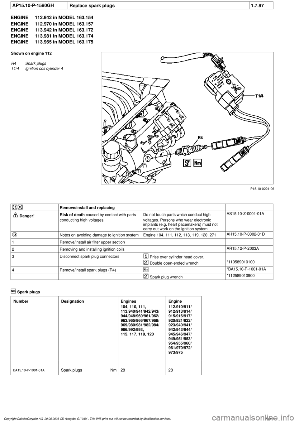
P15.10-0221-06
Shown on engine 112
R4
Spark plugs
T1/4
Ignition coil cylinder 4
Remove/install and replacing
Danger!
Risk of death
caused by contact with parts
conducting high voltages.
Do not touch parts which conduct high
voltages. Persons who wear electronic
implants (e.g. heart pacemakers) must not
carry out work on the ignition system.
AS15.10-Z-0001-01A
Notes on avoiding damage to ignition system
Engine 104, 111, 112, 113, 119, 120, 271
AH15.10-P-0002-01D
1
Remove/install air filter upper section
2
Removing and installing ignition coils
AR15.12-P-2003A
3
Disconnect spark plug connectors
Prise over cylinder head cover.
Double open-ended wrench
*110589010100
4
Remove/install spark plugs (R4)
*BA15.10-P-1001-01A
Spark plug wrench
*112589010900
Spark plugs
Number
Designation
Engines
104, 110, 111,
113.940/941/942/943/
944/948/960/961/962/
963/965/966/967/968/
969/980/981/982/984/
986/992/993,
115, 117, 119, 120
Engine
112.910/911/
912/913/914/
915/916/917/
920/921/922/
923/940/941/
942/943/944/
945/946/947/
949/951/953/
954/955/960/
961/970/972/
973/975
BA15.10-P-1001-01A
Spark plugs
Nm
2828
Copyright DaimlerChrysler AG 20.05.2006 CD-Ausgabe G/10/04 . This WIS print-out will not be recorde
d by Modification services.
Page 1
Page 3836 of 4133

Measures for slightly sludged engine:
Oil and filter change. Purge engine, i.e. normal engine operation
in neutral, or while driving, using oil from Sheet 229.3, 228.3, or
228.5. Drain off scavenging oil after purging process (approx. 1
hour). Repeat purging process if necessary. Refill using engine oil
from Sheet 229.3, or 229.1. The first oil change after clearing the
sludge should be performed after approx. 10,000 km or beforehand;
when doing so use engine oil from Sheet 229.3.
Measures for severely sludged engine:
Engines with severe oil sludging and caking onto engine parts
and into bores have to be dismantled and mechanically cleaned.
Tough sludge residue must not enter the clean side of the oil circuit,
as otherwise, e.g. the piston oil spray and the hydraulic
compensation elements may have their functionality impaired. Refill
using engine oil from Sheet 229.3, or 229.1.
The first oil change after sludging should be performed after approx.
10,000 km; when doing so use engine oil from
Sheet 229.3.
Warranty/goodwill regulations
If in combination with engine oil sludging a warranty/goodwill claim is
submitted, then a regular documentation of maintenance must be
presented. The ASSYST printout is to be filed carefully for further
reference.
Oil sludging in combination with an exceeded oil change interval, or
because of special additives in the fuel/engine oil are costs to be
borne by the customer.
Copyright DaimlerChrysler AG 20.05.2006 CD-Ausgabe G/10/04 . This WIS print-out will not be recorde
d by Modification services.
Page 2
Page 3989 of 4133

AR40.15-P-0080A
Remove/install wheel sensor
1.4.99
MODELS
210.074 /274 with CODE (475) Tire pressure indicator
MODELS
211 with CODE (475) Tire pressure indicator
MODELS
215 with CODE (475) Tire pressure indicator
MODELS
220 with CODE (475) Tire pressure indicator
MODELS
230 with CODE (475) Tire pressure indicator
MODELS
240 with CODE (475) Tire pressure indicator
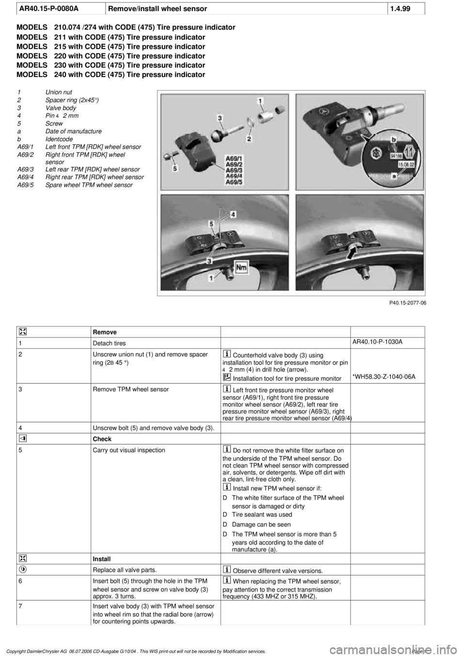
P40.15-2077-06
1
Union nut
2
Spacer ring (2x45°)
3
Valve body
4
Pin
4
2 mm
5
Screw
a
Date of manufacture
b
Identcode
A69/1
Left front TPM [RDK] wheel sensor
A69/2
Right front TPM [RDK] wheel
sensor
A69/3
Left rear TPM [RDK] wheel sensor
A69/4
Right rear TPM [RDK] wheel sensor
A69/5
Spare wheel TPM wheel sensor
Remove
1
Detach tires
AR40.10-P-1030A
2
Unscrew union nut (1) and remove spacer
ring (2
B
45 °)
Counterhold valve body (3) using
installation tool for tire pressure monitor or pin
4
2 mm (4) in drill hole (arrow).
Installation tool for tire pressure monitor
*WH58.30-Z-1040-06A
3
Remove TPM wheel sensor
Left front tire pressure monitor wheel
sensor (A69/1), right front tire pressure
monitor wheel sensor (A69/2), left rear tire
pressure monitor wheel sensor (A69/3), right
rear tire pressure monitor wheel sensor (A69/4)
4
Unscrew bolt (5) and remove valve body (3).
Check
5
Carry out visual inspection
Do not remove the white filter surface on
the underside of the TPM wheel sensor. Do
not clean TPM wheel sensor with compressed
air, solvents, or detergents. Wipe off dirt with
a clean, lint-free cloth only.
Install new TPM wheel sensor if:
D
The white filter surface of the TPM wheel
sensor is damaged or dirty
D
Tire sealant was used
D
Damage can be seen
D
The TPM wheel sensor is more than 5
years old according to the date of
manufacture (a).
Install
Replace all valve parts.
Observe different valve versions.
6
Insert bolt (5) through the hole in the TPM
wheel sensor and screw on valve body (3)
approx. 3 turns.
When replacing the TPM wheel sensor,
pay attention to the correct transmission
frequency (433 MHZ or 315 MHZ).
7
Insert valve body (3) with TPM wheel sensor
into wheel rim so that the radial bore (arrow)
for countering points upwards.
Copyright DaimlerChrysler AG 06.07.2006 CD-Ausgabe G/10/04 . This WIS print-out will not be recorde
d by Modification services.
Page 1