transmission oil MERCEDES-BENZ ML320 1997 Complete Repair Manual
[x] Cancel search | Manufacturer: MERCEDES-BENZ, Model Year: 1997, Model line: ML320, Model: MERCEDES-BENZ ML320 1997Pages: 4133, PDF Size: 88.89 MB
Page 3606 of 4133

BT27.40-P-0003-01A
Magnet in oil pan, new part
TRANSMISSION
722.6## ## as of 2871384 as of 17.4.01,
722.7## ## as of 0153700 as of 9.7.01
P27.40-2027-01
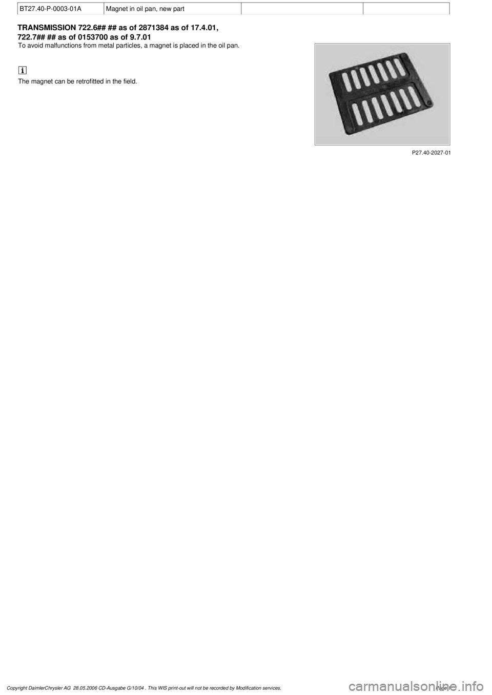
To avoid malfunctions from metal particles, a magnet is placed in the oil pan.
The magnet can be retrofitted in the field.
Copyright DaimlerChrysler AG 28.05.2006 CD-Ausgabe G/10/04 . This WIS print-out will not be recorde
d by Modification services.
Page 1
Page 3717 of 4133

BT27.20-P-0001-01A
Oil drain plug on torque converter deleted
Transmission 722.6
k
TRANSMISSION
722.6## /6## ## as of 1772285 as of 22.9.99
For reasons of cost, the oil drain plug on the torque converter has
been deleted for all transmission variants.
Copyright DaimlerChrysler AG 28.05.2006 CD-Ausgabe G/10/04 . This WIS print-out will not be recorde
d by Modification services.
Page 1
Page 3722 of 4133

BT27.10-P-0006-01W
Oil pan and overflow tube modified
k
TRANSMISSION
722.901
P27.10-2139-06
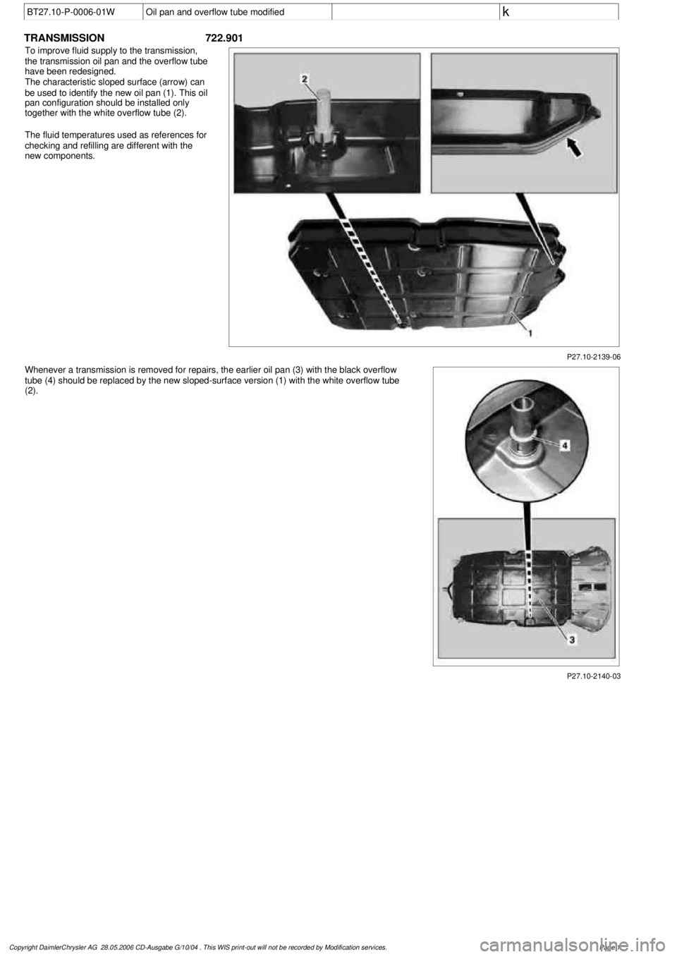
To improve fluid supply to the transmission,
the transmission oil pan and the overflow tube
have been redesigned.
The characteristic sloped surface (arrow) can
be used to identify the new oil pan (1). This oil
pan configuration should be installed only
together with the white overflow tube (2).
The fluid temperatures used as references for
checking and refilling are different with the
new components.
Whenever a transmission is removed for repairs, the earlier oil pan (3) with the black overflow
tube (4) should be replaced by the new sloped-surface version (1) with the white overflow tube
(2).
P27.10-2140-03
Copyright DaimlerChrysler AG 28.05.2006 CD-Ausgabe G/10/04 . This WIS print-out will not be recorde
d by Modification services.
Page 1
Page 3742 of 4133

AR03.10-P-7311BV
Remove/install piston rings
2.7.97
ENGINE
113 in MODEL 129, 163, 202, 203, 208, 209, 210, 211, 215, 220, 230
ENGINE
112 /945, 113.962 /982
P03.10-2022-06
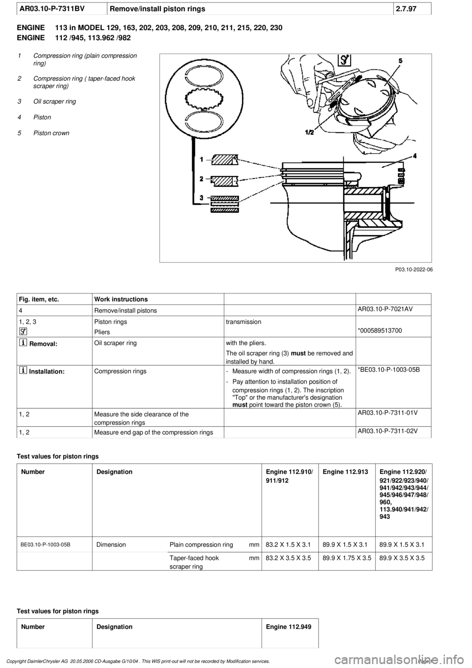
1
Compression ring (plain compression
ring)
2
Compression ring ( taper-faced hook
scraper ring)
3
Oil scraper ring
4
Piston
5
Piston crown
Fig. item, etc.
Work instructions
4
Remove/install pistons
AR03.10-P-7021AV
1, 2, 3
Piston rings
transmission
Pliers
*000589513700
Removal:
Oil scraper ring
with the pliers.
The oil scraper ring (3)
must be removed and
installed by hand.
Installation:
Compression rings
-
Measure width of compression rings (1, 2).
*BE03.10-P-1003-05B
-
Pay attention to installation position of
compression rings (1, 2). The inscription
"Top" or the manufacturer's designation
must
point toward the piston crown (5).
1, 2
Measure the side clearance of the
compression rings
AR03.10-P-7311-01V
1, 2
Measure end gap of the compression rings
AR03.10-P-7311-02V
Test values for piston rings
Number
Designation
Engine 112.910/
911/912
Engine 112.913
Engine 112.920/
921/922/923/940/
941/942/943/944/
945/946/947/948/
960,
113.940/941/942/
943
BE03.10-P-1003-05B
Dimension
Plain compression ring
mm
83.2 X 1.5 X 3.189.9 X 1.5 X 3.189.9 X 1.5 X 3.1
Taper-faced hook
scraper ring
mm
83.2 X 3.5 X 3.5
89.9 X 1.75 X 3.5
89.9 X 3.5 X 3.5
Test values for piston rings
Number
Designation
Engine 112.949
Copyright DaimlerChrysler AG 20.05.2006 CD-Ausgabe G/10/04 . This WIS print-out will not be recorde
d by Modification services.
Page 1
Page 3745 of 4133

2.1
Detach automatic transmission from engine
Models 463.206/ 209/ 232/ 233/ 240/ 241
AR27.10-P-0500BD
Models 463.243/ 244/ 245/ 246/ 247/ 248/
249/ 250/ 254
AR27.10-P-0500GA
Model 230.475
AR27.10-P-0500R
Model 230.474
Model 220 without 4MATIC
AR27.10-P-0500I
Model 220 with 4MATIC
AR27.10-P-0500IW
Models 129, 170, 202, 208, 210
AR27.10-P-0500B
Model 203 without 4MATIC, 209 with Engine
112,113
AR27.10-P-0500P
Model 203 with 4MATIC
AR27.10-P-0500PW
Model 211.061/065/070
AR27.10-P-0500T
Model 163
AR27.10-P-0500GH
2.2
Detach manual transmission from engine
Models 129, 202, 210
AR26.10-P-0020A
Models 203, 209 with Engine 112
AR26.10-P-0020P
Model 211.061
AR26.10-P-0020T
Model 208 with transmission 716.662/622
AR26.10-P-0020E
Model 170,
Model 208 with transmission 716.663
AR26.10-P-0020D
3
Detach top part of oil pan
Models 463.206/ 209/ 232/ 233/ 240/ 241/
243/ 244/ 245/ 246/ 247/ 248/ 249/ 250/ 254
AR01.45-P-7500FG
Model 230.474/
AR01.45-P-7500R
Model 220 without 4MATIC
AR01.45-P-7500I
Model 220 with 4MATIC
AR01.45-P-7500IW
Model 210 with 4MATIC
AR01.45-P-7500FA
Model 210 without 4MATIC
AR01.45-P-7500F
Models 202, 208
AR01.45-P-7500FC
Model 203 without 4MATIC, 209 with Engine
112,113
AR01.45-P-7500PV
Model 203 with 4MATIC
AR01.45-P-7500PW
Models 211.061/065/070
AR01.45-P-7500TV
Model 170
AR01.45-P-7500SV
Model 163
AR01.45-P-7500FB
Model 129
AR01.45-P-7500FD
4
Take off cylinder head
Remove intake manifold with complete
wiring loom during this step.
Models 463.206/ 209/ 232/ 233/ 240/ 241/
243/ 244/ 245/ 246/ 247/ 248/ 249/ 250/ 254
AR01.30-P-5800GV
Engine 112 in model 129 and engine 113 in
models 129, 202, 208, 210
AR01.30-P-5800B
Engine 112 in models 170, 202, 208, 210,
220 and engine 113 in models 220,
230.474 /475
AR01.30-P-5800BA
Model 163
AR01.30-P-5800MV
Models 203, 209 with engine 112, 113
Models 211.061/065/070
AR01.30-P-5800PV
5
Remove oil pump
Push back chain tensioner for this step
and take off chain.
All except models 203, 209, 211.061/065/070,
220 without 4MATIC, 230.474 /475
AR18.10-P-6020B
Model 203 without 4MATIC, 209,
211.061/065/070
AR18.10-P-6020PV
Model 203 with 4MATIC, model 220 with
4MATIC
AR18.10-P-6020PW
Model 230.474/475
AR18.10-P-6020R
6
Remove conrod bearing cap (5)
For this step, mark conrod (4) and
connecting rod bearing cap (5) on one side
relative to each other.
7
Remove conrod (4) together with pistons (3)
by lifting up and out
If pistons have been used (3), the arrows
indicating the direction of the travel and the
markings on the pistons may no longer be
visible due to carbon deposits. For this
reason, remove the carbon deposits from the
pistons. If the arrows indicating direction of
travel on the pistons are no longer
recognizable, these must be re-marked.
8
Remove circlip (1) of piston pin (2)
Do not damage piston (3). Place a clean
cloth underneath.
9
Press out piston pin (2)
Installing
10
Assign piston (3) to cylinder bore
AR03.10-P-7021-02BV
Copyright DaimlerChrysler AG 20.05.2006 CD-Ausgabe G/10/04 . This WIS print-out will not be recorde
d by Modification services.
Page 2
Page 3757 of 4133

3.1
Remove viscous fan (1)
Engine 112.942 /970 and 113.942.
Right-hand thread!
AR20.40-P-5660C
3.2
Remove electric fan
Only Engine 113.965 /981.
AR20.40-P-5000GH
4.1
Pull off plate clamps of fan shroud (2)
Only for Engine 112.942, from 5/98.
5.1
Remove fan shroud (3)
Only for Engine 112.942 /970 und
113.942. Unscrew the bolts at bottom of fan
shroud for this step
Installation:
If installing a new radiator
with integral power steering pump oil cooler, a
new fan shroud is required if a radiator
without integral oil cooler was previously
installed.
6
Remove headlamp (7).
AR82.10-P-4730GH
7
Remove radiator crossmember (8)
AR62.30-P-2300GH
8
Detach coolant line (4, 6) and expansion
reservoir coolant line (5) at the radiator
Installation:
Replace the hose clamps on
the radiator fitting for the coolant hose, as
they could cause damage to the screw/thread.
Hose clamp
*BA20.20-P-1004-01A
9
Remove the rubber seal on radiator (9)
10.1
Remove oil line (return line of radiator
!
power steering pump expansion reservoir)
(18) and oil line (feed line of steering gear
!
radiator) (19)
From 5/98 only, seal off the connections.
Set of plugs
*129589009100
11
Unscrew ATF lines (10) at the radiator
Seal off the connections.
*BA20.20-P-1001-01A
*BA20.20-P-1003-01A
Set of plugs
*129589009100
12.1
Detach the connector from the fan and
remove the fan grille (11)
Only for Engine 112.942 /970 and 113.942.
13
Unscrew the condenser from the radiator
Do not disconnect the lines.
14
Remove fasteners (20) and damper rubber
(21)
The damper rubber (21) is designed to
prevent possible vibrations between the
condenser and radiator (15) during off-road
driving.
15
Remove air conditioning system fluid
reservoir (14) from the radiator
Place aside with the lines connected.
Detach the condenser from the radiator.
16
Remove radiator (15)
When installing, the spigots on the
radiator must be inserted in the rubber
grommets in the bottom crossmember.
Installation:
On Model 163.154 with
Engine 112.942 before VIN end number
043553, when installing a new radiator with
integral power steering pump oil cooler,
additional operations are required, if they
have not already been carried out:
#
v
Retrofit the bracket for the oil cooler line of
the power steering pump
SM46.30-P-0002A
k
Radiator with integral oil cooler for the power
steering pump
BT20.20-P-0001-01A
17
Detach air guides (12)
Replace the clamps on air guides (13).
18
Install in the reverse order
19
Pour in coolant
AR20.00-P-1142HA
20
Check the headlamp setting and correct if
necessary
e
Check and adjust the headlamp setting
AP82.10-P-8260GH
Danger!
Risk of accident
caused by vehicle starting
off when engine is running.
Risk of injury
caused by contusions and burns when
working in engine during starting procedure
Secure the vehicle to prevent it from moving.
Wear closed and snug-fitting work clothes.
Do not grasp hot or rotating parts.
AS00.00-Z-0005-01A
21
Check the oil level in the automatic
transmission and correct if necessary
AR27.00-P-0101A
22
Check the cooling system for leaks
AR20.00-P-1010HA
Radiator, coolant hoses
Copyright DaimlerChrysler AG 12.05.2006 CD-Ausgabe G/10/04 . This WIS print-out will not be recorde
d by Modification services.
Page 2