ad blue MERCEDES-BENZ ML320 1997 Complete User Guide
[x] Cancel search | Manufacturer: MERCEDES-BENZ, Model Year: 1997, Model line: ML320, Model: MERCEDES-BENZ ML320 1997Pages: 4133, PDF Size: 88.89 MB
Page 1911 of 4133
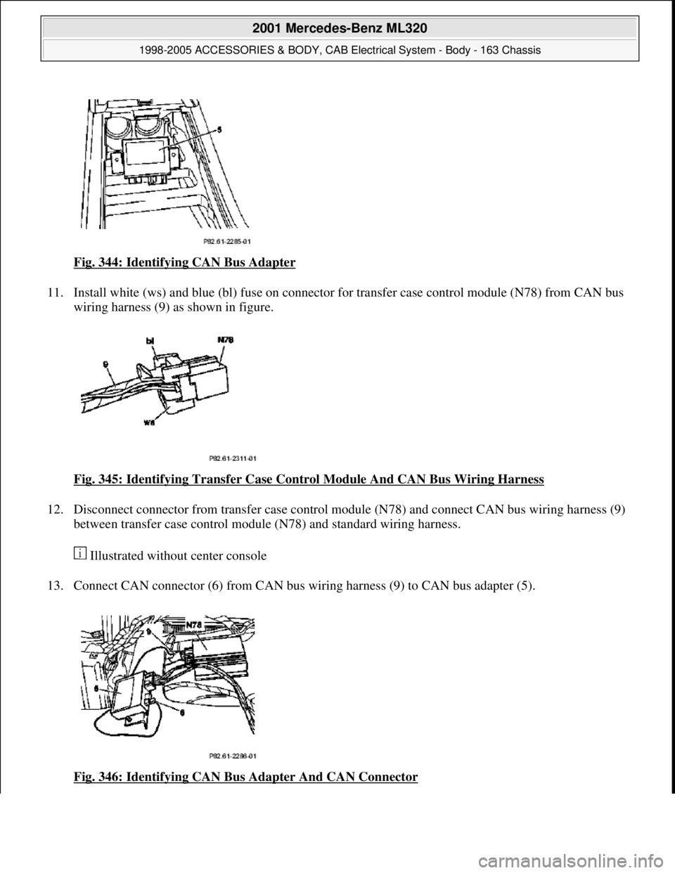
Fig. 344: Identifying CAN Bus Adapter
11. Install white (ws) and blue (bl) fuse on connector for transfer case control module (N78) from CAN bus
wiring harness (9) as shown in figure.
Fig. 345: Identifying Transfer Case Cont rol Module And CAN Bus Wiring Harness
12. Disconnect connector from transfer case control module (N78) and connect CAN bus wiring harness (9)
between transfer case control module (N78) and standard wiring harness.
Illustrated without center console
13. Connect CAN connector (6) from CAN bus wiring harnes s (9) to CAN bus adapter (5).
Fig. 346: Identifying CAN Bu s Adapter And CAN Connector
2001 Mercedes-Benz ML320
1998-2005 ACCESSORIES & BODY, CAB Electr ical System - Body - 163 Chassis
me
Saturday, October 02, 2010 3:30:13 PMPage 416 © 2006 Mitchell Repair Information Company, LLC.
Page 1922 of 4133
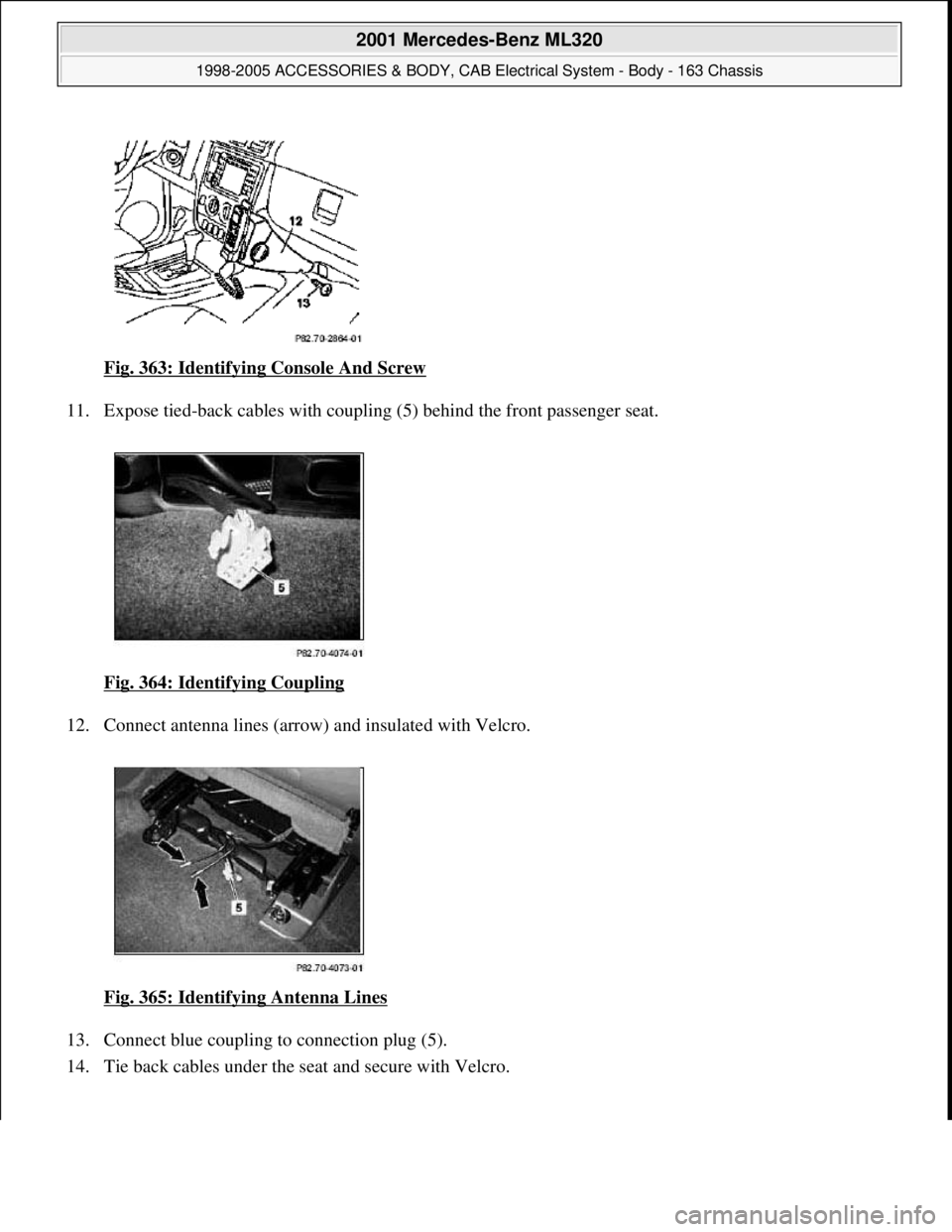
Fig. 363: Identifying Console And Screw
11. Expose tied-back cables with coupli ng (5) behind the front passenger seat.
Fig. 364: Identifying Coupling
12. Connect antenna lines (arrow ) and insulated with Velcro.
Fig. 365: Identifying Antenna Lines
13. Connect blue coupling to connection plug (5).
14. Tie back cables under the se at and secure with Velcro.
2001 Mercedes-Benz ML320
1998-2005 ACCESSORIES & BODY, CAB Electr ical System - Body - 163 Chassis
me
Saturday, October 02, 2010 3:30:13 PMPage 427 © 2006 Mitchell Repair Information Company, LLC.
Page 1923 of 4133
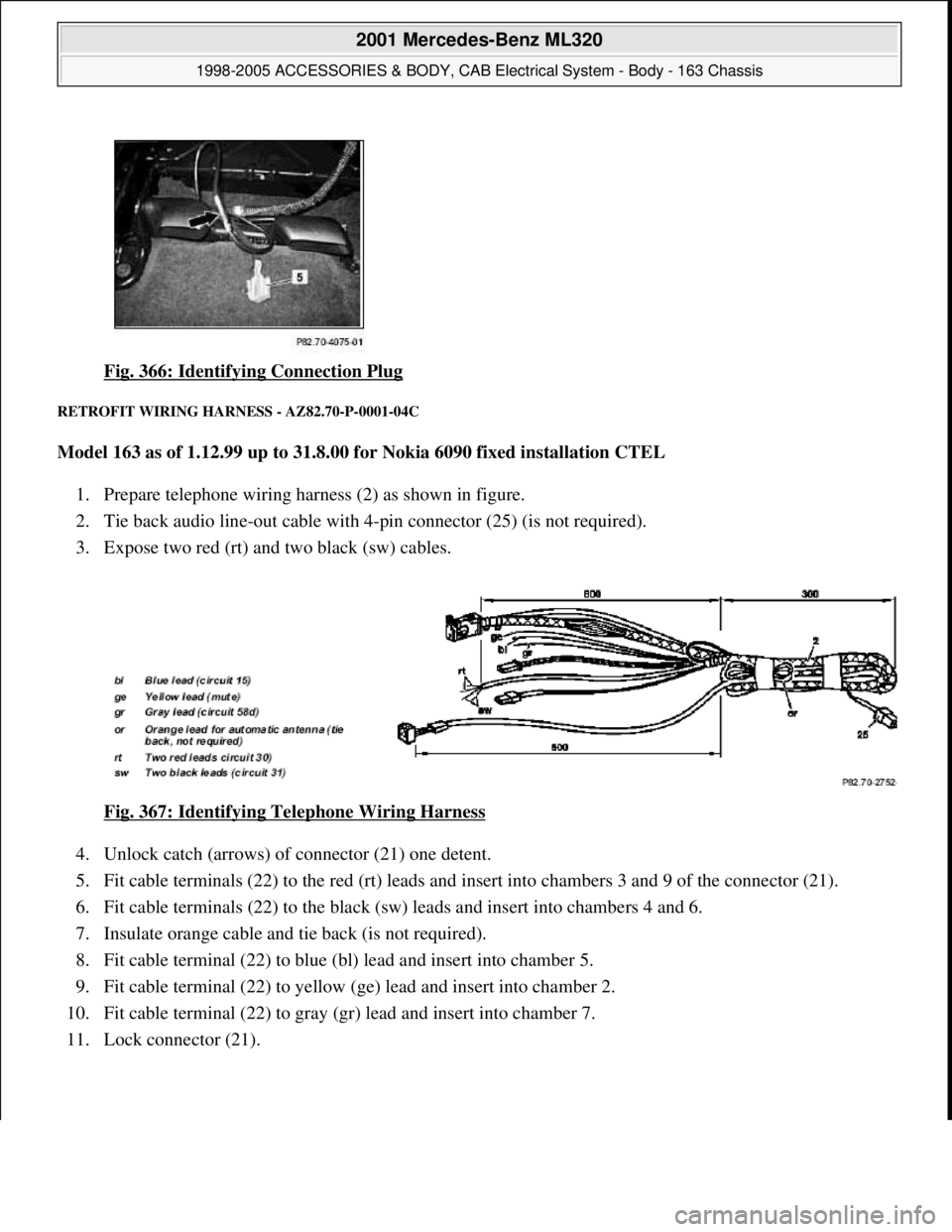
Fig. 366: Identifying Connection Plug
RETROFIT WIRING HARNESS - AZ82.70-P-0001-04C
Model 163 as of 1.12.99 up to 31.8.00 for Nokia 6090 fixed installation CTEL
1. Prepare telephone wiring harness (2) as shown in figure.
2. Tie back audio line-out cable with 4-pin connector (25) (is not required).
3. Expose two red (rt) and two black (sw) cables.
Fig. 367: Identifying Telephone Wiring Harness
4. Unlock catch (arrows) of connector (21) one detent.
5. Fit cable terminals (22) to the red (rt) leads and insert into chambers 3 and 9 of the connector (21).
6. Fit cable terminals (22) to the black (sw) leads and insert into chambers 4 and 6.
7. Insulate orange cable and tie back (is not required).
8. Fit cable terminal (22) to blue (bl) lead and insert into chamber 5.
9. Fit cable terminal (22) to yellow (ge) lead and insert into chamber 2.
10. Fit cable terminal (22) to gray (gr) lead and insert into chamber 7.
11. Lock connector (21).
2001 Mercedes-Benz ML320
1998-2005 ACCESSORIES & BODY, CAB Electrical System - Body - 163 Chassis
me
Saturday, October 02, 2010 3:30:13 PMPage 428 © 2006 Mitchell Repair Information Company, LLC.
Page 1926 of 4133
1. Shop-make wiring harness as specified in steps 2 to 6.
2. Cut cables at connection adapter (20) to length of approx. 150 mm.
3. Install terminal (22) on five fr ee lead ends of connection adapter (20) (not to green lead).
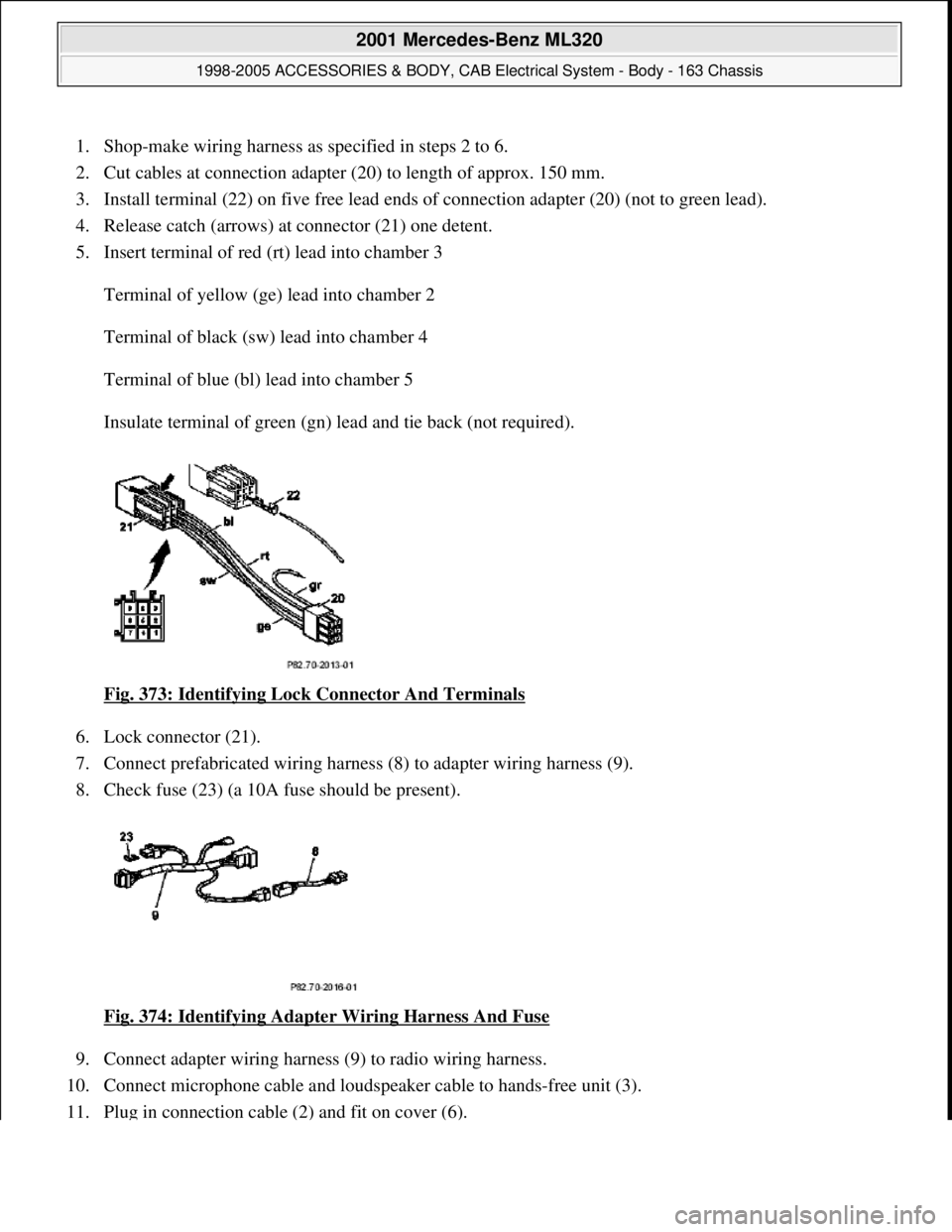
4. Release catch (arrows) at connector (21) one detent.
5. Insert terminal of red (rt) lead into chamber 3
Terminal of yellow (ge) lead into chamber 2
Terminal of black (sw) lead into chamber 4
Terminal of blue (bl) lead into chamber 5
Insulate terminal of green (gn) lead and tie back (not required).
Fig. 373: Identifying Lock Connector And Terminals
6. Lock connector (21).
7. Connect prefabricated wiring harness (8) to adapter wiring harness (9).
8. Check fuse (23) (a 10A fuse should be present).
Fig. 374: Identifying Adapter Wiring Harness And Fuse
9. Connect adapter wiring harness (9) to radio wiring harness.
10. Connect microphone cable and loudspeaker cable to hands-free unit (3).
11. Plu
g in connection cable (2) and fit on cover (6).
2001 Mercedes-Benz ML320
1998-2005 ACCESSORIES & BODY, CAB Electr ical System - Body - 163 Chassis
me
Saturday, October 02, 2010 3:30:13 PMPage 431 © 2006 Mitchell Repair Information Company, LLC.
Page 1934 of 4133
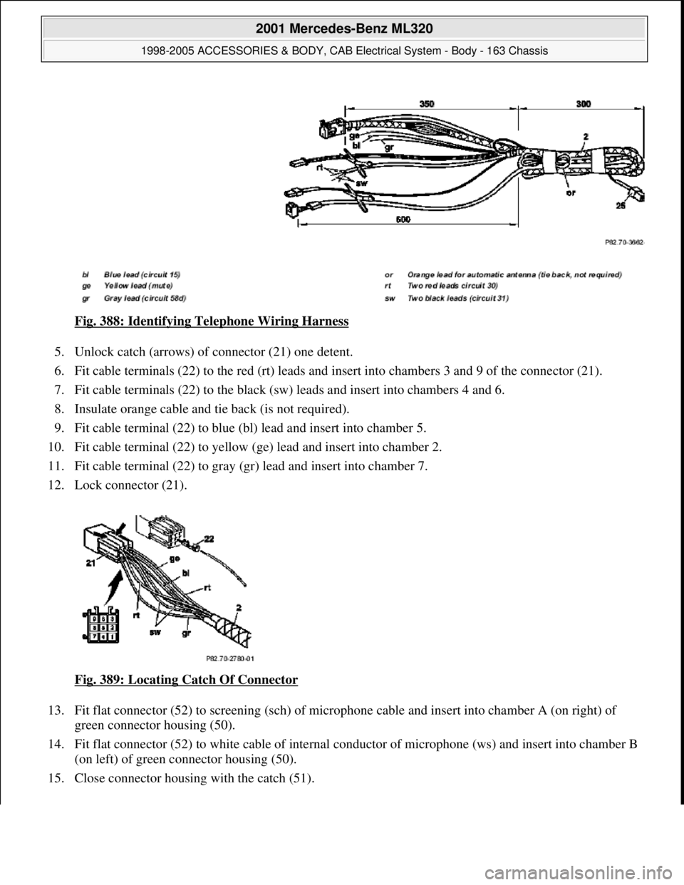
Fig. 388: Identifying Telephone Wiring Harness
5. Unlock catch (arrows) of connector (21) one detent.
6. Fit cable terminals (22) to the red (rt) leads and insert into chambers 3 and 9 of the connector (21).
7. Fit cable terminals (22) to the black (sw) leads and insert into chambers 4 and 6.
8. Insulate orange cable and tie back (is not required).
9. Fit cable terminal (22) to blue (bl) lead and insert into chamber 5.
10. Fit cable terminal (22) to yellow (ge) lead and insert into chamber 2.
11. Fit cable terminal (22) to gray (gr) lead and insert into chamber 7.
12. Lock connector (21).
Fig. 389: Locating Catch Of Connector
13. Fit flat connector (52) to screening (sch) of microphone cable and insert into chamber A (on right) of
green connector housing (50).
14. Fit flat connector (52) to white cable of internal conductor of microphone (ws) and insert into chamber B
(on left) of green connector housing (50).
15. Close connector housin
g with the catch (51).
2001 Mercedes-Benz ML320
1998-2005 ACCESSORIES & BODY, CAB Electrical System - Body - 163 Chassis
me
Saturday, October 02, 2010 3:30:13 PMPage 439 © 2006 Mitchell Repair Information Company, LLC.
Page 2080 of 4133
Crankshaft Position Sensor DIY
hopefully this will help others with what appears to be a common stalling issue in the ML series.
Location:
--------
It's on the rear of the engine where the engine mates with the tranny on the driver's side. There are 2
types. Be sure to get the correct one
Here it is:
1) Get
CPS
at dealer, its a VIN specific part. $125 from my local stealer.
2) Tools needed: Socket screwdriver, Good lighting (portable) shop lights, size 8 outside torx socket,
maybe a ratche
t and extentions depending on your flexibility, magnetic part retrieval tool (skip this at
your peril), bath towel, and long sleeve shirt, step stool, blue thread locker (optional)
3) Open hood and remove engine cover, it just pulls off and on
4) Set wor
k light(s) toward back of engine, lighting behind drivers cylinder head
5) Set bath towel on front of ML to kneel on of your knees will die, wearing long sleeve shirt or your
wrists will be cut.
6) Climb up on towel and look behind engine from above and
right (see .jpg), finding torx attachment
holding your
CPS
.
7) Remove torx screw and pull out
CPS
, disconnect one way connector (wiring)
8) Replace with new (leaving wire detached for now)
9) This is the hardest step by far, and requires patience and fl exibility. Apply some thread locker and
insert screw and start the threads. Tighten with torx on socket screwdriver. This step took about 1/2
hour and numerous dropped screws and retrievals with mag tool.
10) Attach wiring to
CPS
11) Reinstall engine cov
er
12) Clean up tools, towel and lights and everything
13) Drink beer and toast yourself for saving yourself at least $100 and a day of your time dropping off
and picking up cars at shop
Hope this helps someone in the community.
Dickie
00 ML 32
0
Page 2233 of 4133

11
Check oil level approx. 5 min. after switching
off warm engine
Insert oil dipstick up to the stop and keep
to a residence time of at least 3 seconds.
Model 163, 210 with Engine 612
*BE18.00-P-1001-02B
Model 203, Model 209 with Engine 612
On Model 203, Model 209 after oil level
check pay attention to correct seating of the
cap, otherwise it could result in engine
damage.
Only Model 203:
Up to engine end number: 134 163 oil level
MAX. 135
mm,
MIN 110
mm.
As of engine end number: 134 164 oil level
MAX. 124,5
mm,
MIN 99,5
mm.
Measuring rod
*120589072100
12
Install trim panel of cylinder head cover
AR01.20-P-5014-02B
*BA01.20-P-1002-01A
*BA01.20-P-1003-01A
Test values for engine lubrication - general
Number
Designation
Engine
612.961
Engine
612.963
BE18.00-P-1001-02B
Dipstick marking
Color red
t
1
Color black
t
2
Color green
t
3
Color gentian blue
t
4
Numbers on handle
Number
6020760206
Round handle
Color
--
Bottle opener-shaped
handle
Color
11
Designation
Engine
612.961/962/
963/965/966,
613.961
Engine
612.967
Engine
612.990
BA01.45-P-1003-01A
Oil drain plug at oil pan
M12
Nm
---
M14
Nm
303030
Engine lubrication, oil filter
Number
Designation
Engine
612.961/962/
963/967/990,
613.960/961
BA18.20-P-1002-01G
Screw cap at oil filter
Nm
25
Crankcase ventilation, cylinder head cover
Number
Designation
Engine
612.961/
962/967
Engine
612.963
Engine
612.990
Copyright DaimlerChrysler AG 20.05.2006 CD-Ausgabe G/10/04 . This WIS print-out will not be recorde
d by Modification services.
Page 2
Page 2333 of 4133
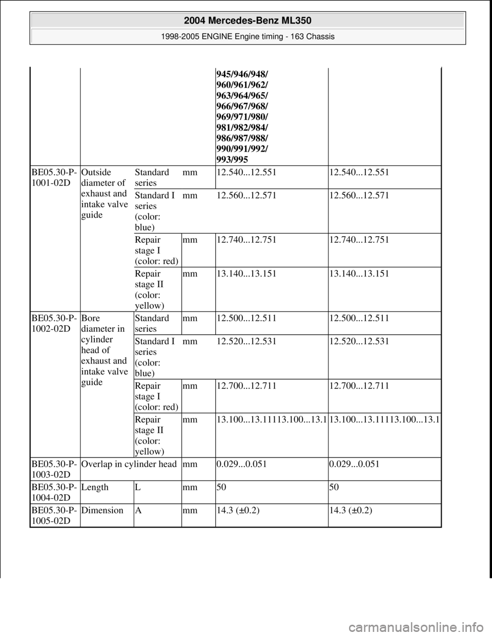
945/946/948/
960/961/962/
963/964/965/
966/967/968/
969/971/980/
981/982/984/
986/987/988/
990/991/992/
993/995
BE05.30-P-
1001-02DOutside
diameter of
exhaust and
intake valve
guideStandard
seriesmm12.540...12.55112.540...12.551
Standard I
series
(color:
blue)mm12.560...12.57112.560...12.571
Repair
stage I
(color: red)mm12.740...12.75112.740...12.751
Repair
stage II
(color:
yellow)mm13.140...13.15113.140...13.151
BE05.30-P-
1002-02DBore
diameter in
cylinder
head of
exhaust and
intake valve
guideStandard
seriesmm12.500...12.51112.500...12.511
Standard I
series
(color:
blue)mm12.520...12.53112.520...12.531
Repair
stage I
(color: red)mm12.700...12.71112.700...12.711
Repair
stage II
(color:
yellow)mm13.100...13.11113.100...13.113.100...13.11113.100...13.1
BE05.30-P-
1003-02DOverlap in cylinder headmm0.029...0.0510.029...0.051
BE05.30-P-
1004-02DLengthLmm5050
BE05.30-P-
1005-02DDimensionAmm14.3 (±0.2)14.3 (±0.2)
2004 Mercedes-Benz ML350
1998-2005 ENGINE Engine timing - 163 Chassis
me
Saturday, October 02, 2010 3:39:38 PMPage 92 © 2006 Mitchell Repair Information Company, LLC.
Page 2336 of 4133
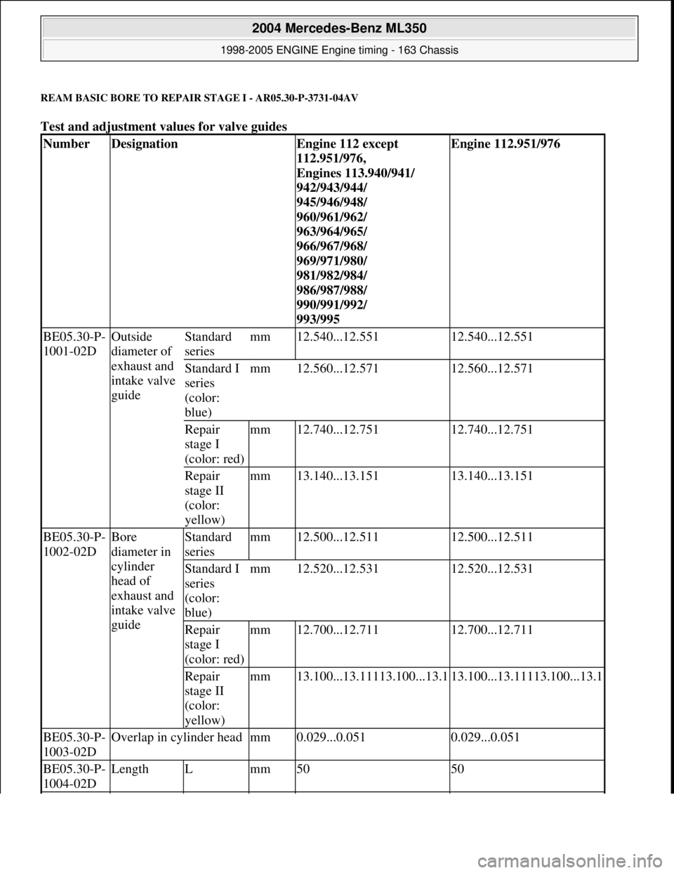
REAM BASIC BORE TO REPAIR STAGE I - AR05.30-P-3731-04AV
Test and adjustment values for valve guides
NumberDesignationEngine 112 except
112.951/976,
Engines 113.940/941/
942/943/944/
945/946/948/
960/961/962/
963/964/965/
966/967/968/
969/971/980/
981/982/984/
986/987/988/
990/991/992/
993/995Engine 112.951/976
BE05.30-P-
1001-02DOutside
diameter of
exhaust and
intake valve
guideStandard
seriesmm12.540...12.55112.540...12.551
Standard I
series
(color:
blue)mm12.560...12.57112.560...12.571
Repair
stage I
(color: red)mm12.740...12.75112.740...12.751
Repair
stage II
(color:
yellow)mm13.140...13.15113.140...13.151
BE05.30-P-
1002-02DBore
diameter in
cylinder
head of
exhaust and
intake valve
guideStandard
seriesmm12.500...12.51112.500...12.511
Standard I
series
(color:
blue)mm12.520...12.53112.520...12.531
Repair
stage I
(color: red)mm12.700...12.71112.700...12.711
Repair
stage II
(color:
yellow)mm13.100...13.11113.100...13.113.100...13.11113.100...13.1
BE05.30-P-
1003-02DOverlap in cylinder headmm0.029...0.0510.029...0.051
BE05.30-P-
1004-02DLengthLmm5050
2004 Mercedes-Benz ML350
1998-2005 ENGINE Engine timing - 163 Chassis
me
Saturday, October 02, 2010 3:39:38 PMPage 95 © 2006 Mitchell Repair Information Company, LLC.
Page 2339 of 4133
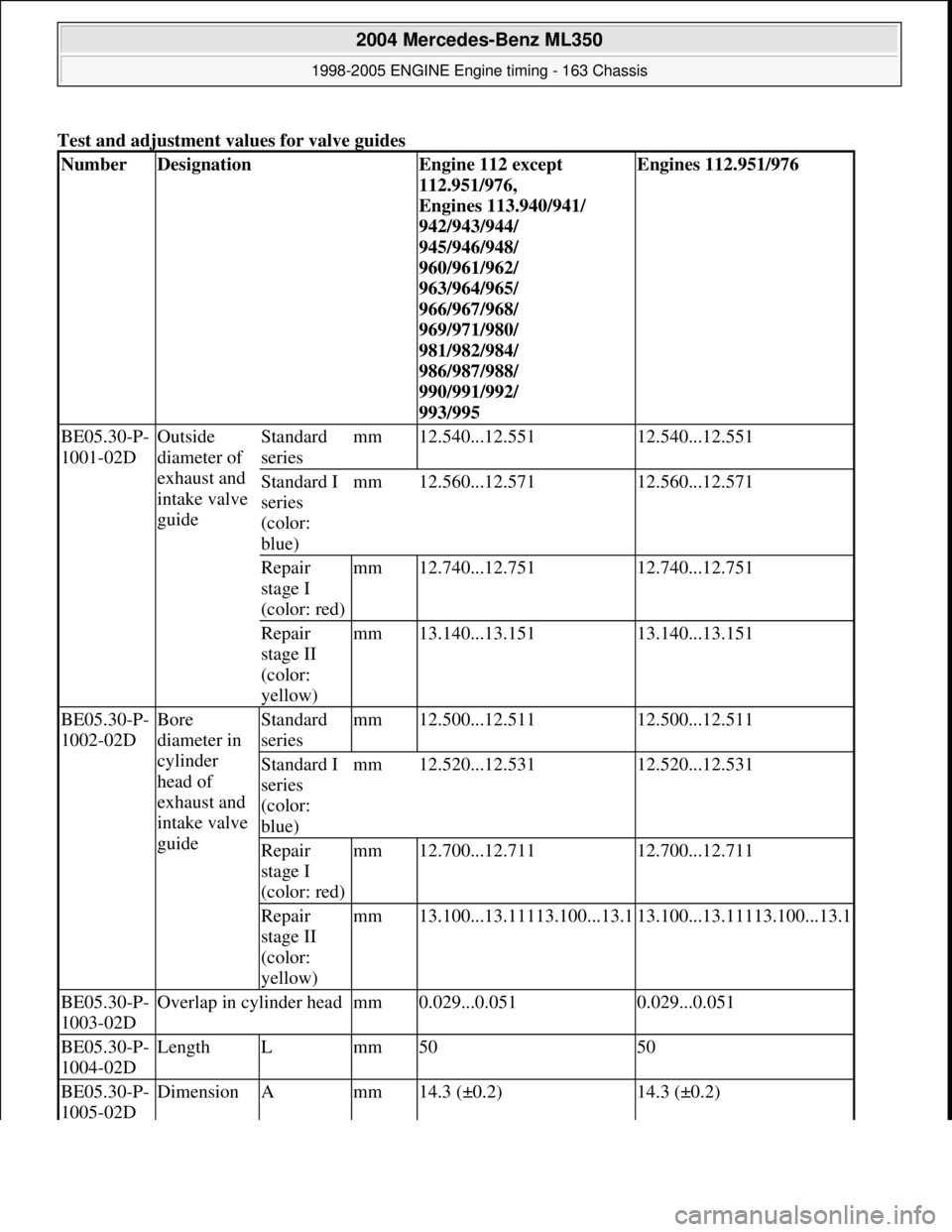
Test and adjustment values for valve guides
NumberDesignationEngine 112 except
112.951/976,
Engines 113.940/941/
942/943/944/
945/946/948/
960/961/962/
963/964/965/
966/967/968/
969/971/980/
981/982/984/
986/987/988/
990/991/992/
993/995Engines 112.951/976
BE05.30-P-
1001-02DOutside
diameter of
exhaust and
intake valve
guideStandard
seriesmm12.540...12.55112.540...12.551
Standard I
series
(color:
blue)mm12.560...12.57112.560...12.571
Repair
stage I
(color: red)mm12.740...12.75112.740...12.751
Repair
stage II
(color:
yellow)mm13.140...13.15113.140...13.151
BE05.30-P-
1002-02DBore
diameter in
cylinder
head of
exhaust and
intake valve
guideStandard
seriesmm12.500...12.51112.500...12.511
Standard I
series
(color:
blue)mm12.520...12.53112.520...12.531
Repair
stage I
(color: red)mm12.700...12.71112.700...12.711
Repair
stage II
(color:
yellow)mm13.100...13.11113.100...13.113.100...13.11113.100...13.1
BE05.30-P-
1003-02DOverlap in cylinder headmm0.029...0.0510.029...0.051
BE05.30-P-
1004-02DLengthLmm5050
BE05.30-P-
1005-02DDimensionAmm14.3 (±0.2)14.3 (±0.2)
2004 Mercedes-Benz ML350
1998-2005 ENGINE Engine timing - 163 Chassis
me
Saturday, October 02, 2010 3:39:38 PMPage 98 © 2006 Mitchell Repair Information Company, LLC.