MERCEDES-BENZ ML320 1997 Complete Repair Manual
ML320 1997
MERCEDES-BENZ
MERCEDES-BENZ
https://www.carmanualsonline.info/img/4/57305/w960_57305-0.png
MERCEDES-BENZ ML320 1997 Complete Repair Manual
Page 3961 of 4133

AD54.30-P-5000-02A
Display instruments controlled via CAN
troubleshooting chart IC
The following display instruments or indicator lamps/ malfunction
indicator lamps receive their information from the traction system
control module (N47) via CAN data buses (an appropriate message
appears in the display on vehicles with multi-function display):
D
Total mileage recorder, trip odometer
D
Electronic speedometer
D
Low brake fluid level/parking brake indicator lamp (except model 163
parking brake indicator lamp only via CAN)
D
Brake pad wear indicator lamp
D
ABS MIL
D
ETS, ASR, ESP indicator lamp
D
ETS, ASR, ESP malfunction indicator lamp
Model 163 only:
The
"Low-Range"
indicator lamp receives its information from the
transfer case control module (N78) via CAN data buses.
The
"Fog lamps"
indicator lamp (only model 163 except
I
) receives
its information from the All-activity module (AAM, N10) via CAN data
buses.
Model 168 only:
The
" Gear indicator "
indicator lamp receives its information from the
gear recognition module (A61) or from automatic clutch control module
(N15/4) via CAN data buses.
The following display instruments or indicator lamps/
malfunction indicator lamps receive their information from the
injection system control module (N3) via CAN data buses (an
appropriate message appears in the display on vehicles with
multi-function display):
D
Tachometer
D
Low engine oil level lamp
D
Engine coolant temperature
D
Preglow indicator lamp (diesel only)
D
Vehicle speed warning
D
Vehicle speed limit warning
D
Severe leak warning (
I
only), the fuel reserve indicator lamp
(A1e4) flashes
D
Active Service System (ASSYST):
D
Oil condition
D
Oil level
D
Oil temperature
D
Mass volumetric efficiency (load moment)
D
Engine speed, engine coolant temperature
Copyright DaimlerChrysler AG 05.06.2006 CD-Ausgabe G/10/04 . This WIS print-out will not be recorde
d by Modification services.
Page 1
Page 3986 of 4133
AR20.40-P-5660C
Remove/install viscous fan clutch
12.6.96
ENGINE
112 in MODEL 210, 202, 163.154 /157, 129
ENGINE
113 in MODEL 210, 208, 202, 163.172, 129
ENGINE
112.945 in MODEL 463.209 /232 /233 /244 /245 /250
ENGINE
113.962 in MODEL 463.206 /240 /241 /247 /248 /249 /254
ENGINE
113.982 in MODEL 463.243 /246
P20.40-0237-06
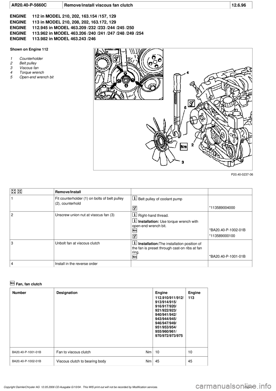
Shown on Engine 112
1
Counterholder
2
Belt pulley
3
Viscous fan
4
Torque wrench
5
Open-end wrench bit
Remove/Install
1
Fit counterholder (1) on bolts of belt pulley
(2), counterhold
Belt pulley of coolant pump
*113589004000
2
Unscrew union nut at visocus fan (3)
Right-hand thread.
Installation:
Use torque wrench with
open-end wrench bit.
*BA20.40-P-1002-01B
*113589000100
3
Unbolt fan at viscous clutch
Installation:
The installation position of
the fan is preset through cast-on ribs at fan
ring.
*BA20.40-P-1001-01B
4
Install in the reverse order
Fan, fan clutch
Number
Designation
Engine
112.910/911/912/
913/914/915/
916/917/920/
921/922/923/
940/941/942/
943/944/945/
946/947/949/
951/953/954/
955/960/961/
970/972/973/975
Engine
113
BA20.40-P-1001-01B
Fan to viscous clutch
Nm
1010
BA20.40-P-1002-01B
Viscous clutch to bearing body
Nm
4545
Copyright DaimlerChrysler AG 12.05.2006 CD-Ausgabe G/10/04 . This WIS print-out will not be recorde
d by Modification services.
Page 1
Page 4001 of 4133
Fig. 1: Manual A/C Circuit, W/ Coolant Fan Control Module (1 of 2)
2001 Mercedes-Benz ML320
2001 SYSTEM WIRING DIAGRAMS Mercedes-Benz - ML320
me
Saturday, October 02, 2010 3:27:58 PMPage 3 © 2006 Mitchell Repair Information Company, LLC.
Page 4003 of 4133
Fig. 2: Manual A/C Circuit, W/ Coolant Fan Control Module (2 of 2)
2001 Mercedes-Benz ML320
2001 SYSTEM WIRING DIAGRAMS Mercedes-Benz - ML320
me
Saturday, October 02, 2010 3:27:58 PMPage 5 © 2006 Mitchell Repair Information Company, LLC.
Page 4005 of 4133
Fig. 3: Manual A/C Circuit, W/O Coolant Fan Control Module (1 of 2)
2001 Mercedes-Benz ML320
2001 SYSTEM WIRING DIAGRAMS Mercedes-Benz - ML320
me
Saturday, October 02, 2010 3:27:58 PMPage 7 © 2006 Mitchell Repair Information Company, LLC.
Page 4007 of 4133
Fig. 4: Manual A/C Circuit, W/O Coolant Fan Control Module (2 of 2)
ANTI-LOCK BRAKES
2001 Mercedes-Benz ML320
2001 SYSTEM WIRING DIAGRAMS Mercedes-Benz - ML320
me
Saturday, October 02, 2010 3:27:58 PMPage 9 © 2006 Mitchell Repair Information Company, LLC.


