instrument panel MERCEDES-BENZ ML320 1997 Complete Owner's Manual
[x] Cancel search | Manufacturer: MERCEDES-BENZ, Model Year: 1997, Model line: ML320, Model: MERCEDES-BENZ ML320 1997Pages: 4133, PDF Size: 88.89 MB
Page 281 of 4133
231 Engine compartment
Te ch n ica l
data Instruments
and controlsOperation DrivingInstrument
cluster displayPractical hintsCar care Index Hood
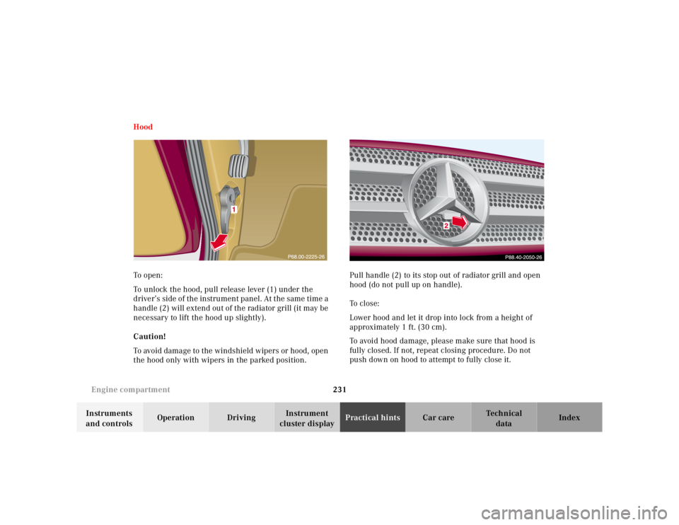
To o pen :
To unlock the hood, pull release lever (1) under the
driver’s side of the instrument panel. At the same time a
handle (2) will extend out of the radiator grill (it may be
necessary to lift the hood up slightly).
Caution!
To avoid damage to the windshield wipers or hood, open
the hood only with wipers in the parked position.Pull handle (2) to its stop out of radiator grill and open
hood (do not pull up on handle).
To c l o s e :
Lower hood and let it drop into lock from a height of
approximately 1 ft. (30 cm).
To avoid hood damage, please make sure that hood is
fully closed. If not, repeat closing procedure. Do not
push down on hood to attempt to fully close it.
Page 288 of 4133
238 Spare wheel, vehicle jack
Te ch n ica l
data Instruments
and controlsOperation DrivingInstrument
cluster displayPractical hintsCar care Index
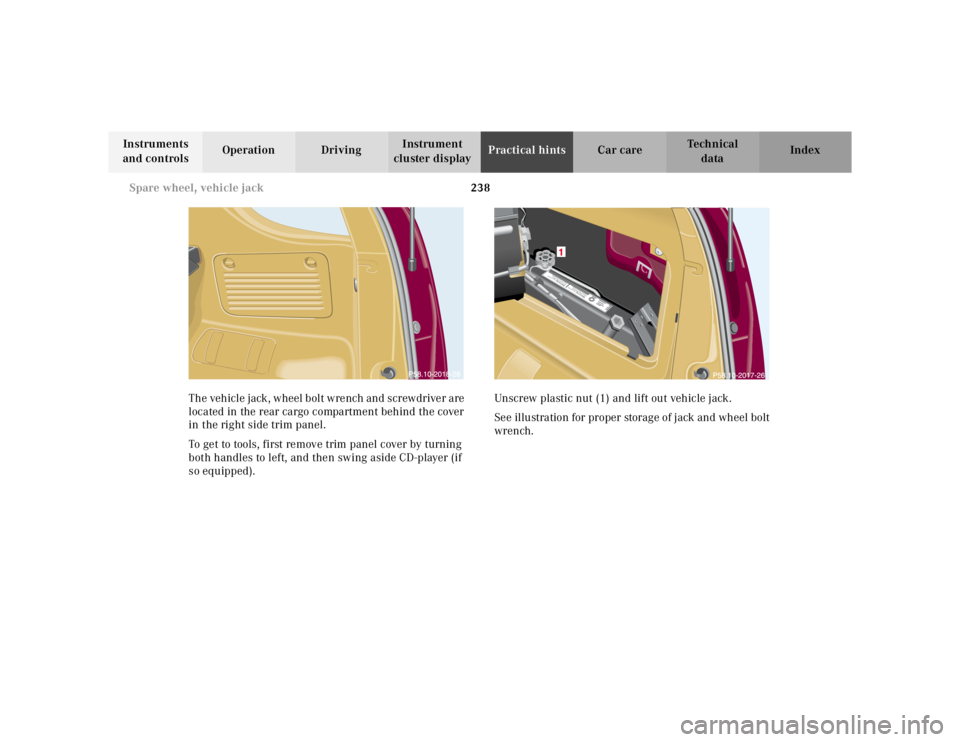
The vehicle jack, wheel bolt wrench and screwdriver are
located in the rear cargo compartment behind the cover
in the right side trim panel.
To get to tools, first remove trim panel cover by turning
both handles to left, and then swing aside CD-player (if
so equipped).Unscrew plastic nut (1) and lift out vehicle jack.
See illustration for proper storage of jack and wheel bolt
wrench.
Warnung!Sich nicht unter
das nur mit dem W
agenheber
aufgebockte Fahrzeug begeben!Warnung!Sich nicht unter
das nur mit dem W
agenheber
aufgebockte Fahrzeug begeben!
Page 298 of 4133
248 Tires, Wheels
Te ch n ica l
data Instruments
and controlsOperation DrivingInstrument
cluster displayPractical hintsCar care Index
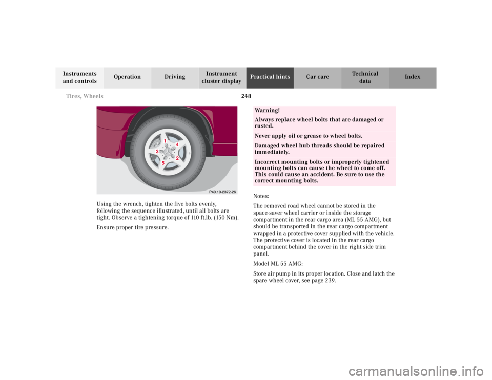
Using the wrench, tighten the five bolts evenly,
following the sequence illustrated, until all bolts are
tight. Observe a tightening torque of 110 ft.lb. (150 Nm).
Ensure proper tire pressure.Notes:
The removed road wheel cannot be stored in the
space-saver wheel carrier or inside the storage
compartment in the rear cargo area (ML 55 AMG), but
should be transported in the rear cargo compartment
wrapped in a protective cover supplied with the vehicle.
The protective cover is located in the rear cargo
compartment behind the cover in the right side trim
panel.
Model ML 55 AMG:
Store air pump in its proper location. Close and latch the
spare wheel cover, see page 239.
1
2
3
4
5
Wa r n i n g !
Always replace wheel bolts that are damaged or
rusted.Never apply oil or grease to wheel bolts.Damaged wheel hub threads should be repaired
immediately.Incorrect mounting bolts or improperly tightened
mounting bolts can cause the wheel to come off.
This could cause an accident. Be sure to use the
correct mounting bolts.
Page 306 of 4133
256 Towing
Te ch n ica l
data Instruments
and controlsOperation DrivingInstrument
cluster displayPractical hintsCar care Index
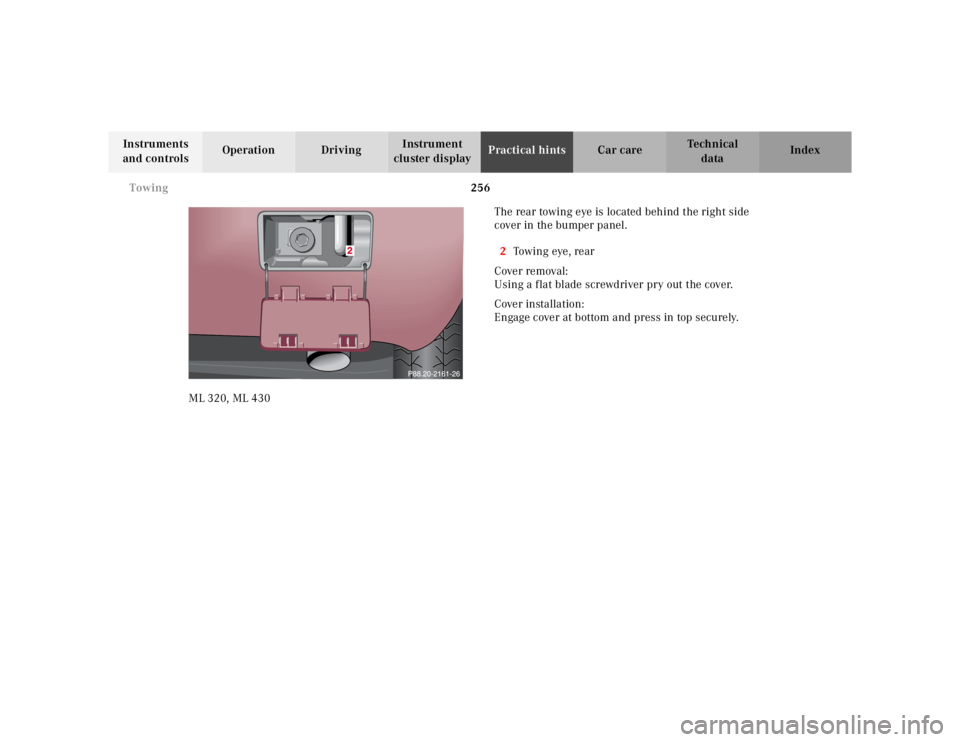
ML 320, ML 430The rear towing eye is located behind the right side
cover in the bumper panel.
2To w i n g eye , r e a r
Cover removal:
Using a flat blade screwdriver pry out the cover.
Cover installation:
Engage cover at bottom and press in top securely.
Page 307 of 4133
257 Towing
Te ch n ica l
data Instruments
and controlsOperation DrivingInstrument
cluster displayPractical hintsCar care Index ML 55 AMG
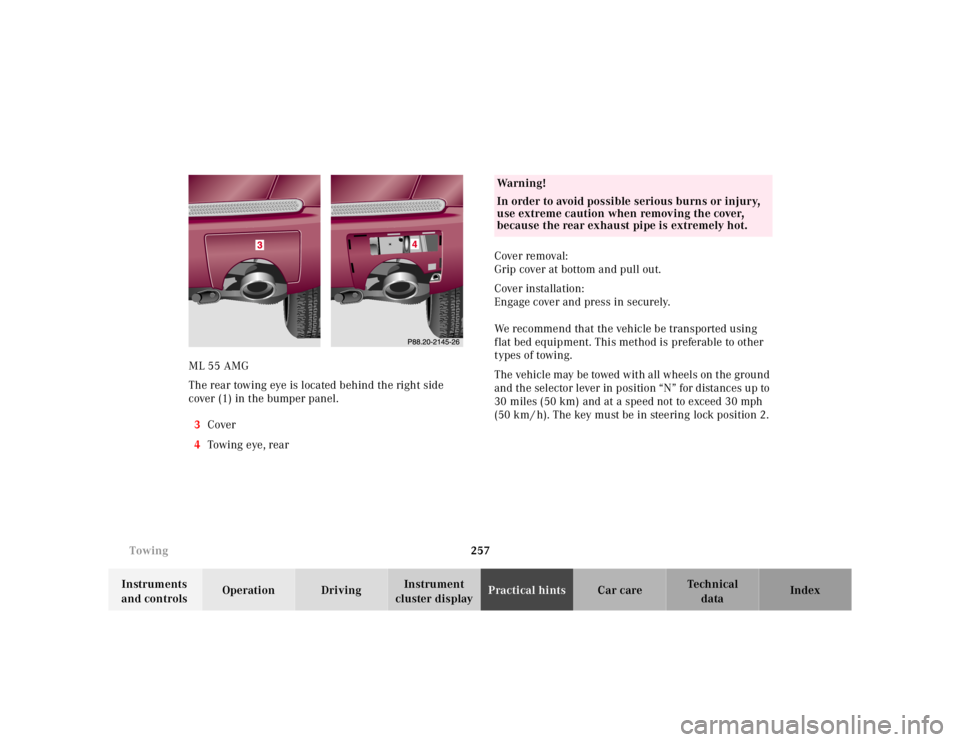
The rear towing eye is located behind the right side
cover (1) in the bumper panel.
3Cover
4Towing eye, rearCover removal:
Grip cover at bottom and pull out.
Cover installation:
Engage cover and press in securely.
We recommend that the vehicle be transported using
flat bed equipment. This method is preferable to other
types of towing.
The vehicle may be towed with all wheels on the ground
and the selector lever in position “N” for distances up to
30 miles (50 km) and at a speed not to exceed 30 mph
(50 k m / h). The key mu st be in stee ring lo ck p o sitio n 2.
Wa r n i n g !
In order to avoid possible serious burns or injury,
use extreme caution when removing the cover,
because the rear exhaust pipe is extremely hot.
Page 316 of 4133
266 Exterior lamps
Te ch n ica l
data Instruments
and controlsOperation DrivingInstrument
cluster displayPractical hintsCar care Index
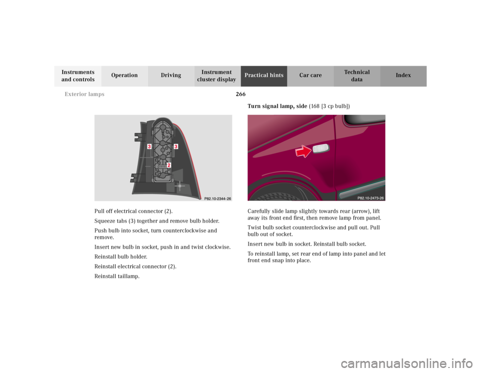
Pull off electrical connector (2).
Squeeze tabs (3) together and remove bulb holder.
Push bulb into socket, turn counterclockwise and
remove.
Insert new bulb in socket, push in and twist clockwise.
Reinstall bulb holder.
Reinstall electrical connector (2).
Reinstall taillamp.Turn signal lamp, side (168 [3 cp bulb])
Carefully slide lamp slightly towards rear (arrow), lift
away its front end first, then remove lamp from panel.
Twist bulb socket counterclockwise and pull out. Pull
bulb out of socket.
Insert new bulb in socket. Reinstall bulb socket.
To reinstall lamp, set rear end of lamp into panel and let
front end snap into place.
Page 324 of 4133
274 Manual release for fuel filler flap
Te ch n ica l
data Instruments
and controlsOperation DrivingInstrument
cluster displayPractical hintsCar care Index
Important!
After manually operating the Skyview Top, a timing
synchronization is needed for future electrical operation
o f the Sk yv iew To p. To do s o, tur n key i n stee ri n g lock to
position 2. Now push and hold switch until the Skyview
Top is fully closed. Continue to hold switch for
additional 15 seconds.Manual release for fuel filler flap
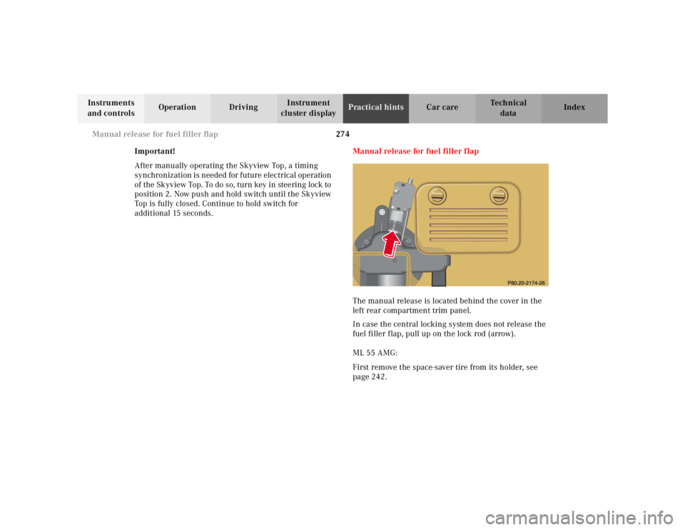
The manual release is located behind the cover in the
left rear compartment trim panel.
In case the central locking system does not release the
fuel filler flap, pull up on the lock rod (arrow).
ML 55 AMG:
First remove the space-saver tire from its holder, see
page 242.
Page 352 of 4133
302 Index
Te ch n ica l
data Instruments
and controlsOperation DrivingInstrument
cluster displayPractical hints Car careIndex
Clock, adjusting ............................................................... 80
Compartment under front passenger seat ..................116
Consumer information ..................................................298
Control and operation of radio transmitters ............. 146
Coolant level
Adding ........................................................................235
Checking ....................................................................234
Low engine coolant level warning ..........................224
Coolant temperature gauge ............................................ 81
Coolants ...........................................................................296
Anticorrosion/antifreeze quantity .........................296
Low engine coolant level warning ..........................224
Cover blind, cargo area ................................................. 137
Cruise control ................................................................. 196
Cup holder
Instrument panel .......................................................116
Rear center console ...................................................117
DDaytime running lamps .................................................. 91
Deep water
Driving instructions ................................................. 181
Defroster, rear window .................................................. 103
Display illumination ........................................................ 80Doors .................................................................................. 30
Drinking and driving ..................................................... 174
Drive sensibly - save fuel .............................................. 174
Driving instructions ...................................................... 174
Driving off ....................................................................... 176
EEBP (Electronic brake proportioning) ........................ 204
Electrical outlet ............................................................. 230
Electronic brake proportioning (EBP) ........................ 204
Electronic stability program (ESP) ............................. 205
Control switch .......................................................... 207
Malfunction indicator lamp .....................................221
Synchronizing .......................................................... 206
Warning lamp ............................................................221
Electronic traction system (4-ETS+) ........................... 203
LOW RANGE – 4-ETS ............................................... 204
Malfunction indicator lamp .....................................221
Emergency call
See Tele Aid ...............................................................148
Emergency operation of Skyview Top ....................... 273
Emergency tensioning retractor (ETR) .........................55
Emergency unlocking in case of accident ...................33
Emission control ............................................................ 161
Page 357 of 4133
307 Index
Te ch n ica l
data Instruments
and controlsOperation DrivingInstrument
cluster displayPractical hints Car careIndex
OObtaining replacement keys .......................................... 25
Odometer/Trip odometer ................................................ 80
Off-Road driving ............................................................. 183
On-board diagnostic system ......................................... 218
Operator’s manual ............................................................. 8
Outside temperature indicator ...................................... 82
Overhead control panel ................................................... 21PPanic button ...................................................................... 28
Parking .............................................................................176
Parking brake ....................... 118, 173, 175, 176, 219, 245
Partition net .................................................................... 133
Poly-V-belt
Layout .........................................................................286
Power assistance ............................................................ 175
Power seats, front ............................................................ 40
Memory ........................................................................ 42
Memory recalling ....................................................... 42
Memory storing ........................................................... 42Power windows ...............................................................104
Blocking of rear door windows ............................... 105
Express opening of front door windows ................ 105
Problems with your vehicle ............................................ 15
Product information .......................................................... 7
RRadio transmitters ......................................................... 146
Rain sensor
See windshield wiper/washer switch ......................95
Rear quarter windows ...................................................106
Rear seat bench ..............................................................120
Easy entry/exit feature ............................................123
Head restraints ..........................................................124
Rear seat head restraints ..............................................124
Adjusting ....................................................................125
Removal ......................................................................125
Rear view mirrors
Exterior ......................................................................... 73
Inside ............................................................................ 71
Rear window defroster .................................................. 103
Rear window wiper/washer ...........................................96
Page 377 of 4133
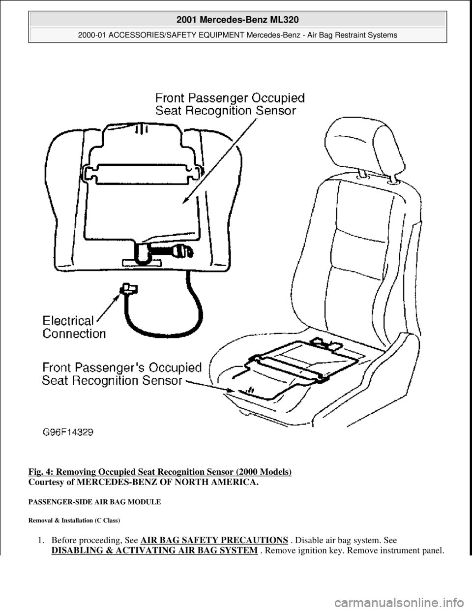
Fig. 4: Removing Occupied Seat Recognition Sensor (2000 Models)
Courtesy of MERCEDES-BENZ OF NORTH AMERICA.
PASSENGER-SIDE AIR BAG MODULE
Removal & Installation (C Class)
1. Before proceeding, See AIR BAG SAFETY PRECAUTIONS . Disable air bag system. See
DISABLING & ACTIVATI NG AIR BAG SYSTEM
. Remove ignition key. Remove instrument panel.
2001 Mercedes-Benz ML320
2000-01 ACCESSORIES/SAFETY EQUIPMENT Merc edes-Benz - Air Bag Restraint Systems
me
Saturday, October 02, 2010 3:44:45 PMPage 13 © 2006 Mitchell Repair Information Company, LLC.