seat memory MERCEDES-BENZ ML320 1997 Complete Owner's Manual
[x] Cancel search | Manufacturer: MERCEDES-BENZ, Model Year: 1997, Model line: ML320, Model: MERCEDES-BENZ ML320 1997Pages: 4133, PDF Size: 88.89 MB
Page 1136 of 4133

332 IndexPartition net* 159
Engaging 159
Removing 161
Tightening 160
Parts see Spare parts service
Passenger compartment 211
Interior lighting 112
Passenger footwell
Fuse box in 288
Passenger safety see Occupant
safety 58
Pedals 193
Plastic and rubber parts
Cleaning 239
Poly-V-belt drive 314
Layout 293
Positions (Memory function*)
Recalling from memory 106
Storing into memory 106
Power assistance 193Power seat*
Adjusting backrest tilt 38
Adjusting head restraint height 38
Adjusting seat cushion tilt 38
Adjusting seat height 38
Seat fore and aft adjustment 37
Power seats* 37
Power train 314
Power washer 235
Power windows
Blocking of rear door window
operation 73
Side windows 144
Synchronizing 146
Practical hints
First aid kit 257
Fuses 287
Lamps in instrument cluster 242
Spare wheel 259
Towing the vehicle 283
Vehicle jack 258
Vehicle tool kit 257Premium unleaded gasoline 303
Problems
While driving 51
With vehicle 18
Product information 9
Programming or reprogramming the inte-
grated remote control 182
R
Radio transmitters, control and
operation 211
Rain sensor* 130, 131
Rapid seat heating
Switching off 99
Rapid seat heating*
Switching on 98
Reading lamp 29
Page 1140 of 4133

336 IndexSide windows 144
Automatic closing 145
Automatic opening 145
Cleaning 237
Closing 145
Closing fully (Express-close) 145
Opening 145
Opening and closing 144
Opening fully (Express-open) 145
Rear quarter window 146
Stopping 145
Synchronizing power windows 146
Simultaneous wiping and washing
Rear window wiper/washer 51
Windshield wipers 50
Single wipe 50
Sliding/pop-up roof* 148
Closing 148, 265
Opening 148, 265
Synchronizing 149
Snow chains 231
Spare fuses 287
Spare parts service 290Spare wheel 259
Mounting 274
Removing 259
Speed
Saving current 151
Speed settings
Cruise control 152
Speedometer 25
Speedometer display
Additional indicators 256
Split rear bench seat 99
SRS 66, 314
Indicator lamp 255
Standing lamps 107
Replacing bulbs 266, 267
Standing water
Driving instructions 200
StArt
Display messages 256
Starting difficulties 47
Starting position 33
Starting the engine 46Steep terrain
Driving 202
Steering column
Height adjustment 39
Length adjustment 39
Steering lock 23, 33
Positions 33
Steering wheel
Adjusting 39
Adjustment 39
Cleaning 238
Stolen vehicle
Tracking services 180
Stop watch 189
Stopping
Windows 145
Storage compartments
Glove box 164
Under front passenger seat* 164
Storing (Memory function*)
Positions into memory 106
Stranded vehicle 286
Page 2042 of 4133
3. Normalize side power windows. See NORMALIZING POWER WINDOWS .
4. Start engine and run at idle. Turn steering wheel from one lock position to the other to activate steering
angle sensor. Center steering wheel. Message "EI. STAB. PROGRAM GO TO GARAGE" should erase
from multifunction display panel.
5. If equipped, normalize tilting/sliding roof. See NORMALIZING TILTING/SLIDING ROOF
.
6. If equipped, normalize memory power seats, steering column and outside mirror if components are
installed. See NORMALIZING MEMORY POWER SEATS, STEERING COLUMN & OUTSIDE
MIRROR .
Normalizing Power Windows
1. Completely close each window with manual switch. Hold switch in closed position for .3 second.
2. Repeat procedure for each power window.
Normalizing Memory Power Seats, Steering Column & Outside Mirror
1. Using manual switch, move seat to each end position and hold for .3 second. Repeat procedure for each
switch except rear stop of backrest.
2. Repeat procedure for end positions of steering wheel and outside mirrors.
Normalizing Tilting/Sliding Roof
Open roof with SR switch until mechanical stop is reached. Continue to press switch for .5 seconds.
Setting Time
1. Use bottom left button on steering wheel to scroll through menus on instrument cluster to "Settings"
menu.
2. Move selection marker with + or - button to "Time" submenu.
3. Press up or down arrows to "Clock, hours" setting. Confirm selection marker is on the hour setting.
4. Press + or - to set hour. Press reset knob in instrument cluster to confirm.
5. Move selection marker with + or - button to "Time" submenu.
6. Press up or down arrows to "Clock, minutes" setting. Confirm selection marker is on the minutes setting.
7. Press + or - to set minute. Press reset knob in instrument cluster to confirm.
TESTING
If generator malfunctions, check for Diagnostic Trouble Codes (DTCs) in Motor Electronics Sequential Fuel
Injection (ME-SFI) system. See appropriate SELF-DIAGNOSTICS article in ENGINE PERFORMANCE. If
cause of generator malfunction is not engine performance related, replace generator.
RETRIEVING & ERASING DIAGNOSTIC TROUBLE CODES
NOTE: Before replacing any component that scan tool suggests are faulty, ensure that
all wiring connections and harness connectors are okay. Ensure that power and
2001 Mercedes-Benz ML320
2001-04 STARTING & CHARGING SYSTEMS Generators & Regulators - 163 Chassis
me
Saturday, October 02, 2010 3:20:32 PMPage 8 © 2006 Mitchell Repair Information Company, LLC.
Page 2067 of 4133

GF72.29-P-2002GH
Convenience control, function
7.4.97
MODEL
163
The convenience control allows the driver to operate the electrical
seat adjustment, the power windows, the electric vent windows, the
electric outside rearview mirror as well as the electric sliding/pop-up
roof or the electric lamella sliding roof
when the ignition is switched
off.
To achieve this, the all-activity module (AAM) (N10) switches to the
corresponding loads via the convenience relay (F1k14)
circuit 30 .
As of 12.99 the vehicle is equipped with its own convenience relay for
seat adjustment (relay 1, F2k1). In addition the status of the
convenience control via CAN is transmitted to the extended activity
module (EAM, N10/1).
Conditions for control actuation
On all-activity module (AAM) (N10) configured for
I
up
to
11.99:
The convenience actuation becomes active as soon as
D
Circuit 15 ON is recognized
When circuit 15 is switched off, the convenience actuation is
deactivated after a door is opened
Otherwise
The convenience actuation is active in the following cases:
D
Circuit 15c ON
D
A front door is open
D
The remote control key is removed, however, the doors are not
yet opened
In both cases the convenience actuation remains active for 5 min.
Switch-on condition for circuit 15c
When the remote control key is inserted into the ignition lock, circuit
15c is switched on when the key is turned out of the zero position.
Circuit 15c switches off only after the remote control key is removed
from the ignition lock
Electric seat adjustment without memory,
function
GF91.29-P-0003GH
Electric seat adjustment with memory, function
as of 12.99
GF91.29-P-0002GH
Convenience control, function
for electrical seat adjustment as of 12.99
GF91.29-P-2013GK
Power windows, function
GF72.29-P-0003GH
Power tilting/sliding roof (SR), function
GF77.20-P-0001GH
Electrically adjustable outside rearview
mirrors, function
GF88.79-P-0005GH
Electric vent windows, function
GF67.39-P-1000GH
Extended activity module,
location/purpose/design
as of 12.99
GF54.21-P-4107GK
Copyright DaimlerChrysler AG 04.08.2006 CD-Ausgabe G/10/04 . This WIS print-out will not be recorde
d by Modification services.
Page 1
Page 3499 of 4133
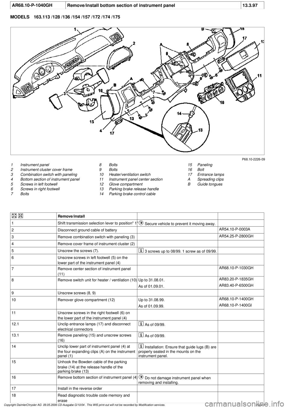
AR68.10-P-1040GH
Remove/install bottom section of instrument panel
13.3.97
MODELS
163.113 /128 /136 /154 /157 /172 /174 /175
P68.10-2226-09
1
Instrument panel
2
Instrument cluster cover frame
3
Combination switch with paneling
4
Bottom section of instrument panel
5
Screws in left footwell
6
Screws in right footwell
7
Bolts
15
Paneling
16
Bolt
17
Entrance lamps
A
Spreading clips
B
Guide tongues
8
Bolts
9
Bolts
10
Heater/ventilation switch
11
Instrument panel center section
12
Glove compartment
13
Parking brake release handle
14
Parking brake control cable
Remove/install
1
Shift transmission selection lever to position" 1"
Secure vehicle to prevent it moving away.
2
Disconnect ground cable of battery
AR54.10-P-0003A
3
Remove combination switch with paneling (3)
AR54.25-P-2800GH
4
Remove cover frame of instrument cluster (2)
5
Unscrew the screws (7).
3 screws up to 08/99. 1 screw as of 09/99.
6
Unscrew screws in left footwell (5) on the
lower part of the instrument panel (4)
7
Remove center section of instrument panel
(11)
AR68.10-P-1030GH
8
Remove switch unit for heater / ventilation (10)
Up to 31.08.01.
AR83.20-P-1835GH
As of 01.09.01.
AR83.40-P-6500GH
9
Unscrew screws (8, 9)
10
Remover glove compartment (12)
Up to 31.08.99.
AR68.10-P-1400GH
As of 01.09.99.
AR68.10-P-1400GI
11
Unscrew screws in the right footwell (6) on
the lower part of the instrument panel (4)
12.1
Unclip entrance lamps (17) and disconnect
electrical connectors
As of 09/99.
13.1
Remove paneling (15) and unscrew screws
(16)
As of 09/99.
14
Unclip lower part of instrument panel (4) at
the four expanding clips (A) on the instrument
panel (1)
Installation: Ensure that guide lugs (B) are
properly seated in the mounts on the
instrument panel.
15
Unhook the Bowden cable of the parking
brake (14) at the release handle of the
parking brake (13)
16
Remove bottom section of instrument panel (4)
Do not damage instrument panel when
removing and installing.
17
Install in the reverse order
18
Read diagnostic trouble code memory and
erase
Copyright DaimlerChrysler AG 09.05.2006 CD-Ausgabe G/10/04 . This WIS print-out will not be recorde
d by Modification services.
Page 1
Page 3539 of 4133
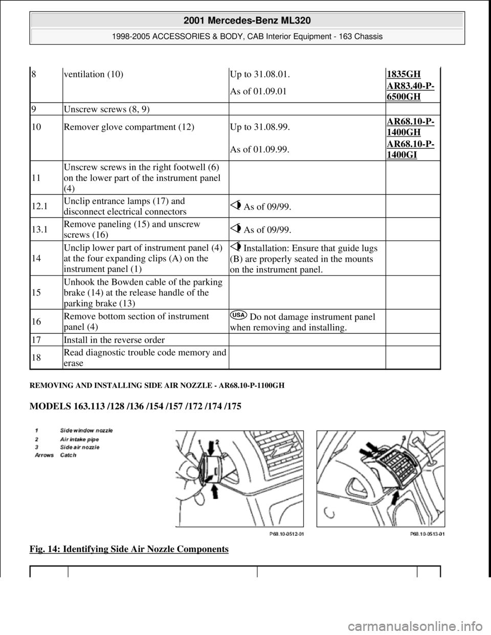
REMOVING AND INSTALLING SIDE AIR NOZZLE - AR68.10-P-1100GH
MODELS 163.113 /128 /136 /154 /157 /172 /174 /175
Fig. 14: Identifying Side Air Nozzle Components
8ventilation (10)Up to 31.08.01.1835GH
As of 01.09.01AR83.40-P-
6500GH
9Unscrew screws (8, 9)
10Remover glove compartment (12)Up to 31.08.99.AR68.10-P-
1400GH
As of 01.09.99.AR68.10-P-
1400GI
11
Unscrew screws in the right footwell (6)
on the lower part of the instrument panel
(4)
12.1Unclip entrance lamps (17) and
disconnect electrical connectors As of 09/99.
13.1Remove paneling (15) and unscrew
screws (16) As of 09/99.
14
Unclip lower part of instrument panel (4)
at the four expanding clips (A) on the
instrument panel (1) Installation: Ensure that guide lugs
(B) are properly seated in the mounts
on the instrument panel.
15
Unhook the Bowden cable of the parking
brake (14) at the release handle of the
parking brake (13)
16Remove bottom section of instrument
panel (4) Do not damage instrument panel
when removing and installing.
17Install in the reverse order
18Read diagnostic trouble code memory and
erase
2001 Mercedes-Benz ML320
1998-2005 ACCESSORIES & BODY, CAB Interior Equipment - 163 Chassis
me
Saturday, October 02, 2010 3:35:21 PMPage 21 © 2006 Mitchell Repair Information Company, LLC.
Page 3789 of 4133
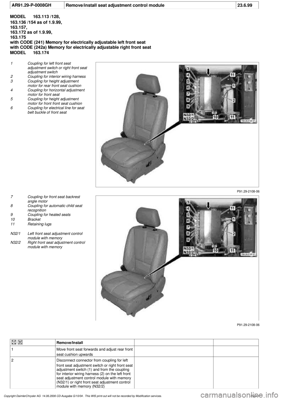
AR91.29-P-0008GH
Remove/install seat adjustment control module
23.6.99
MODEL
163.113 /128,
163.136 /154 as of 1.9.99,
163.157,
163.172 as of 1.9.99,
163.175
with CODE (241) Memory for electrically adjustable left front seat
with CODE (242a) Memory for electrically adjustable right front seat
MODEL
163.174
P91.29-2108-06
1
Coupling for left front seat
adjustment switch or right front seat
adjustment switch
2
Coupling for interior wiring harness
3
Coupling for height adjustment
motor for rear front seat cushion
4
Coupling for horizontal adjustment
motor for front seat
5
Coupling for height adjustment
motor for front front seat cushion
6
Coupling for electrical line for seat
belt buckle of front seat
P91.29-2108-06
7
Coupling for front seat backrest
angle motor
8
Coupling for automatic child seat
recognition
9
Coupling for heated seats
10
Bracket
11
Retaining lugs
N32/1
Left front seat adjustment control
module with memory
N32/2
Right front seat adjustment control
module with memory
Remove/Install
1
Move front seat forwards and adjust rear front
seat cushion upwards
2
Disconnect connector from coupling for left
front seat adjustment switch or right front seat
adjustment switch (1) and from the coupling
for interior wiring harness (2) on the left front
seat adjustment control module with memory
(N32/1) or right front seat adjustment control
module with memory (N32/2)
Copyright DaimlerChrysler AG 14.06.2006 CD-Ausgabe G/10/04 . This WIS print-out will not be recorde
d by Modification services.
Page 1
Page 3790 of 4133

3
Unscrew bolt (arrow) from bracket (10),
unhook front bracket and remove
4
Remove left front seat adjustment control
module with memory (N32/1) or right front
seat adjustment control module with memory
(N32/2) from bracket on front seat frame
Unhook two retaining lugs (11) on the side.
5
Disconnect the remaining connectors on the
left front seat adjustment control module with
memory (N32/1) or right front seat adjustment
control module with memory (N32/2)
6
Remove left front seat adjustment control
module with memory (N32/1) or right front
seat adjustment control module with memory
(N32/2)
7
Install in the reverse order
8
Perform function check
Copyright DaimlerChrysler AG 14.06.2006 CD-Ausgabe G/10/04 . This WIS print-out will not be recorde
d by Modification services.
Page 2
Page 3791 of 4133
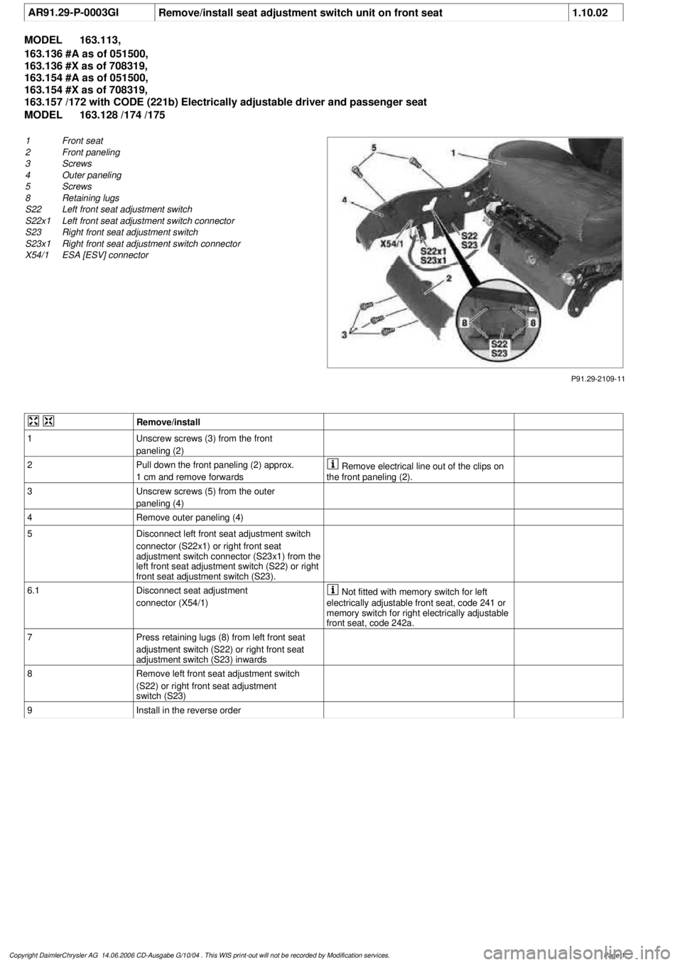
AR91.29-P-0003GI
Remove/install seat adjustment switch unit on front seat
1.10.02
MODEL
163.113,
163.136 #A as of 051500,
163.136 #X as of 708319,
163.154 #A as of 051500,
163.154 #X as of 708319,
163.157 /172 with CODE (221b) Electrically adjustable driver and passenger seat
MODEL
163.128 /174 /175
P91.29-2109-11
1
Front seat
2
Front paneling
3
Screws
4
Outer paneling
5
Screws
8
Retaining lugs
S22
Left front seat adjustment switch
S22x1
Left front seat adjustment switch connector
S23
Right front seat adjustment switch
S23x1
Right front seat adjustment switch connector
X54/1
ESA [ESV] connector
Remove/install
1
Unscrew screws (3) from the front
paneling (2)
2
Pull down the front paneling (2) approx.
1 cm and remove forwards
Remove electrical line out of the clips on
the front paneling (2).
3
Unscrew screws (5) from the outer
paneling (4)
4
Remove outer paneling (4)
5
Disconnect left front seat adjustment switch
connector (S22x1) or right front seat
adjustment switch connector (S23x1) from the
left front seat adjustment switch (S22) or right
front seat adjustment switch (S23).
6.1
Disconnect seat adjustment
connector (X54/1)
Not fitted with memory switch for left
electrically adjustable front seat, code 241 or
memory switch for right electrically adjustable
front seat, code 242a.
7
Press retaining lugs (8) from left front seat
adjustment switch (S22) or right front seat
adjustment switch (S23) inwards
8
Remove left front seat adjustment switch
(S22) or right front seat adjustment
switch (S23)
9
Install in the reverse order
Copyright DaimlerChrysler AG 14.06.2006 CD-Ausgabe G/10/04 . This WIS print-out will not be recorde
d by Modification services.
Page 1
Page 3792 of 4133
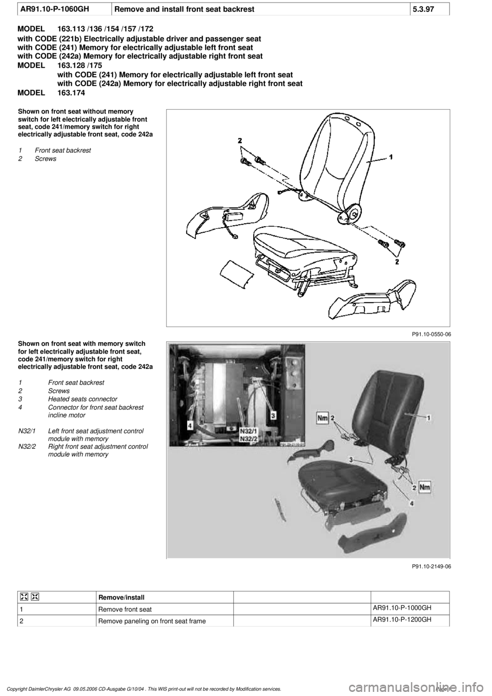
AR91.10-P-1060GH
Remove and install front seat backrest
5.3.97
MODEL
163.113 /136 /154 /157 /172
with CODE (221b) Electrically adjustable driver and passenger seat
with CODE (241) Memory for electrically adjustable left front seat
with CODE (242a) Memory for electrically adjustable right front seat
MODEL
163.128 /175
with CODE (241) Memory for electrically adjustable left front seat
with CODE (242a) Memory for electrically adjustable right front seat
MODEL
163.174
P91.10-0550-06
Shown on front seat without memory
switch for left electrically adjustable front
seat, code 241/memory switch for right
electrically adjustable front seat, code 242a
1
Front seat backrest
2
Screws
P91.10-2149-06
Shown on front seat with memory switch
for left electrically adjustable front seat,
code 241/memory switch for right
electrically adjustable front seat, code 242a
1
Front seat backrest
2
Screws
3
Heated seats connector
4
Connector for front seat backrest
incline motor
N32/1
Left front seat adjustment control
module with memory
N32/2
Right front seat adjustment control
module with memory
Remove/install
1
Remove front seat
AR91.10-P-1000GH
2
Remove paneling on front seat frame
AR91.10-P-1200GH
Copyright DaimlerChrysler AG 09.05.2006 CD-Ausgabe G/10/04 . This WIS print-out will not be recorde
d by Modification services.
Page 1