air condition MERCEDES-BENZ ML320 1997 Complete Repair Manual
[x] Cancel search | Manufacturer: MERCEDES-BENZ, Model Year: 1997, Model line: ML320, Model: MERCEDES-BENZ ML320 1997Pages: 4133, PDF Size: 88.89 MB
Page 3857 of 4133
different engine loads, e.g. power steering turned to full lock, engaging drive mode, switching on AC
compressor
different mixture, e.g. from activated charcoal canister if purging activated (depending on activated
charcoal charge)
Function
The actuator EFP/TPM/LLR (additional designation: throttle valve actuator) regulates the idling speed by
changing the throttle valve position. It is actuated by the ME-SFI control unit.
The ME-SFI control unit actuates the throttle valve motor (M16/1 m1) in line with the input signals received at
the ME-SFI control unit (N3/10).
Heating speed of the catalytic converter
In order to warm up the catalytic converter more rapidly to operating temperature, engine speed is increased in
the idle speed range to 1100 up to 1500 rpm for about 20 seconds after each starting procedure at coolant
temperatures of < 40 °C. When a Drive position is engaged, engine speed is immediately controlled to a lower
value.
Automatic transmission
When a drive position is engaged, a lower engine speed is controlled in order to reduce the creeping tendency o
f
the vehicle. The information "Drive position engaged/not engaged" is transmitted by the ETC control unit
(N15/3) over the CAN databus to the ME-SFI control unit.
Ignition angle
To assist the idle speed control, the ignition angle can be retarded by as much as 36° crank angle or advanced by
as much as 20° crank angle from the calculated specified value.
The control in the idle speed range by altering the ignition angle reacts more rapidly than altering the position o
f
the throttle valve.
The idling speed can be influenced with HHT or the STAR DIAGNOSIS.
AC compressor
In order to avoid engine speed dropping in the idle speed range when the AC compressor is engaged, the AC
push-button control unit (N19) or automatic air conditioning push-button control unit (N22) supplies a signal to
the ME-SFI control unit (as of approx. 6/96 over CAN) and the opening cross-section of the throttle valve is
enlarged.
When the air conditionin
g unit is switched on and the external temperature exceeds 35° C the idling speed on
2001 Mercedes-Benz ML320
1998-2005 ACCESSORIES & BODY CAB Throttle Control, Speed Control Systems - 163 Chassis
me
Saturday, October 02, 2010 3:36:27 PMPage 17 © 2006 Mitchell Repair Information Company, LLC.
Page 3861 of 4133
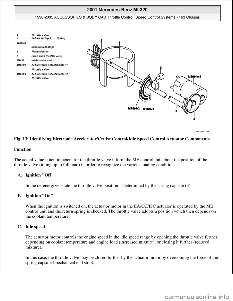
Fig. 13: Identifying Electronic Accelerator/Cruise Control/Idle Speed Control Actuator Components
Function
The actual value potentiometers for the throttle valve inform the ME control unit about the position of the
throttle valve (idling up to full load) in order to recognize the various loading conditions.
A.Ignition "Off"
In the de-energized state the throttle valve position is determined by the spring capsule (3).
B.Ignition "On"
When the ignition is switched on, the actuator motor in the EA/CC/ISC actuator is operated by the ME
control unit and the return spring is checked. The throttle valve adopts a position which then depends on
the coolant temperature.
C.Idle speed
The actuator motor controls the engine speed in the idle speed range by opening the throttle valve further,
depending on coolant temperature and engine load (increased mixture), or closing it further (reduced
mixture).
In this case, the throttle valve may be closed further by the actuator motor by overcoming the force of the
sprin
g capsule (mechanical end stop).
2001 Mercedes-Benz ML320
1998-2005 ACCESSORIES & BODY CAB Throttle Control, Speed Control Systems - 163 Chassis
me
Saturday, October 02, 2010 3:36:27 PMPage 21 © 2006 Mitchell Repair Information Company, LLC.
Page 3862 of 4133
If the actuator is de-energized, the throttle valve is resting against the spring capsule. As a result the
throttle valve opening is constantly approx. 10 to 12 °. The engine speed for the no load condition is
about 1800 rpm.
D.Driving mode
The actuating motor when driving (partial/full load) regulates the throttle valve according to the various
loading conditions or according to the input signals from the front pedal value sensor (B37) according to
the position of the accelerator pedal.
E.Throttle valve damping
A damping function for the throttle valve is integrated in the ME control unit. In case of a sudden release of the
accelerator, the throttle valve in the idle speed range is closed with delay.
When first connecting to terminal 30 the ME control unit independently undertakes adaptation of the actuator
(learn the lower mechanical limit stop and full-load position of the throttle valve).
ELECTRONIC ACCELERATOR/CRUISE CONTROL/IDLE SPEED CONTROL ACTUATOR
LOCATION/TASK/DESIGN/FUNCTION - GF30.22-P-4010F
ENGINE 104.941 /943 /944 /991 /994 as of 1/8/96
ENGINE 104.995
with CODE (494a) USA version
with CODE (807) Model year 1997
with CODE (808) Model year 1998
with CODE (498) as of Model year 97 Japanese version
ENGINE 111.921 /942 as of 1.9.98,
111.943,
111.944 as of 1.8.96,
111.946 as of 1.6.98,
111.947/973,
111.975 as of 1.8.96
2001 Mercedes-Benz ML320
1998-2005 ACCESSORIES & BODY CAB Throttle Control, Speed Control Systems - 163 Chassis
me
Saturday, October 02, 2010 3:36:27 PMPage 22 © 2006 Mitchell Repair Information Company, LLC.
Page 3864 of 4133
CRUISE CONTROL (CC) FUNCTION - GF30.30-P-0001FA
ENGINE 112.923 /943, 113.961, 120.983 in MODEL 129
ENGINE 112.942 /970, 113.942 /965 in MODEL 163
ENGINE 111.943 /946 /958 /973 /983, 112.947 in MODEL 170
ENGINE 111.921 /944 /945 as of 1.8.99,
111.952/956/974,
111.975 as of 1.8.99,
112.910/920,113.944
Electronic accelerator/cruise
control/idle speed control actuator
position
Engine 104GF30.22-P-
4010-01D
Engine 111GF30.22-P-
4010-01G
Engine 112, 113GF30.22-P-
4010-01A
Engine 119GF30.22-P-
4010-01E
Engine 120GF30.22-P-
4010-01F
Engine 137GF30.22-P-
4010-01L
Electronic accelerator/cruise
control/idle speed control actuator
task
Determining the opening angle of the throttle valve
in accordance with the operating condition:
Controlling idle speed under different engine
loads (power steering turned to full lock, AC
compressor engaged)
Cruise control mode
Emergency electronic accelerator pedal
Driving, in accordance with accelerator pedal
position.
Electronic accelerator/cruise
control/idle speed control actuator
task
GF30.22-P-
4010-02F
Electronic accelerator/cruise
control/idle speed control actuator
function
GF30.22-P-
4010-03F
2001 Mercedes-Benz ML320
1998-2005 ACCESSORIES & BODY CAB Throttle Control, Speed Control Systems - 163 Chassis
me
Saturday, October 02, 2010 3:36:27 PMPage 24 © 2006 Mitchell Repair Information Company, LLC.
Page 3872 of 4133
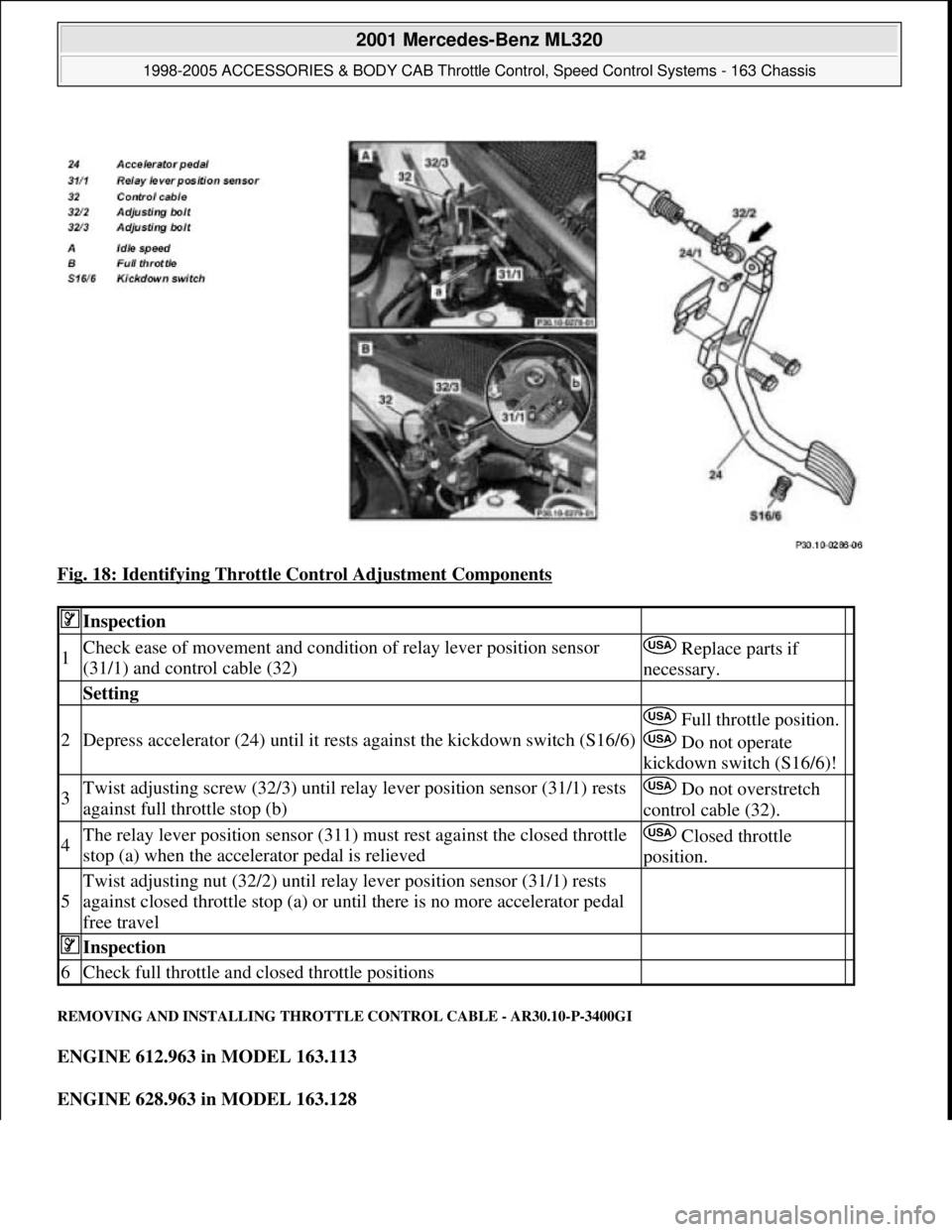
Fig. 18: Identifying Throttle Control Adjustment Components
REMOVING AND INSTALLING THROTTLE CONTROL CABLE - AR30.10-P-3400GI
ENGINE 612.963 in MODEL 163.113
ENGINE 628.963 in MODEL 163.128
Inspection
1Check ease of movement and condition of relay lever position sensor
(31/1) and control cable (32) Replace parts if
necessary.
Setting
2Depress accelerator (24) until it rests against the kickdown switch (S16/6)
Full throttle position.
Do not operate
kickdown switch (S16/6)!
3Twist adjusting screw (32/3) until relay lever position sensor (31/1) rests
against full throttle stop (b) Do not overstretch
control cable (32).
4The relay lever position sensor (311) must rest against the closed throttle
stop (a) when the accelerator pedal is relieved Closed throttle
position.
5
Twist adjusting nut (32/2) until relay lever position sensor (31/1) rests
against closed throttle stop (a) or until there is no more accelerator pedal
free travel
Inspection
6Check full throttle and closed throttle positions
2001 Mercedes-Benz ML320
1998-2005 ACCESSORIES & BODY CAB Throttle Control, Speed Control Systems - 163 Chassis
me
Saturday, October 02, 2010 3:36:28 PMPage 32 © 2006 Mitchell Repair Information Company, LLC.
Page 3883 of 4133
2001-04 STARTING & CHARGING SYSTEMS Starters - 163 Chassis
MODEL IDENTIFICATION
MODEL IDENTIFICATION
DESCRIPTION
Starter is a brush-type, series-wound el ectric motor with an overrunning clutch. Field frame contains field coils
and is enclosed by commutator/drive bushing end frame, which carries pole shoes. A splined armature shaft
carries drive assembly.
TROUBLE SHOOTING
BASIC TROUBLESHOOTING
If starter is noisy, the cause could be bent or damaged gear tooth chamfers on ring gear. This cannot be seen
with starter installed in ve hicle. Activate starter without switching ignition on. Me tallic noise should not be
heard. If noise is he ard, replace ring gear.
PRELIMINARY INSPECTION
Verify customer complaint by operating system. Visually inspect for obvious signs of mechanical and electrical
damage. Check generator belt tension and condition. Ensure that battery voltage is within specifications. Inspect
for blown fuses and damaged relays. For fuse and/or relay identification, see WIRING DIAGRAMS
.
WARNING:
Vehicles are equipped with air bag supplemental restraint system. Before
attempting any repairs involving steer ing column, instrument panel or
related components, see SERVICE PRECAUTIONS (or AIR BAG SAFETY
PRECAUTIONS) and DISABLING & ACTIVATING AIR BAG SYSTEM in
appropriate AIR BAG REST RAINT SYSTEMS article.
NOTE: When the battery is di sconnected, vehicle computer and memory system may
lose data. Driveability problems may exist until computer systems have
completed a relearn cycle. Radio will not operate until coded. Obtain code card
from customer.
NOTE: The following table identifies mo dels applicable to this article.
ModelChassisEngine Number
ML430 (2001)163.172113.942
ML320 (2001-03)163.154112.942
ML55 AMG (2001-03)163.174113.981
ML500 (2002-04)163.175113.965
ML350 (2003-04)163.157112.970
2001 Mercedes-Benz ML320
2001-04 STARTING & CHARGING SYSTEMS Starters - 163 Chassis
2001 Mercedes-Benz ML320
2001-04 STARTING & CHARGING SYSTEMS Starters - 163 Chassis
me
Saturday, October 02, 2010 3:19:47 PMPage 1 © 2006 Mitchell Repair Information Company, LLC.
me
Saturday, October 02, 2010 3:19:50 PMPage 1 © 2006 Mitchell Repair Information Company, LLC.
Page 3884 of 4133
Verify ground connection integrity between engine, body, battery and generator. Check for damaged wiring
harnesses and/or switches. Check fo r a broken or partially broken wire inside insulation, which could cause
system malfunction but prove good in a continuity/vol tage check with system disconnected. Ensure any
aftermarket electronic e quipment is properly installed. If fault is found, repair as necessary. If no fault is found,
check for conditions that might cause an intermittent situation.
SERVICE PRECAUTIONS
BATTERY DISCONNECT/CONNECT
Disconnect/Connect Procedures
1. Turn ignition off. Open engine hood. After opening ve hicle wait at least 4 minutes before disconnecting
battery or alarm wi ll be triggered.
2. Disconnect negative battery cable (1) and insulate cable lug to prevent unwanted contact with ground
point (W16/4). See Fig. 1
.
3. To connect, reverse disconnect procedur e. Tighten nut (5) to specification. See TORQUE
SPECIFICATIONS .
4. Perform basic programming, read Diagnostic Tr ouble Code (DTC) memory and erase DTCs from
memory. See BASIC PROGRAMMING
and RETRIEVING & ERASING DIAGNOSTIC
TROUBLE CODES .
NOTE: Numbers and letters in text refe
r to numbers and letters in figures.
2001 Mercedes-Benz ML320
2001-04 STARTING & CHARGING SYSTEMS Starters - 163 Chassis
me
Saturday, October 02, 2010 3:19:47 PMPage 2 © 2006 Mitchell Repair Information Company, LLC.
Page 3923 of 4133
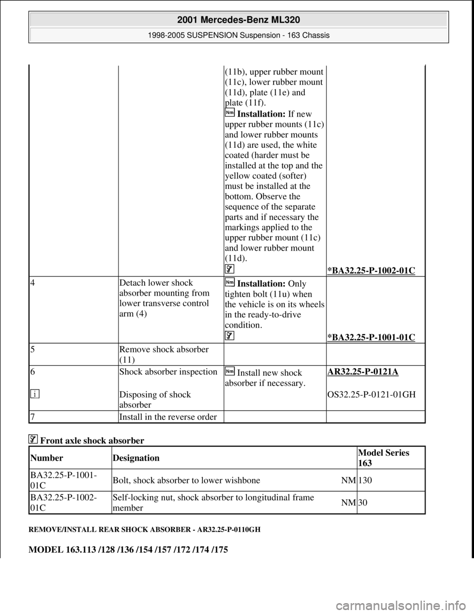
Front axle shock absorber
REMOVE/INSTALL REAR SHOCK ABSORBER - AR32.25-P-0110GH
MODEL 163.113 /128 /136 /154 /157 /172 /174 /175
(11b), upper rubber mount
(11c), lower rubber mount
(11d), plate (11e) and
plate (11f).
Installation: If new
upper rubber mounts (11c)
and lower rubber mounts
(11d) are used, the white
coated (harder must be
installed at the top and the
yellow coated (softer)
must be installed at the
bottom. Observe the
sequence of the separate
parts and if necessary the
markings applied to the
upper rubber mount (11c)
and lower rubber mount
(11d).
*BA32.25-P-1002-01C
4Detach lower shock
absorber mounting from
lower transverse control
arm (4) Installation: Only
tighten bolt (11u) when
the vehicle is on its wheels
in the ready-to-drive
condition.
*BA32.25-P-1001-01C
5Remove shock absorber
(11)
6Shock absorber inspection Install new shock
absorber if necessary.AR32.25-P-0121A
Disposing of shock
absorber OS32.25-P-0121-01GH
7Install in the reverse order
NumberDesignationModel Series
163
BA32.25-P-1001-
01CBolt, shock absorber to lower wishboneNM130
BA32.25-P-1002-
01CSelf-locking nut, shock absorber to longitudinal frame
memberNM30
2001 Mercedes-Benz ML320
1998-2005 SUSPENSION Suspension - 163 Chassis
me
Saturday, October 02, 2010 3:37:35 PMPage 15 © 2006 Mitchell Repair Information Company, LLC.
Page 3928 of 4133
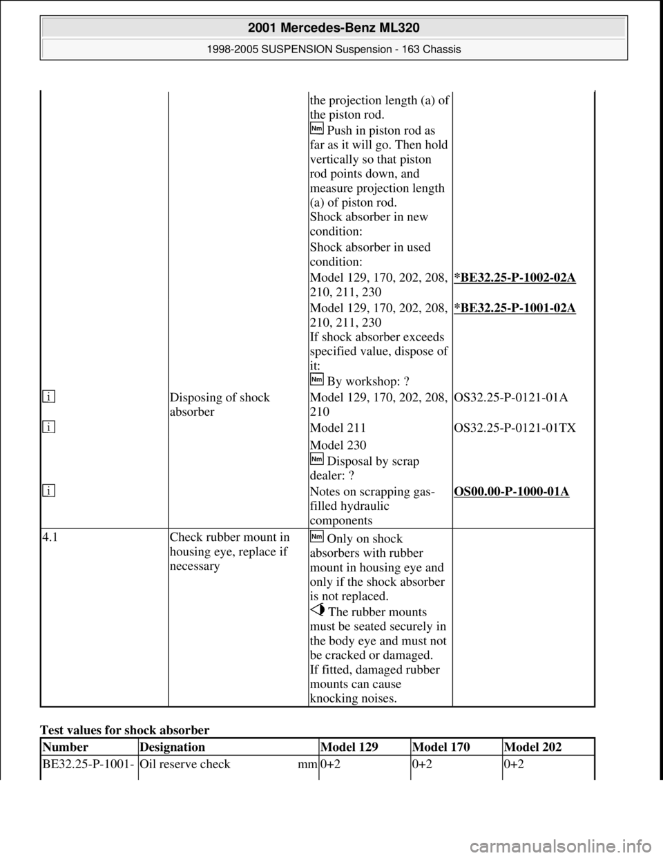
Test values for shock absorber
the projection length (a) of
the piston rod.
Push in piston rod as
far as it will go. Then hold
vertically so that piston
rod points down, and
measure projection length
(a) of piston rod.
Shock absorber in new
condition:
Shock absorber in used
condition:
Model 129, 170, 202, 208,
210, 211, 230*BE32.25-P-1002-02A
Model 129, 170, 202, 208,
210, 211, 230
If shock absorber exceeds
specified value, dispose of
it:
By workshop: ?*BE32.25-P-1001-02A
Disposing of shock
absorberModel 129, 170, 202, 208,
210OS32.25-P-0121-01A
Model 211OS32.25-P-0121-01TX
Model 230
Disposal by scrap
dealer: ?
Notes on scrapping gas-
filled hydraulic
componentsOS00.00-P-1000-01A
4.1Check rubber mount in
housing eye, replace if
necessary Only on shock
absorbers with rubber
mount in housing eye and
only if the shock absorber
is not replaced.
The rubber mounts
must be seated securely in
the body eye and must not
be cracked or damaged.
If fitted, damaged rubber
mounts can cause
knocking noises.
NumberDesignationModel 129Model 170Model 202
BE32.25-P-1001- Oil reserve check mm0+20+20+2
2001 Mercedes-Benz ML320
1998-2005 SUSPENSION Suspension - 163 Chassis
me
Saturday, October 02, 2010 3:37:36 PMPage 20 © 2006 Mitchell Repair Information Company, LLC.
Page 3999 of 4133
2001 SYSTEM WIRING DIAGRAMS
Mercedes-Benz - ML320
USING MITCHELL1'S WIRING DIAGRAMS
For information on using these wiring diagrams, see USING MITCHELL1'S SYSTEM WIRING
DIAGRAMS article.
AIR CONDITIONING
2001 Mercedes-Benz ML320
2001 SYSTEM WIRING DIAGRAMS Mercedes-Benz - ML320
2001 Mercedes-Benz ML320
2001 SYSTEM WIRING DIAGRAMS Mercedes-Benz - ML320
me
Saturday, October 02, 2010 3:27:58 PMPage 1 © 2006 Mitchell Repair Information Company, LLC.
me
Saturday, October 02, 2010 3:28:05 PMPage 1 © 2006 Mitchell Repair Information Company, LLC.