ECO mode MERCEDES-BENZ ML320 1997 Complete Owner's Guide
[x] Cancel search | Manufacturer: MERCEDES-BENZ, Model Year: 1997, Model line: ML320, Model: MERCEDES-BENZ ML320 1997Pages: 4133, PDF Size: 88.89 MB
Page 377 of 4133
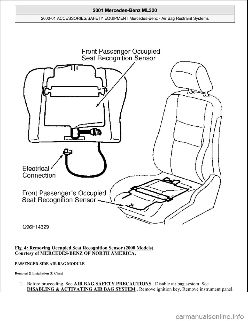
Fig. 4: Removing Occupied Seat Recognition Sensor (2000 Models)
Courtesy of MERCEDES-BENZ OF NORTH AMERICA.
PASSENGER-SIDE AIR BAG MODULE
Removal & Installation (C Class)
1. Before proceeding, See AIR BAG SAFETY PRECAUTIONS . Disable air bag system. See
DISABLING & ACTIVATI NG AIR BAG SYSTEM
. Remove ignition key. Remove instrument panel.
2001 Mercedes-Benz ML320
2000-01 ACCESSORIES/SAFETY EQUIPMENT Merc edes-Benz - Air Bag Restraint Systems
me
Saturday, October 02, 2010 3:44:45 PMPage 13 © 2006 Mitchell Repair Information Company, LLC.
Page 384 of 4133
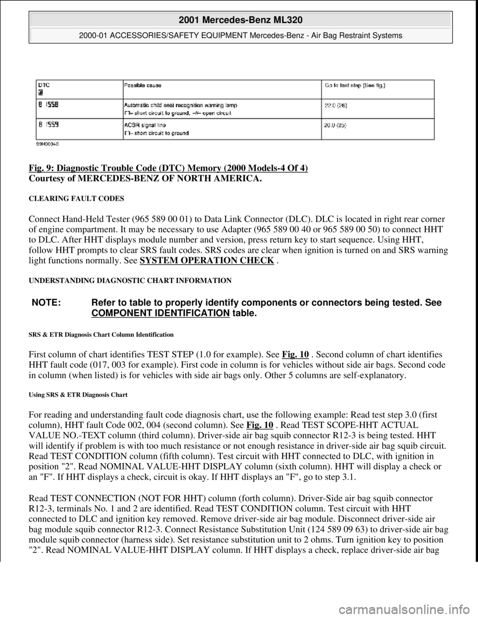
Fig. 9: Diagnostic Trouble Code (DTC) Memory (2000 Models-4 Of 4)
Courtesy of MERCEDES-BENZ OF NORTH AMERICA.
CLEARING FAULT CODES
Connect Hand-Held Tester (965 589 00 01) to Data Link Connector (DLC). DLC is located in right rear corner
of engine compartment. It may be necessary to use Adapter (965 589 00 40 or 965 589 00 50) to connect HHT
to DLC. After HHT displa ys module number and version, press return key to start sequence. Using HHT,
follow HHT prompts to clear SRS faul t codes. SRS codes are clear when ignition is turned on and SRS warning
light functions normally. See SYSTEM OPERATION CHECK
.
UNDERSTANDING DIAGNOSTIC CHART INFORMATION
SRS & ETR Diagnosis Chart Column Identification
First column of chart identifies TEST STEP (1.0 for example). See Fig. 10 . Second column of chart identifies
HHT fault code (017, 003 for example). First code in column is for ve hicles without side air bags. Second code
in column (when listed) is for ve hicles with side air bags only. Ot her 5 columns are self-explanatory.
Using SRS & ETR Diagnosis Chart
For reading and understanding fault code diagnosis chart, use the following example: Read test step 3.0 (first
column), HHT fault Code 002, 004 (second column). See Fig. 10
. Read TEST SCOPE-HHT ACTUAL
VALUE NO.-TEXT column (third column). Driver-side air bag squib connector R12-3 is being tested. HHT
will identify if problem is with too much resistance or not enough resistance in driver-side air bag squib circuit.
Read TEST CONDITION column (fifth column). Test ci rcuit with HHT connected to DLC, with ignition in
position "2". Read NOMINAL VALUE-HHT DISPLAY column (sixth column). HHT will display a check or
an "F". If HHT displays a check, circuit is okay. If HHT displays an "F", go to step 3.1.
Read TEST CONNECTION (NOT FOR HHT) column (fort h column). Driver-Side air bag squib connector
R12-3, terminals No. 1 and 2 are id entified. Read TEST CONDITION column. Test circuit with HHT
connected to DLC and igni tion key removed. Remove driver-side air bag module. Disconnect driver-side air
bag module squib connector R12-3. Conn ect Resistance Substitution Unit (124 589 09 63) to driver-side air bag
module squib connector (harness side). Set resistance substitution unit to 2 ohms. Turn ignition key to position
"2". Read NOMINAL VALUE-HHT DISPLAY column. If HHT displa
ys a check, replace driver-side air bag
NOTE: Refer to table to properly identify components or connectors being tested. See
COMPONENT IDENTIFICATION
table.
2001 Mercedes-Benz ML320
2000-01 ACCESSORIES/SAFETY EQUIPMENT Merc edes-Benz - Air Bag Restraint Systems
me
Saturday, October 02, 2010 3:44:46 PMPage 20 © 2006 Mitchell Repair Information Company, LLC.
Page 385 of 4133
module. If HHT displays an "F", go to step 3.2.
Read TEST CONNECTION (NOT FOR HHT) column. Horn -air bag clockspring connector A45x1, terminals
No. 1 and 2 are identified. Read TEST CONDITION column. Test circuit with HHT connected to DLC.
Remove ignition key. Connect Resist ance Substitution Unit (124 589 09 63 00) to horn-air bag clockspring
connector A45x1. Set resistance s ubstitution unit to 2 ohms. Read NOMINAL VALUE-HHT DISPLAY
column. If HHT displays a check, check horn-air ba g clockspring for continuity. Replace horn-air bag
clockspring as necessary. If HHT displays an "F", go to step 3.4.
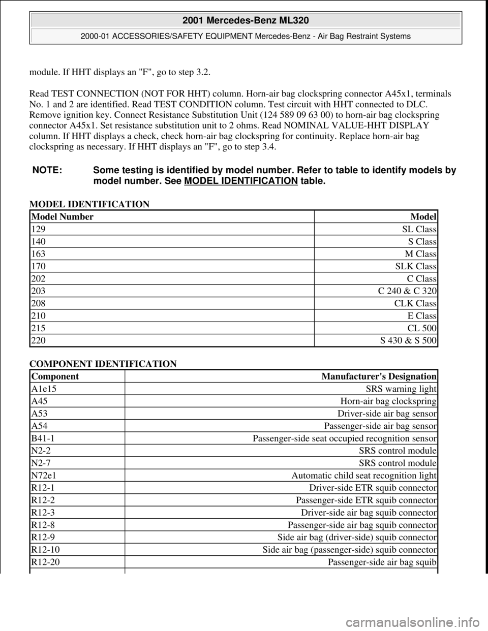
MODEL IDENTIFICATION
COMPONENT IDENTIFICATION
NOTE: Some testing is identified
by model number. Refer to table to identify models by
model number. See MO DEL IDENTIFICATION
table.
Model NumberModel
129SL Class
140S Class
163M Class
170SLK Class
202C Class
203C 240 & C 320
208CLK Class
210E Class
215CL 500
220S 430 & S 500
ComponentManufacturer's Designation
A1e15SRS warning light
A45Horn-air bag clockspring
A53Driver-side air bag sensor
A54Passenger-side air bag sensor
B41-1Passenger-side seat occupied recognition sensor
N2-2SRS control module
N2-7SRS control module
N72e1Automatic child seat recognition light
R12-1Driver-side ETR squib connector
R12-2Passenger-side ETR squib connector
R12-3Driver-side air bag squib connector
R12-8Passenger-side air bag squib connector
R12-9Side air bag (driver-side) squib connector
R12-10Side air bag (passenge r-side) squib connector
R12-20Passenger-side air bag squib
2001 Mercedes-Benz ML320
2000-01 ACCESSORIES/SAFETY EQUIPMENT Merc edes-Benz - Air Bag Restraint Systems
me
Saturday, October 02, 2010 3:44:46 PMPage 21 © 2006 Mitchell Repair Information Company, LLC.
Page 386 of 4133
CONTROL MODULE PROGRAMMING
After control module replacement, SRS warning light will blink or illuminate continuously. This indicates need
to program and set paramete rs of SRS control module. This process requires use of Hand-Held Tester (965 589
00 01). During programming, the follow ing conditions need to be met:
Vehicles Without Side Air Bag
Version with passenger-side air bag module, when replac ing SRS control module is to be set to YES when
programming control module. Version with seat belt buckle switch is to be programmed NO.
Vehicles With Side Air Bag
Version is set to YES when replacing SRS control module. Version with seat belt buckle switch is set to YES.
Seat occupation recogni tion is set to YES.
Parameters
After programming, SRS warning light wi ll continue to blink, indicating need to set parameters. Currently,
parameters set is identical for all models.
DIAGNOSTIC TESTS
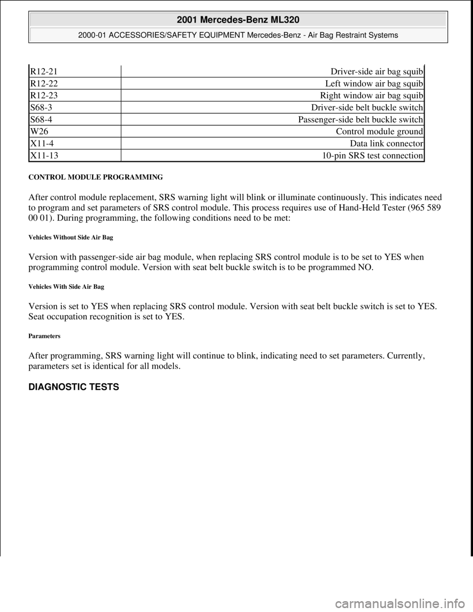
R12-21Driver-side air bag squib
R12-22Left window air bag squib
R12-23Right window air bag squib
S68-3Driver-side belt buckle switch
S68-4Passenger-side belt buckle switch
W26Control module ground
X11-4Data link connector
X11-1310-pin SRS test connection
2001 Mercedes-Benz ML320
2000-01 ACCESSORIES/SAFETY EQUIPMENT Merc edes-Benz - Air Bag Restraint Systems
me
Saturday, October 02, 2010 3:44:46 PMPage 22 © 2006 Mitchell Repair Information Company, LLC.
Page 430 of 4133
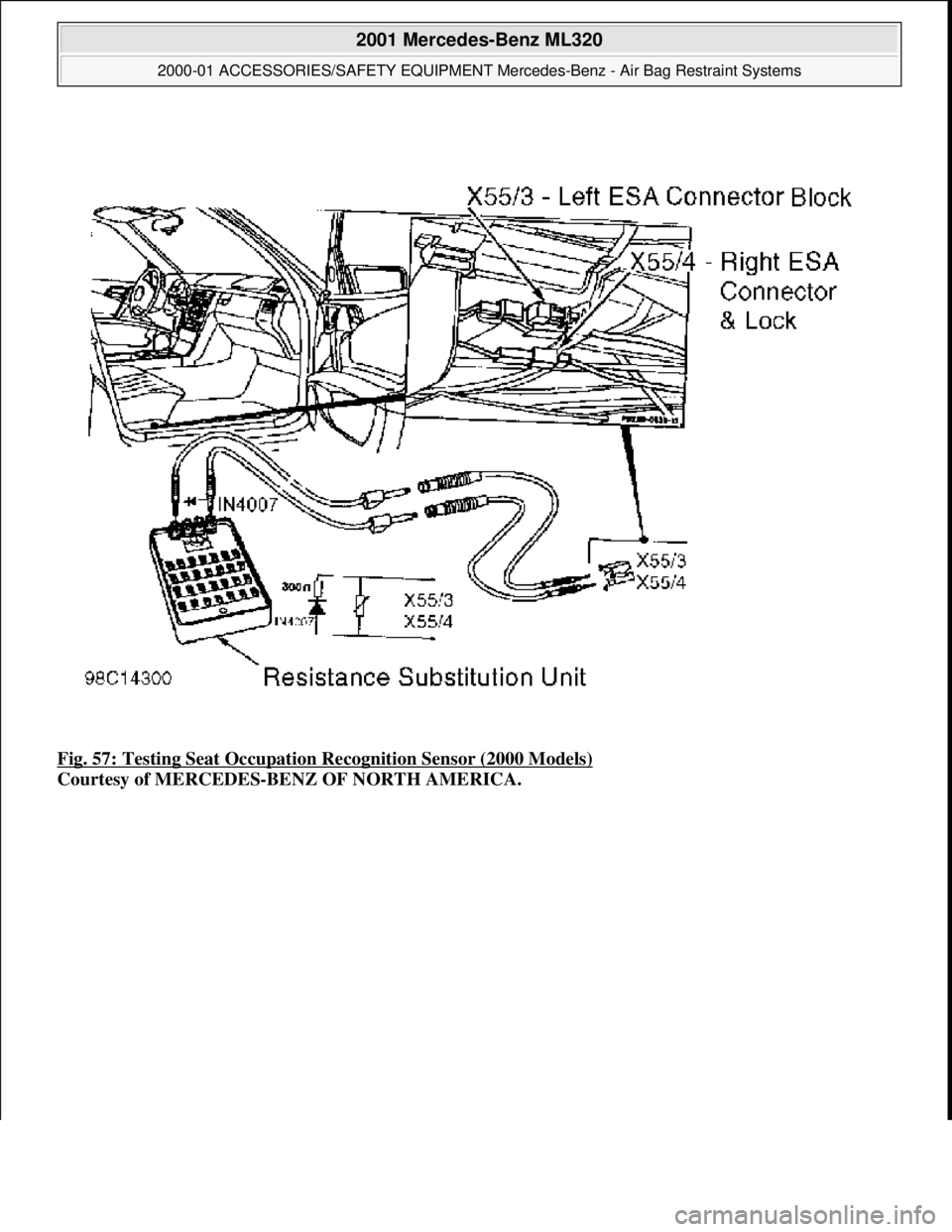
Fig. 57: Testing Seat Occupation Recognition Sensor (2000 Models)
Courtesy of MERCEDES-BENZ OF NORTH AMERICA.
2001 Mercedes-Benz ML320
2000-01 ACCESSORIES/SAFETY EQUIPMENT Merc edes-Benz - Air Bag Restraint Systems
me
Saturday, October 02, 2010 3:44:46 PMPage 66 © 2006 Mitchell Repair Information Company, LLC.
Page 431 of 4133
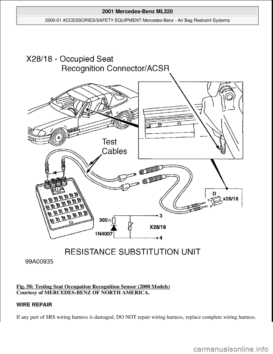
Fig. 58: Testing Seat Occupation Recognition Sensor (2000 Models)
Courtesy of MERCEDES-BENZ OF NORTH AMERICA.
WIRE REPAIR
If any part of SRS wiring harness is damaged, DO NOT repair wiring harness, replace complete wiring harness.
2001 Mercedes-Benz ML320
2000-01 ACCESSORIES/SAFETY EQUIPMENT Merc edes-Benz - Air Bag Restraint Systems
me
Saturday, October 02, 2010 3:44:46 PMPage 67 © 2006 Mitchell Repair Information Company, LLC.
Page 474 of 4133
7
Introduction Product information
Kindly observe the following in your own best interest:
We recommend using Mercedes-Benz original parts as well as conversion parts and accessories
explicitly approved by us for your vehicle model.
We have tested these parts to determine their reliability, safety and their special
suitability for Mercedes-Benz vehicles.
We are unable to make an assessment for other products and therefore cannot be held responsible
for them, even if in individual cases an official approval or authorization by governmental or other
agencies should exist. Use of such parts and accessories could adversely affect the safety,
performance or reliability of your vehicle. Please do not use them.
Mercedes-Benz original parts as well as conversion parts and accessories approved by us are available
at your authorized Mercedes-Benz Light Truck Center where you will receive comprehensive information, also on
permissible technical modifications, and where proper installation will be performed.
Page 503 of 4133

36
Tow-away protection
Te ch n ica l
data
Instruments
and controls Operation
Driving Instrument
cluster display Practical hints Car care Index
Tow-away alarm and glass breakage sensor
The switch is located in the overhead console.
The tow-away alarm and glass breakage sensor are part
of the antitheft alarm system.
Once the alarm system has been armed, the turn signal
lamps will flash rapidly and the horn will sound when
someone attempts to raise the vehicle, or breaks a
window and reaches into the passenger compartment. The alarm will last approximately 3 minutes in the form
of rapidly flashing turn signal lamps. At the same time
the horn will sound for approximately 30 seconds. The
alarm will stay on even if the vehicle is immediately
lowered.
If the alarm stays on for more than 20 seconds, an
emergency call is initiated automatically. See Tele Aid
on page 148.
To prevent triggering the tow-away alarm feature, switch
off the tow-away alarm and glass breakage sensor before
towing the vehicle, or when parking on a surface subject
to movement, such as a ferry or auto train.
To do so, turn key in steering lock to position 1, then
return it to position 0 and remove key from steering
lock.
Within 30 seconds, push left or right button. (On
vehicles equipped with optional trip computer, push
RESET or MODE button, display shows OFF.)
Exit vehicle, and lock vehicle with remote control.
The tow-away alarm and glass breakage sensor remain
switched off until the key is inserted in steering lock
and turned to position 1.
Page 507 of 4133
40
Seats
Te ch n ica l
data
Instruments
and controls Operation
Driving Instrument
cluster display Practical hints Car care Index
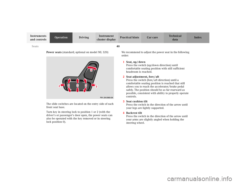
Power seats (standard; optional on model ML 320)
The slide switches are located on the entry side of each
front seat base.
Turn key in steering lock to position 1 or 2 (with the
driver’s or passenger’s door open, the power seats can
also be operated with the key removed or in steering
lock position 0). We recommend to adjust the power seat in the following
order:
1 Seat, up / down
Press the switch (up/down direction) until
comfortable seating position with still sufficient
headroom is reached.
2 Seat adjustment, fore / aft
Press the switch (fore / aft direction) until a
comfortable seating position is reached that still
allows you to reach the accelerator / brake pedal
safely. The position should be as far rearward as
possible, consistent with ability to properly operate
controls.
3 Seat cushion tilt
Press the switch in the direction of the arrow until
your legs are lightly supported.
4 Backrest tilt
Press the switch in the direction of the arrow until
your arms are slightly angled when holding the
steering wheel.
Page 509 of 4133
42
Seats
Te ch n ica l
data
Instruments
and controls Operation
Driving Instrument
cluster display Practical hints Car care Index
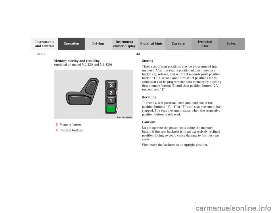
Memory storing and recalling
(optional on model ML 320 and ML 430)
5 Memory button
6 Position buttons Storing
Three sets of seat positions may be programmed into
memory. After the seat is positioned, push memory
button (5), release, and within 3 seconds push position
button “1”. A second and third set of positions for the
same seat can be programmed into memory by pushing
first memory button (5) and then position button “2”,
respectively “3”.
Recalling
To recall a seat position, push and hold one of the
position buttons “1”, “2” or “3” until seat movement has
stopped. The seat movement stops when the respective
position button is released.
Caution!
Do not operate the power seats using the memory
button if the seat backrest is in an excessively reclined
position. Doing so could cause damage to front or rear
seats.
First move the backrest to an upright position.