radio MERCEDES-BENZ ML320 1997 Complete Service Manual
[x] Cancel search | Manufacturer: MERCEDES-BENZ, Model Year: 1997, Model line: ML320, Model: MERCEDES-BENZ ML320 1997Pages: 4133, PDF Size: 88.89 MB
Page 1177 of 4133
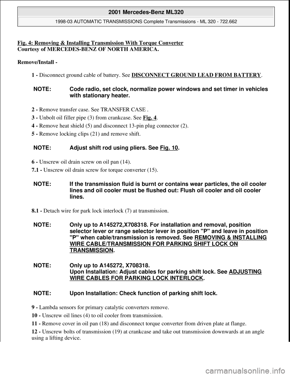
Fig. 4: Removing & Installing Transmission With Torque Converter
Courtesy of MERCEDES-BENZ OF NORTH AMERICA.
Remove/Install -
1 - Disconnect ground cable of battery. See DISCONNECT GROUND LEAD FROM BATTERY
.
2 - Remove transfer case. See TRANSFER CASE .
3 - Unbolt oil filler pipe (3) from crankcase. See Fig. 4
.
4 - Remove heat shield (5) and disconnect 13-pin plug connector (2).
5 - Remove locking clips (21) and remove shift.
6 - Unscrew oil drain screw on oil pan (14).
7.1 - Unscrew oil drain screw for torque converter (15).
8.1 - Detach wire for park lock interlock (7) at transmission.
9 - Lambda sensors for primary catalytic converters remove.
10 - Unscrew oil lines (4) to oil cooler from transmission.
11 - Remove cover in oil pan (18) and disconnect torque converter from driven plate at flange.
12 - Unscrew bolts of transmission (19) at crankcase and take out transmission downwards at an angle
using a lifting device. NOTE: Code radio, set clock, normalize power windows and set timer in vehicles
with stationary heater.
NOTE: Adjust shift rod using pliers. See Fig. 10
.
NOTE: If the transmission fluid is burnt or contains wear particles, the oil cooler
lines and oil cooler must be flushed out: Flush oil cooler and oil cooler
lines.
NOTE: Only up to A145272,X708318. For installation and removal, position
selector lever or range selector lever in position "P" and leave in position
"P" when cable/transmission is removed. See REMOVING & INSTALLING
WIRE CABLE/TRANSMISSION FOR PARKING SHIFT LOCK ON
TRANSMISSION.
NOTE: Only up to A145272, X708318.
Upon Installation: Adjust cables for parking shift lock. See ADJUSTING
WIRE CABLES FOR PARKING LOCK INTERLOCK.
NOTE: Upon Installation: Check function of parking shift lock.
2001 Mercedes-Benz ML320
1998-03 AUTOMATIC TRANSMISSIONS Complete Transmissions - ML 320 - 722.662
me
Saturday, October 02, 2010 3:15:25 PMPage 8 © 2006 Mitchell Repair Information Company, LLC.
Page 1184 of 4133
Connect ground cable.
4 - Code radio.
5 - Set time at instrument cluster
6.1 - Activate steering angle sensor.
7.1 - Synchronize tilt/slide sunroof.
8.1 - Synchronize lamella (thin plate) sliding roof.
9.1 - Synchronize power windows.
Torque Specification; Nut Of Ground Cable To Body NOTE: After opening the vehicle wait for at least 4 minutes before disconnecting
the battery otherwise the alarm will be triggered.
NOTE: Model 163: Tighten the nut (5) of the ground line (1) to the specified
torque. Perform work described below only when quiescent current
retention unit was not connected. Model Series 163 see Torque
Specification; Nut Of Ground Cable To Body.
NOTE: MB (models 163).
Hi-Line, premium with Bose (model 163).
NOTE: If necessary set time at stationary heater timer.
NOTE: Model 163 with Code 414.
Open tilt/slide sunroof and hold down switch. Sliding/pop-up roof
mechanism moves to end position, pulls back 1/4 turn and stops.
NOTE: Open tilt/slide sunroof and hold down switch. Sliding/pop-up roof
mechanism moves to end position, pulls back 1/4 turn and stops.
NOTE: Model 163 as of VIN A289565, X754620.
Press power windows switch up to the 1st pressure point and, after
reaching the upper end position of the window, keep pressed for further 5
seconds.
NumberDesignationModel Series 163
BA54.10--P-1001--01ANut of ground cable to bodyNM18
2001 Mercedes-Benz ML320
1998-03 AUTOMATIC TRANSMISSIONS Complete Transmissions - ML 320 - 722.662
me
Saturday, October 02, 2010 3:15:25 PMPage 15 © 2006 Mitchell Repair Information Company, LLC.
Page 1496 of 4133
1998-2005 ACCESSORIES & BODY, CAB
Electrical System - Body - 163 Chassis
GENERAL INFORMATION
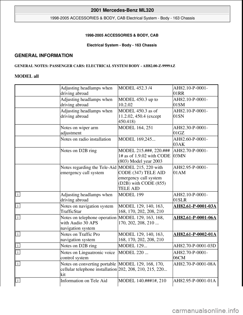
GENERAL NOTES: PASSENGER CARS: ELECTRICAL SYSTEM BODY - AH82.00-Z-9999AZ
MODEL all
Adjusting headlamps when
driving abroadMODEL 452.3 /4AH82.10-P-0001-
01RR
Adjusting headlamps when
driving abroadMODEL 450.3 up to
10.2.02AH82.10-P-0001-
01SM
Adjusting headlamps when
driving abroadMODEL 450.3 as of
11.2.02, 450.4 (except
450.418)AH82.10-P-0001-
01SN
Notes on wiper arm
adjustmentMODEL 164, 251AH82.30-P-0001-
01GZ
Notes on radio installationMODEL 169,245...AH82.60-P-0001-
03AK
Notes on D2B ringMODEL 215.###, 220.###
1# as of 1.9.02 with CODE
(803) Model year 2003AH82.70-P-0001-
03MN
Notes regarding the Tele-Aid
emergency call systemMODEL 215, 220 with
CODE (347) TELE AID
emergency call system
(D2B) with CODE (855)
TELE AIDAH82.95-P-0001-
01AM
Adjusting headlamps when
driving abroadMODEL 199AH82.10-P-0001-
01SLR
Notes on navigation system
TrafficStarMODEL 129, 140, 163,
168, 170, 202, 208, 210AH82.61-P-0001-03A
Notes on telephone operation
with Audio 30 APS
navigation systemMODEL 129, 163, 168,
170, 202, 208, 210 ...AH82.61-P-0001-06A
Notes on Traffic Pro
navigation systemMODEL 129, 140, 163,
168, 170, 202, 208, 210AH82.61-P-0002-01A
Notes on D2B ringMODEL 129...AH82.70-P-0001-03D
Notes on Linguatronic voice
control systemMODEL 220 ...AH82.70-P-0001-
06CM
Notes on converting portable
cellular telephone installation
kitMODEL 129, 168, 170,
202, 208, 210, 215, 220...AH82.70-P-0001-08A
Information on Tele Aid MODEL 140.###1#, 210 AH82.95-P-0001-01A
2001 Mercedes-Benz ML320
1998-2005 ACCESSORIES & BODY, CAB Electrical System - Body - 163 Chassis
2001 Mercedes-Benz ML320
1998-2005 ACCESSORIES & BODY, CAB Electrical System - Body - 163 Chassis
me
Saturday, October 02, 2010 3:30:03 PMPage 1 © 2006 Mitchell Repair Information Company, LLC.
me
Saturday, October 02, 2010 3:30:18 PMPage 1 © 2006 Mitchell Repair Information Company, LLC.
Page 1497 of 4133
emergency call systemwith CODE (348) TELE
AID emergency call system
Notes regarding the taxi
emergency call systemMODEL 140,202,210,220...AH82.95-P-0002-01A
Adjusting headlamps when
driving abroadMODEL 164, 169, 171,
203, 209, 211, 215, 216,
219, 220, 221, 230, 245,
251 ...AH82.10-P-0001-01A
Adjust headlamps when
driving abroadMODEL 454.0AH82.10-P-0001-
01FF
Adjusting headlamps when
driving abroadMODEL 451.3/4AH82.10-P-0001-
01MCC
Retrofitting xenon headlampsMODEL 129, 140, 202,
210, 220 ...AH82.10-P-1003-01A
Retrofitting xenon headlampsMODEL 210.###1# as of
1.7.99AH82.10-P-1003-01F
Notes on retrofitting xenon
headlampsMODEL 203AH82.10-P-1003-01P
Notes on installing taxi/rental
vehicle equipmentMODEL 245 ...AH82.25-P-0001-
01BK
Notes on installing rental
vehicle equipmentMODEL 221.0##/1##1#
except CODE (498) Japan
version except CODE (494)
USA versionAH82.25-P-0001-
02SX
Notes on mirror taximeterMODEL 202, 203.0, 210,
220 with CODE (450) Taxi
versionAH82.25-P-1000-02P
Notes on wiper arm
adjustmentMODEL 171.4, 203, 209,
211, 215, 220, 230, 240AH82.30-P-0001-01A
Notes on wiper arm
adjustmentMODEL 129,202,208,210AH82.30-P-0001-01B
Notes on wiper arm
adjustmentMODEL 219.3AH82.30-P-0001-
01TX
Notes on COMAND
software statusMODEL 215, 220 with
CODE (352a) COMAND
operating and display
system bei APS der 3.
GerategenerationAH82.60-P-0001-01A
Notes on radio installationMODEL 203 ...AH82.60-P-0001-03P
Notes on removal/installation
of the fiber optical cable for
the Media Oriented System
Transport (MOST)MODEL 211.0/2AH82.60-P-0001-06T
Notes on auto-pilot systemMODEL 170AH82.61-P-0001-01A
2001 Mercedes-Benz ML320
1998-2005 ACCESSORIES & BODY, CAB Electrical System - Body - 163 Chassis
me
Saturday, October 02, 2010 3:30:04 PMPage 2 © 2006 Mitchell Repair Information Company, LLC.
Page 1498 of 4133
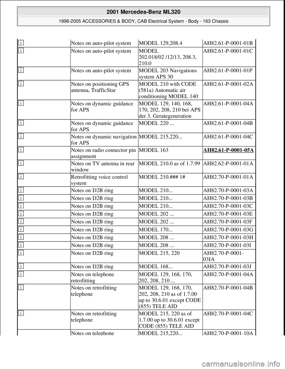
Notes on auto-pilot systemMODEL 129,208.4AH82.61-P-0001-01B
Notes on auto-pilot systemMODEL
202.018/02 /12/13, 208.3,
210.0AH82.61-P-0001-01C
Notes on auto-pilot systemMODEL 203 Navigations
system APS 30AH82.61-P-0001-01P
Notes on positioning GPS
antenna, TrafficStarMODEL 210 with CODE
(581a) Automatic air
conditioning MODEL 140AH82.61-P-0001-02A
Notes on dynamic guidance
for APSMODEL 129, 140, 168,
170, 202, 208, 210 bei APS
der 3. GerategenerationAH82.61-P-0001-04A
Notes on dynamic guidance
for APSMODEL 220 ...AH82.61-P-0001-04B
Notes on dynamic navigation
for APSMODEL 215,220...AH82.61-P-0001-04C
Notes on radio connector pin
assignmentMODEL 163AH82.61-P-0001-05A
Notes on TV antenna in rear
windowMODEL 210.0 as of 1.7.99AH82.62-P-0001-01A
Retrofitting voice control
systemMODEL 210.### 1#AH82.70-P-0001-01A
Notes on D2B ringMODEL 210...AH82.70-P-0001-03A
Notes on D2B ringMODEL 210...AH82.70-P-0001-03B
Notes on D2B ringMODEL 210...AH82.70-P-0001-03C
Notes on D2B ringMODEL 202 ...AH82.70-P-0001-03E
Notes on D2B ringMODEL 202 ...AH82.70-P-0001-03F
Notes on D2B ringMODEL 170...AH82.70-P-0001-03G
Notes on D2B ringMODEL 208 ...AH82.70-P-0001-03H
Notes on D2B ringMODEL 208 ...AH82.70-P-0001-03I
Notes on D2B ringMODEL 215, 220AH82.70-P-0001-
03IA
Notes on D2B ringMODEL 168...AH82.70-P-0001-03J
Notes on telephone
retrofittingMODEL 129, 168, 170,
202, 208, 210 ...AH82.70-P-0001-04A
Notes on retrofitting
telephoneMODEL 129, 168, 170,
202, 208, 210 as of 1.7.00
up to 30.6.01 except CODE
(855) TELE AIDAH82.70-P-0001-04B
Notes on retrofitting
telephoneMODEL 215, 220 as of
1.7.00 up to 30.6.01 except
CODE (855) TELE AIDAH82.70-P-0001-04C
Notes on telephone MODEL 215,220...AH82.70-P-0001-10A
2001 Mercedes-Benz ML320
1998-2005 ACCESSORIES & BODY, CAB Electrical System - Body - 163 Chassis
me
Saturday, October 02, 2010 3:30:04 PMPage 3 © 2006 Mitchell Repair Information Company, LLC.
Page 1500 of 4133
Notes on installation of GPS antenna
The GPS antenna should be installed only in a vertical position with a maximum deviation of 10° from
horizontal.
The GPS antenna should always have a free view of the sky. Thermal insulated windows can significantly
reduce the function of the GPS antenna.
When installing the GPS antenna, always ensure that the arched surface points away from the vehicle.
Changing the installation location inside of the vehicle after the system is put into operation has no effect on the
GPS reception.
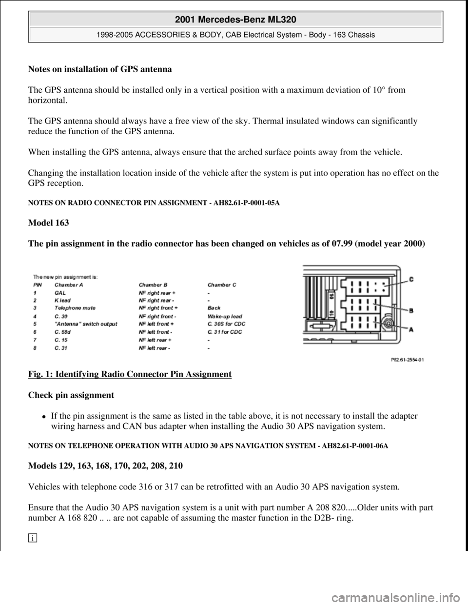
NOTES ON RADIO CONNECTOR PIN ASSIGNMENT - AH82.61-P-0001-05A
Model 163
The pin assignment in the radio connector has been changed on vehicles as of 07.99 (model year 2000)
Fig. 1: Identifying Radio Connector Pin Assignment
Check pin assignment
If the pin assignment is the same as listed in the table above, it is not necessary to install the adapter
wiring harness and CAN bus adapter when installing the Audio 30 APS navigation system.
NOTES ON TELEPHONE OPERATION WITH AUDIO 30 APS NAVIGATION SYSTEM - AH82.61-P-0001-06A
Models 129, 163, 168, 170, 202, 208, 210
Vehicles with telephone code 316 or 317 can be retrofitted with an Audio 30 APS navigation system.
Ensure that the Audio 30 APS navigation system is a unit with part number A 208 820.....Older units with part
number A 168 820 .. .. are not capable of assuming the master function in the D2B- ring.
2001 Mercedes-Benz ML320
1998-2005 ACCESSORIES & BODY, CAB Electrical System - Body - 163 Chassis
me
Saturday, October 02, 2010 3:30:04 PMPage 5 © 2006 Mitchell Repair Information Company, LLC.
Page 1501 of 4133
The Audio 30 APS does not have a number pad. For this reason, it is not possible to control the telephone over
the radio (see operating instructions).
On vehicles (as of approx. 07.99) with multifunction steering wheel (telephone control with keys on steering
wheel) this function is then also possible with the Audio 30 APS navigation system.
NOTES ON TRAFFIC PRO NAVIGATION SYSTEM - AH82.61-P-0002-01A
Models 129, 140, 163, 168, 170, 202, 208, 210
Customer information, installation position for GPS antenna
There are two different installation locations for the GSP antenna:
1. Standard GPS antenna from DaimlerChrysler on roof or trunk lid. This version offers the best reception
and is therefore preferable.
2. Use of magnetic antenna in vehicle passenger compartment. This version is part of the kit from the
Becker company and installation is described in Becker installation instructions.
Notes on installation of Becker GPS antenna
The GPS antenna can only be installed horizontally with a maximum deviation of 10° from horizontal.
The GPS antenna should always have an unobstructed view of the sky. Tinted windows can reduce the function
of the GPS antenna considerably.
When installing the GPS antenna always ensure that the arched surface of the antenna points upwards.
NOTES ON FIBER OPTIC CABLE - AH82.70-P-0001-02A
Model 129, 163, 168, 170, 202, 203, 208, 209, 210, 215, 220, 230, 414,
463.243/244/245/246/247/248/249/250/254/270/271/303/309/322/323/332/333/340/341
Illustrated on Model 202 sedan
2001 Mercedes-Benz ML320
1998-2005 ACCESSORIES & BODY, CAB Electrical System - Body - 163 Chassis
me
Saturday, October 02, 2010 3:30:04 PMPage 6 © 2006 Mitchell Repair Information Company, LLC.
Page 1502 of 4133
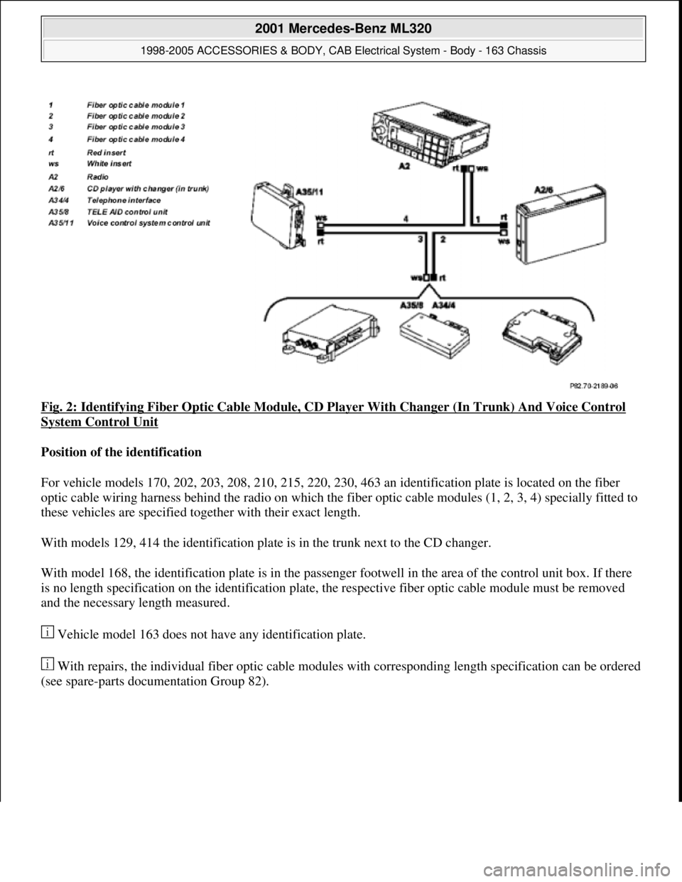
Fig. 2: Identifying Fiber Optic Cable Module, CD Player With Changer (In Trunk) And Voice Control
System Control Unit
Position of the identification
For vehicle models 170, 202, 203, 208, 210, 215, 220, 230, 463 an identification plate is located on the fiber
optic cable wiring harness behind the radio on which the fiber optic cable modules (1, 2, 3, 4) specially fitted to
these vehicles are specified together with their exact length.
With models 129, 414 the identification plate is in the trunk next to the CD changer.
With model 168, the identification plate is in the passenger footwell in the area of the control unit box. If there
is no length specification on the identification plate, the respective fiber optic cable module must be removed
and the necessary length measured.
Vehicle model 163 does not have any identification plate.
With repairs, the individual fiber optic cable modules with corresponding length specification can be ordered
(see spare-parts documentation Group 82).
2001 Mercedes-Benz ML320
1998-2005 ACCESSORIES & BODY, CAB Electrical System - Body - 163 Chassis
me
Saturday, October 02, 2010 3:30:04 PMPage 7 © 2006 Mitchell Repair Information Company, LLC.
Page 1503 of 4133
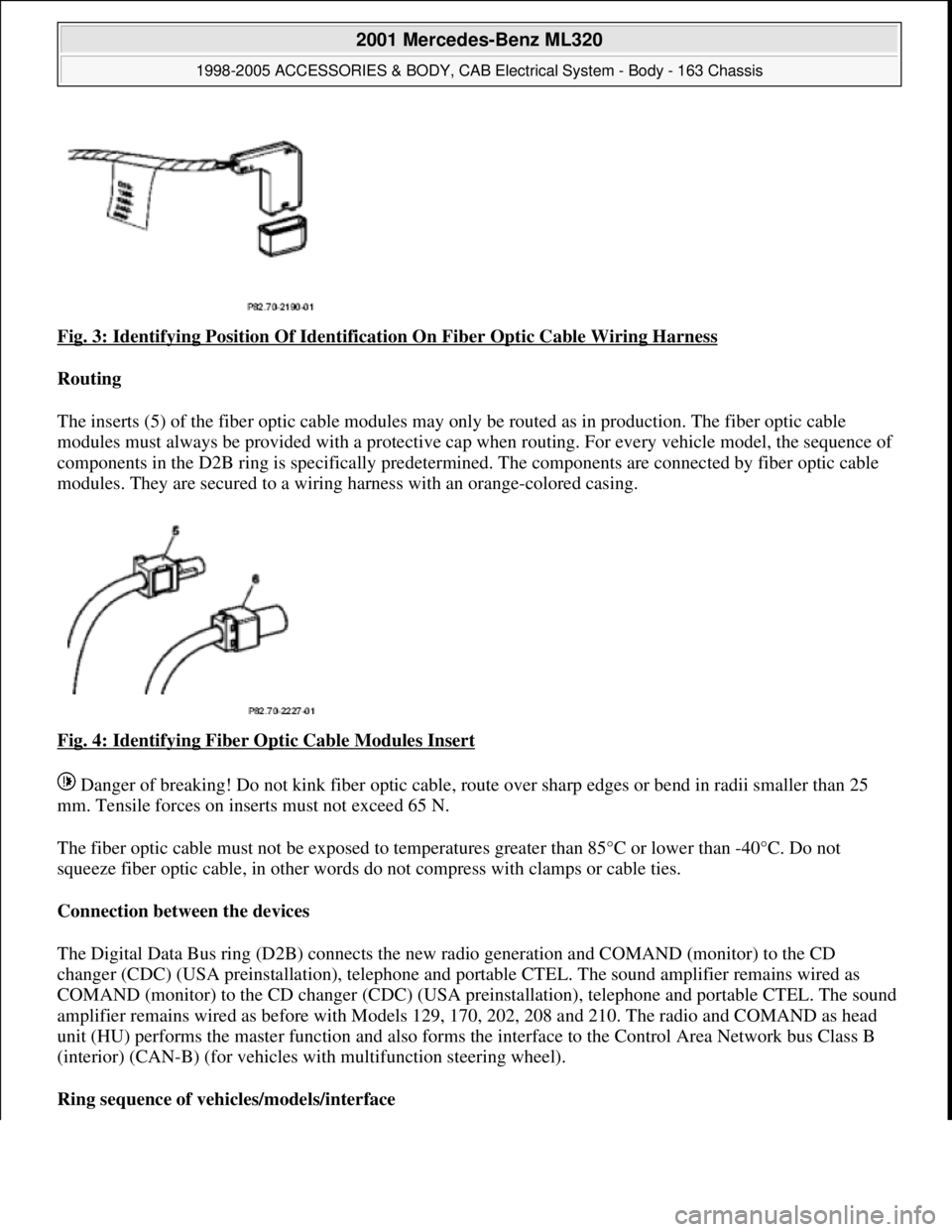
Fig. 3: Identifying Position Of Identification On Fiber Optic Cable Wiring Harness
Routing
The inserts (5) of the fiber optic cable modules may only be routed as in production. The fiber optic cable
modules must always be pr ovided with a protective cap when routing. For every vehicle model, the sequence of
components in the D2B ring is specifically predetermi ned. The components are connected by fiber optic cable
modules. They are secured to a wiring ha rness with an orange-colored casing.
Fig. 4: Identifying Fiber Optic Cable Modules Insert
Danger of breaking! Do not kink fiber optic cable, route over sharp edges or be nd in radii smaller than 25
mm. Tensile forces on inserts must not exceed 65 N.
The fiber optic cable must not be exposed to temperat ures greater than 85°C or lower than -40°C. Do not
squeeze fiber optic cable, in other words do not compress with clamps or cable ties.
Connection between the devices
The Digital Data Bus ring (D2B) connects the new ra dio generation and COMAND (monitor) to the CD
changer (CDC) (USA preinstallati on), telephone and portable CTEL. The sound amplifier remains wired as
COMAND (monitor) to the CD changer (CDC) (USA preinstallation), telephone and portable CTEL. The sound
amplifier remains wired as befo re with Models 129, 170, 202, 208 and 210. The radio and COMAND as head
unit (HU) performs the master function and also forms the interface to the Control Area Network bus Class B
(interior) (CAN-B) (for vehicles wi th multifunction steering wheel).
Ring sequence of vehi cles/models/interface
2001 Mercedes-Benz ML320
1998-2005 ACCESSORIES & BODY, CAB Electr ical System - Body - 163 Chassis
me
Saturday, October 02, 2010 3:30:04 PMPage 8 © 2006 Mitchell Repair Information Company, LLC.
Page 1505 of 4133
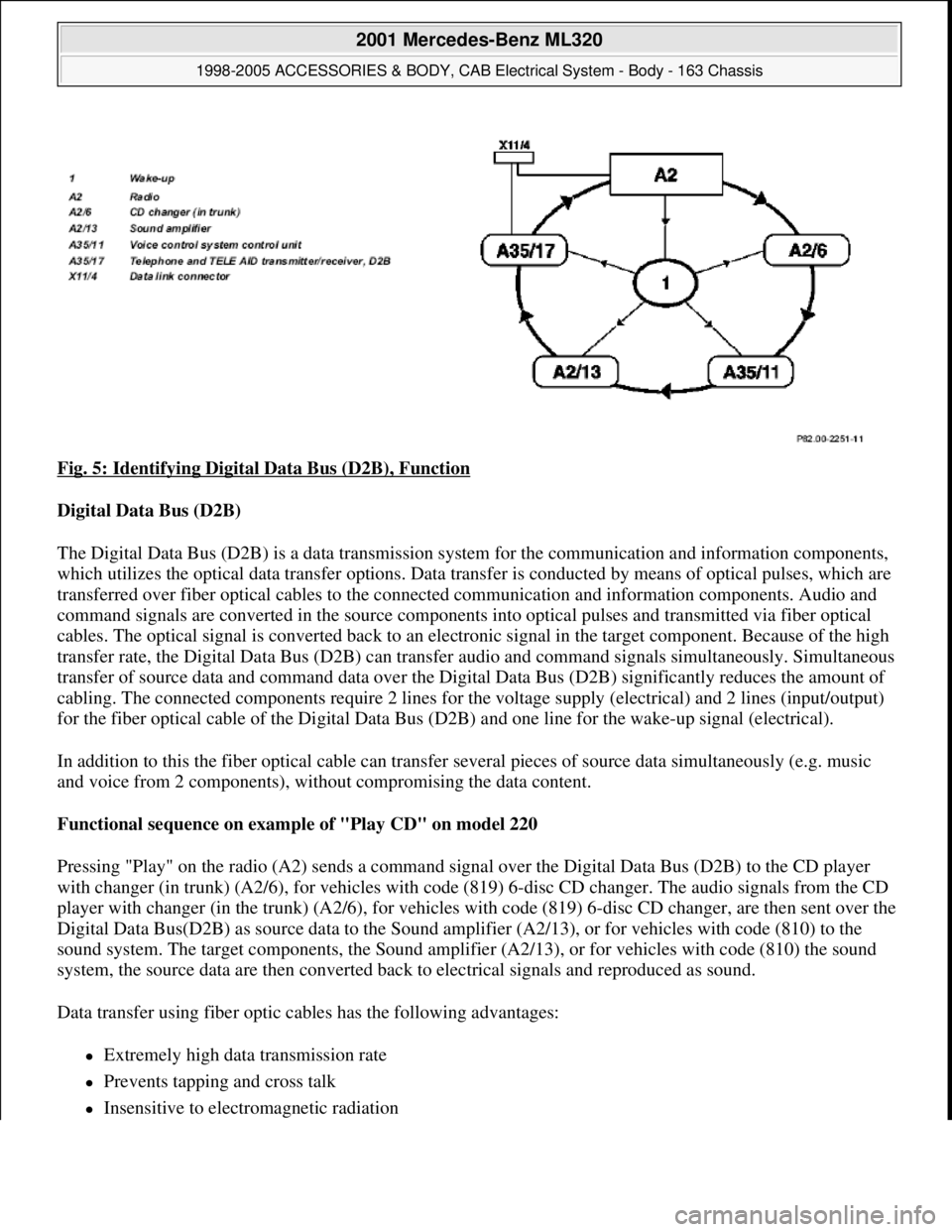
Fig. 5: Identifying Digital Data Bus (D2B), Function
Digital Data Bus (D2B)
The Digital Data Bus (D2B) is a data transmission system for the communication and information components,
which utilizes the optical data transfer options. Data transfer is conducted by means of optical pulses, which are
transferred over fiber optical cables to the connected communication and information components. Audio and
command signals are converted in the source components into optical pulses and transmitted via fiber optical
cables. The optical signal is converted back to an electronic signal in the target component. Because of the high
transfer rate, the Digital Data Bus (D2B) can transfer audio and command signals simultaneously. Simultaneous
transfer of source data and command data over the Digital Data Bus (D2B) significantly reduces the amount of
cabling. The connected components require 2 lines for the voltage supply (electrical) and 2 lines (input/output)
for the fiber optical cable of the Digital Data Bus (D2B) and one line for the wake-up signal (electrical).
In addition to this the fiber optical cable can transfer several pieces of source data simultaneously (e.g. music
and voice from 2 components), without compromising the data content.
Functional sequence on example of "Play CD" on model 220
Pressing "Play" on the radio (A2) sends a command signal over the Digital Data Bus (D2B) to the CD player
with changer (in trunk) (A2/6), for vehicles with code (819) 6-disc CD changer. The audio signals from the CD
player with changer (in the trunk) (A2/6), for vehicles with code (819) 6-disc CD changer, are then sent over the
Digital Data Bus(D2B) as source data to the Sound amplifier (A2/13), or for vehicles with code (810) to the
sound system. The target components, the Sound amplifier (A2/13), or for vehicles with code (810) the sound
system, the source data are then converted back to electrical signals and reproduced as sound.
Data transfer using fiber optic cables has the following advantages:
Extremely high data transmission rate
Prevents tapping and cross talk
Insensitive to electromagnetic radiation
2001 Mercedes-Benz ML320
1998-2005 ACCESSORIES & BODY, CAB Electrical System - Body - 163 Chassis
me
Saturday, October 02, 2010 3:30:04 PMPage 10 © 2006 Mitchell Repair Information Company, LLC.