remote control MERCEDES-BENZ ML320 1997 Complete Service Manual
[x] Cancel search | Manufacturer: MERCEDES-BENZ, Model Year: 1997, Model line: ML320, Model: MERCEDES-BENZ ML320 1997Pages: 4133, PDF Size: 88.89 MB
Page 608 of 4133
141
Garage door opener
Te ch n ica l
data
Instruments
and controls Operation
Driving Instrument
cluster display Practical hints Car care Index
For operation in the USA only: This device complies
with Part 15, Subpart C, Section 209 of the FCC Rules.
Operation is subject to the following two conditions:
(1) This device may not cause harmful interference, and
(2) this device must accept any interference received,
including interference that may cause undesired
operation.
WARNING: Changes or modification not expressly
approved by party responsible for compliance could void
the user’s authority to operate the equipment.
Programming or reprogramming the integrated
remote control:
1. Turn key in steering lock to position 1 or 2.
2. Hold the end of the hand-held transmitter of the device you wish to train approximately 2 to 5 inches
(5 cm to 12 cm) away from the surface of the
integrated remote control located on the overhead
console, keeping the indicator lamp in view. 3. Using both hands, simultaneously push the hand-
held transmitter button and the desired integrated
remote control button. Do not release the buttons
until completing step 4.
4. The indicator lamp on the integrated remote control will flash, first slowly and then rapidly. When the
indicator lamp flashes rapidly, both buttons may be
released (the rapid flashing lamp indicates
successful programming of the new frequency
signal). To program the remaining two buttons,
follow ste ps 1 through 4.
Note:
If after repeated attempts, you do not successfully
program the integrated remote control device to learn
the signal of the hand-held transmitter, the garage door
opener could be equipped with the “rolling code
feature”.
Page 609 of 4133
142
Garage door opener
Te ch n ica l
data
Instruments
and controls Operation
Driving Instrument
cluster display Practical hints Car care Index
Rolling code programming:
To train a garage door opener (or other rolling code
devices) with the rolling code feature, follow these
instructions after completing the “Programming”
portion of this text. (A second person may make the
following training procedures quicker and easier.)
1. Locate training button on the garage door opener motor head unit. Exact location and color of the
button may vary by garage door opener brand. If
there is difficulty locating the transmitting button,
reference to garage door opener operator’s manual.
2. Press “training” button on the garage door opener motor head unit (which activated the “training
light”).
Note:
Following step 2, there are 30 seconds to initiate
step 3. 3. Firmly press and release the programmed
integrated remote control transmit button. Press
and release same button a second time to complete
the training process. (Some garage door openers
may require you to do this procedure a third time to
complete the training.)
4. Confirm the garage door operation by pressing the programmed button on the integrated remote
control transmitter.
Canadian programming:
During programming, your hand-held transmitter may
automatically stop transmitting. Continue to press and
hold the integrated remote control transmitter button
(note steps 1 through 4 in the “Programming” portion)
while you press and re-press (“cycle”) your hand-held
transmitter every two seconds until the frequency
signal has been learned. The indicator lamp will flash
slowly and then rapidly after several seconds upon
successful training.
Page 610 of 4133
143
Garage door opener
Te ch n ica l
data
Instruments
and controls Operation
Driving Instrument
cluster display Practical hints Car care Index
Operation of remote control:
1. Turn key in steering lock to position 1 or 2.
2. Select and press the appropriate button to activate the remote controlled device. The integrated remote
control transmitter continues to send the signal as
long as the button is pressed – up to 20 seconds. Erasing the remote control memory:
1. Turn key in steering lock to position 1 or 2.
2. Simultaneously holding down the left and right side buttons for approximately 20 seconds, or until the
control lamp blinks rapidly, will erase the codes of
all three channels.
Page 615 of 4133
148
Tele Aid
Te ch n ica l
data
Instruments
and controls Operation
Driving Instrument
cluster display Practical hints Car care Index
Tele Aid
Important!
The initial activation of the Tele Aid system may only be
performed by completing the subscriber agreement and
placing an acquaintance call using the “SOS” button.
Failure to complete either of these steps will result in a
system that is not activated. If the system is not
activated the indicator lamp in the “SOS” button stays
on after turning electronic key in starter switch to
position 2 and the message “TELE AID – NOT
ACTIVATED” will be shown in the MCS display for
approx. 10 seconds.
If you have any questions regarding activation, please
call the Response Center at 1-800-756-9018 (in the USA)
or 1-888-923-8367 (in Canada).
( Tele matic Alarm Identification on Demand)
The Tele Aid system consists of three types of response;
automatic and manual emergency, roadside assistance
and information. The Tele Aid system is operational providing that the
vehicle’s battery is charged, properly connected, not
damaged and cellular and GPS coverage is available.
The speaker volume of a Tele Aid call can be adjusted
using the volume control on the MCS unit. To activate,
press the “SOS” button, the Roadside Assistance
button • or the Information button ¡, depending
on the type of response required.
Shortly after the completion of your Acquaintance Call,
you will receive a user ID and password via first call
mail. By visiting www.mbusa.com and selecting
“Tele Aid” (USA only), you will have access to account
information, remote door unlock, Info Services
* profile
and more.
* OptionalSystem self-check
Initially, after turning the key in steering lock to
position 2, malfunctions are detected and indicated (the
indicator lamps in the “SOS” button, the Roadside
Assistance button • and Information button ¡
stay on longer than 10 seconds or do not come on). The
message “TELE AID – PLEASE VISIT WORKSHOP”
appears in the MCS display.
Page 620 of 4133
153
Tele Aid
Te ch n ica l
data
Instruments
and controls Operation
Driving Instrument
cluster display Practical hints Car care Index
When the connection is established, the message
“ROADSIDE ASSISTANCE – CALL CONNECTED”
appears in the MCS display. The Tele Aid system will
transmit data generating the vehicle identification
number, model, color and location (subject to
availability of cellular and GPS signals).
While the call is connected, you can change to
navigation menu by pressing NAVI button on the MCS.
A voice connection between the Roadside Assistance
dispatcher and the occupants of the vehicle will be
established. When a voice connection is established the
audio system mutes and the message “TELE AID –
ROADSIDE ASSISTANCE CALL ACTIVE” appears in the
MCS display. The nature of the need for assistance can
then be described. The Mercedes-Benz Roadside
assistance dispatcher will either dispatch a qualified
Mercedes-Benz technician or arrange to tow your
vehicle to the nearest Mercedes-Benz Center. For
services such as labor and/or towing charges may apply.
Refer to the Roadside Assistance manual for more
information. These programs are only available in the USA:
• Sign and Drive services: Services such as jump start,
a few gallons of fuel or the replacement of a f lat tire
with the vehicle spare tire are obtainable,
• Remote Vehicle Diagnostics: This function permits
the Mercedes-Benz Roadside Assistance dispatcher
to download malfunction codes and actual vehicle
data.
Notes:
The indicator lamp in the Roadside Assistance
button • remains illuminated in red for
approximately 10 seconds during the system self-check
after turning key in steering lock to position 2 (together
with the “SOS” button and the Information
button ¡).
See system self-check on page 148 when the indicator
lamp does not light up in red or stay on longer than
approximately 10 seconds.
Page 624 of 4133
157
Tele Aid
Te ch n ica l
data
Instruments
and controls Operation
Driving Instrument
cluster display Practical hints Car care Index
Important!
If the indicator lamp continues to flash or the system
does not reset, contact the Response Center at
1-800-756-9018 (in the USA) or 1-888-923-8367 (in
Canada), or Mercedes-Benz Client Assistance at
1-800-FOR-MERCedes (1-800-367-6372) in the USA or
Customer Service at 1-800-387-0100 in Canada.
Notes:
The indicator lamp for the respective button flashes
until the call is concluded and this can only be
completed by a Response Center or Client Assistance
Center representative, except Roadside assistance and
Information calls, which can also be terminated by
using the End button on the MCS unit.
When a Tele Aid call has been initiated, the MCS system
audio is muted and the selected mode (radio, tape or
CD) pauses. The optional cellular phone (if installed)
switches off. If you must use this phone, the vehicle
must be parked. Disconnect the coiled cord and place
the call. The navigation system (if engaged) will
continue to run. A pop-up window will appear in the
MCS display to indicate that a Tele Aid call is in
progress. Remote door unlock
In the case you have your vehicle locked unintentionally
(e.g. key inside vehicle), and the reserve key is not
handy, contact the Mercedes-Benz Response Center at
1-800-756-9018 (in the USA) or 1-888-923-8367 (in
Canada). You will be asked to provide your password
which you provided when you completed the subscriber
agreement.
Then return to your vehicle and pull outside handle of
liftgate for a minimum of 20 seconds until the “SOS”
button is flashing.
As an alternative, you may unlock the vehicle via
Internet using the ID and password sent to you shortly
after the completion of your Acquaintance Call.
The Response Center will then unlock your vehicle with
the remote door unlocking feature.
Note:
The remote door unlock feature is available if the
relevant cellular phone network is available.
The SOS button will f lash and the message
“EMERGENCY CALL – CALL CONNECTED” will appear
in t he MCS display to indica te receipt of t he d oor unlock
command.
Page 694 of 4133
227
Contents - Practical hints
Te ch n ica l
data
Instruments
and controls Operation Driving
Instrument
cluster display Practical hints
Car care Index
Practical hintsFirst aid kit .....................................228
Fuses ................................................228
Electrical outlet ..............................230
Stowing things in the vehicle ......230
Hood ................................................. 231
Checking engine oil level .............233
Automatic transmission fluid level ...................................234
Engine oil consumption ................234
Coolant level ...................................234 Adding coolant ...........................235
Windshield washer/headlamp cleaning system .........................236
Windshield and
headlamp washer fluid
mixing ratio ................................237 Vehicle jack, wheel bolt
wrench and screwdriver ......... 237
Air pump ......................................... 239
Wheels ............................................ 240 Tire replacement ....................... 240
Rotating wheels ......................... 241
Spare wheel .................................... 242
Changing wheels ........................... 245
Tire inflation pressure ................. 250
Battery ............................................. 251
Jump starting ................................. 253
Towing the vehicle ........................ 255 Transmission selector lever,
manually unlocking .................. 259
Stranded vehicle ............................ 259 Exterior lamps ................................260
Headlamp assembly ................... 261
Taillamp assemblies ..................265
Adjusting headlamp aim ...............268
Remote control battery replacement .................270
Synchronizing
remote control ............................ 271
Emergency operation of sliding/pop-up roof ...................272
Emergency operation of Skyview Top ...............................273
Manual release for fuel filler flap ............................. 274
Replacing wiper blades .................275
Roof rack ......................................... 276
Page 737 of 4133
270
Remote control
Te ch n ica l
data
Instruments
and controls Operation Driving
Instrument
cluster display Practical hints
Car care Index
Remote control battery replacement
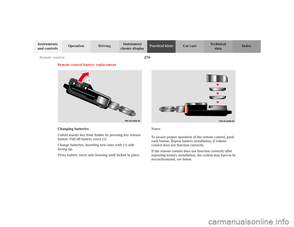
Changing batteries
Unfold master key from holder by pressing key release
button. Pull off battery cover (1).
Change batteries, inserting new ones with (+) side
facing up.
Press battery cover onto housing until locked in place. Notes:
To assure proper operation of the remote control, push
each button. Repeat battery installation, if remote
control does not function correctly.
If the remote control does not function correctly after
repeating battery installation, the system may have to be
resynchronized, see below.
Page 738 of 4133
271
Remote control
Te ch n ica l
data
Instruments
and controls Operation Driving
Instrument
cluster display Practical hints
Car care Index
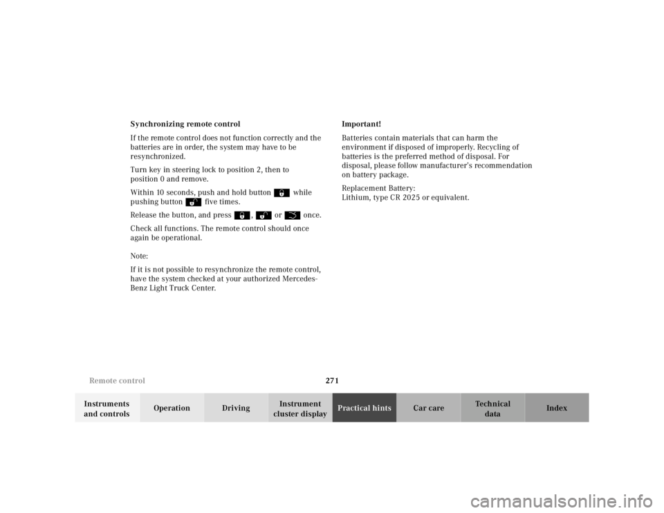
Synchronizing remote control
If the remote control does not function correctly and the
batteries are in order, the system may have to be
resynchronized.
Turn key in steering lock to position 2, then to
position 0 and remove.
Within 10 seconds, push and hold button ‹ while
pushing button Πfive times.
Release the button, and press ‹, Œ orŠ once.
Check all functions. The remote control should once
again be operational.
Note:
If it is not possible to resynchronize the remote control,
have the system checked at your authorized Mercedes-
Benz Light Truck Center. Important!
Batteries contain materials that can harm the
environment if disposed of improperly. Recycling of
batteries is the preferred method of disposal. For
disposal, please follow manufacturer’s recommendation
on battery package.
Replacement Battery:
Lithium, type CR 2025 or equivalent.
Page 767 of 4133
300
Index
Te ch n ica l
data
Instruments
and controls Operation Driving
Instrument
cluster display Practical hints Car care
Index
Index
AABS (Antilock brake system) ....................................... 201 LOW RANGE – ABS ..................................................202
Malfunction indicator lamp .....................................222
Adjustable steering wheel .............................................. 70 Indicator lamp ...........................................................222
Adjusting headlamp aim ...............................................268
Air conditioner refrigerant ...........................................294
Air pump .........................................................................239
Air recirculation ............................................................ 102
Airbag deactivation system ............................................ 53
Airbag OFF indicator lamp ...........................................222
Airbags .............................................................................. 56
Alarm system ............................................................. 35, 36
Anticorrosion/antifreeze .................... 181, 235, 293, 297
Antiglare night position ................................................. 71
Antilock brake system (ABS) ....................................... 201 LOW RANGE – ABS ..................................................202
Malfunction indicator lamp .....................................222
Antitheft alarm system ................................................... 35
Aquaplaning ................................................................... 178 Ashtray
Center console, front ................................................ 118
Rear passenger compartment ................................. 118
Automatic central locking ..............................................32
Automatic transmission ................................................ 165 Emergency Operation ............................................... 172
Fluid level .................................................................. 234
Selector lever position .............................................. 168
Transmission selector lever, manually unlocking 259
BBabySmart
TM airbag deactivation system ..................... 53
Self-test ......................................................................... 53
BAS (Brake assist system) ............................................ 199 Malfunction indicator lamp .....................................221
Battery .............................................................................251 Battery recycling ...................................................... 252
Charge indicator lamp ............................................. 223
Battery, remote control ................................................. 270
Block heater .................................................................... 182
Blocking of rear door windows ....................................105
Brake assist system (BAS) ............................................ 199 Malfunction indicator lamp .....................................221