tow MERCEDES-BENZ ML320 1997 Complete Service Manual
[x] Cancel search | Manufacturer: MERCEDES-BENZ, Model Year: 1997, Model line: ML320, Model: MERCEDES-BENZ ML320 1997Pages: 4133, PDF Size: 88.89 MB
Page 309 of 4133
259 Towing
Te ch n ica l
data Instruments
and controlsOperation DrivingInstrument
cluster displayPractical hintsCar care Index Transmission selector lever, manually unlocking
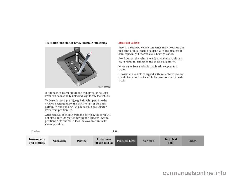
In the case of power failure the transmission selector
lever can be manually unlocked, e.g. to tow the vehicle.
To do so, insert a pin (1), e.g. ball point pen, into the
covered opening below the position “D” of the shift
pattern. While pushing the pin down, move selector
lever from position “P”.
After removal of the pin from the opening, the cover will
not close fully. Only after moving the selector lever to
positions “D+” and “D–” does the cover return to its
closed position.Stranded vehicle
Freeing a stranded vehicle, on which the wheels are dug
into sand or mud, should be done with the greatest of
care, especially if the vehicle is heavily loaded.
Avoid pulling the vehicle jerkily or diagonally, since it
could result in damage to the chassis alignment.
Never try to free a vehicle that is still coupled to a
trailer.
If possible, a vehicle equipped with trailer hitch receiver
should be pulled backward in its own previously made
tracks.
Page 316 of 4133
266 Exterior lamps
Te ch n ica l
data Instruments
and controlsOperation DrivingInstrument
cluster displayPractical hintsCar care Index
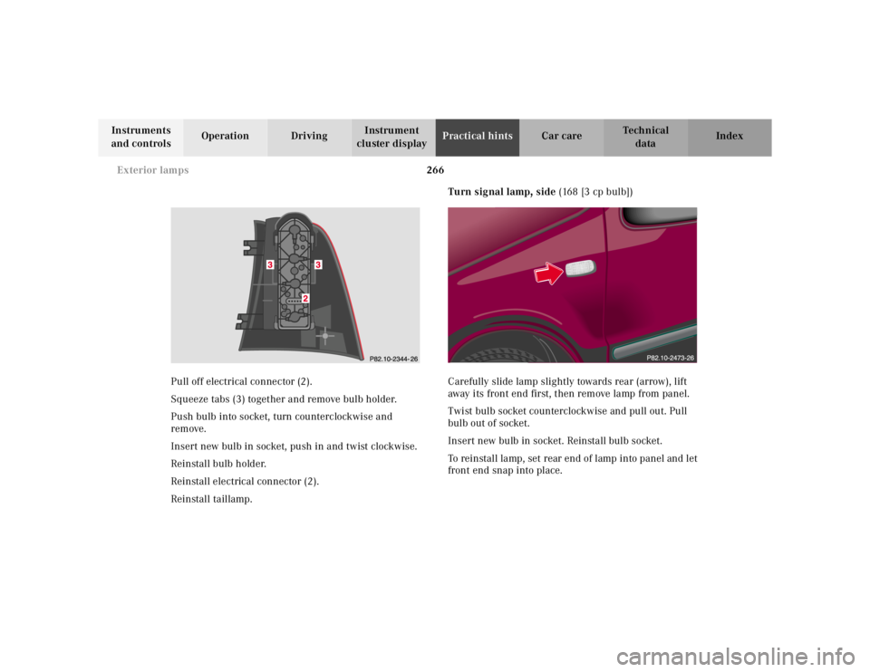
Pull off electrical connector (2).
Squeeze tabs (3) together and remove bulb holder.
Push bulb into socket, turn counterclockwise and
remove.
Insert new bulb in socket, push in and twist clockwise.
Reinstall bulb holder.
Reinstall electrical connector (2).
Reinstall taillamp.Turn signal lamp, side (168 [3 cp bulb])
Carefully slide lamp slightly towards rear (arrow), lift
away its front end first, then remove lamp from panel.
Twist bulb socket counterclockwise and pull out. Pull
bulb out of socket.
Insert new bulb in socket. Reinstall bulb socket.
To reinstall lamp, set rear end of lamp into panel and let
front end snap into place.
Page 330 of 4133
280 Cleaning and care of the vehicle
Te ch n ica l
data Instruments
and controlsOperation DrivingInstrument
cluster displayPractical hintsCar careIndex
Engine cleaning
Prior to cleaning the engine compartment make sure to
protect electrical components and connectors from the
intrusion of water and cleaning agents.
Corrosion protection, such as MB Anticorrosion Wax
should be applied to the engine compartment after
every engine cleaning. Before applying, all control
linkage bushings and joints should be lubricated. The
poly-V-belt and all pulleys should be protected from any
wax.
Ve h i c l e w a s h i n g
Do not use hot water or wash your vehicle in direct
sunlight. Use only a mild car wash detergent, such as
Mercedes-Benz approved Car Shampoo.
Thoroughly spray the vehicle with a diffused jet of
water. Direct only a very weak spray towards the
ventilation intake. Use plenty of water and rinse the
sponge and chamois frequently.
Rinse with clear water and thoroughly wipe dry with a
chamois. Do not allow cleaning agents to dry on the
finish.Due to the width of the vehicle, prior to running the
vehicle through an automatic car wash, fold back the
outside mirrors to prevent them from getting damaged.
In the winter, thoroughly remove all traces of road salt
as soon as possible.
When washing the underbody, do not forget to clean the
inner sides of the wheels.
Ornamental moldings
For regular cleaning and care of very dirty chrome-
plated parts, use a chrome cleaner.
Headlamps, taillamps, turn signal lenses
Use a mild car wash detergent, such as Mercedes-Benz
approved Car Shampoo, with plenty of water.
To prevent scratches, never apply strong force and use
only a soft, non-scratchy cloth when cleaning the lenses.
Do not attempt to wipe dirty lenses with a dry cloth or
sponge.
Page 359 of 4133
309 Index
Te ch n ica l
data Instruments
and controlsOperation DrivingInstrument
cluster displayPractical hints Car careIndex Special settings (Climate control) ............................... 101
Split rear seat bench ..................................................... 120
Easy entry/exit feature ............................................ 123
Rear seat head restraints ......................................... 124
SRS indicator lamp ........................................................ 219
SRS malfunction .............................................................. 57
Start lock-out .................................................................... 25
Starting and turning off the engine ............................ 164
Steering lock ................................................................... 162
Steering wheel
Adjustable .................................................................... 70
Indicator lamp ...........................................................222
Stop lamp, high mounted .............................................267
Storage compartments
Center console ............................................................115
Compartment under front passenger seat .............116
Glove box .....................................................................115
Stowing things in the vehicle ......................................230
Stranded vehicle ............................................................259
Sun visors ........................................................................113
Supplemental restraint system (SRS) ........................... 54
Synchronizing remote control ..................................... 271
TTachometer ........................................................................82
Technical data ................................................................ 287
Electrical system ...................................................... 290
Main dimensions ...................................................... 291
Rims and tires ..................................................288, 289
Weights ...................................................................... 290
Tele Aid ............................................................................ 148
Emergency calls ........................................................149
Information ................................................................ 154
Initiating an emergency call manually .................. 151
Roadside Assistance ................................................. 152
Telephone, general ......................................................... 139
Telephones and two-way radios ................................... 146
Telescoping steering column
Adjusting ......................................................................70
Indicator lamp .......................................................... 222
The first 1 000 miles (1 500 km) ................................147
Third row seats ...............................................................126
Tie-down rings, cargo .................................................... 132
Tire inflation pressure ................................................. 250
Tire traction ....................................................................178
Page 360 of 4133
310 Index
Te ch n ica l
data Instruments
and controlsOperation DrivingInstrument
cluster displayPractical hints Car careIndex
Tires
Driving instructions ................................................. 177
Rims and tires ...........................................................288
Rotating wheels ......................................................... 241
Tire inflation pressure .............................................250
Tire replacement .......................................................240
Winter driving instructions .................................... 180
Tow-away alarm ................................................................ 36
Switching off ................................................................ 36
Towing the vehicle .........................................................255
Stranded vehicle .......................................................259
Transmission selector lever, manually unlocking 259
Trailer operation ............................................................ 198
Trailer towing ................................................................. 190
Transmission .................................................................. 165
Transmission control - LOW RANGE mode ...............209
Transmission fluid level ...............................................234
Transmission selector lever, manually unlocking ....259
Traveling abroad ............................................................ 182
Trip computer ................................................................... 83
Trip odometer ................................................................... 80
Trunk ................................................................................. 34
Opening ........................................................................ 28
Trunk lamp ...................................................................... 111Turn signal failure ........................................................... 91
Turn signal lamp, side .................................................. 266
Turn signals ......................................................................90
UUnlocking the vehicle ...................................................... 27VVanity mirrors ................................................................ 113
Vehicle jack .................................................................... 237
Vehicle keys ......................................................................24
Ve h i c l e t o o l s
Screwdriver ............................................................... 237WWarranty coverage ........................................................ 284
Washing the vehicle ..................................................... 280
What you should know at the gas station .................. 212
Wheel bolt wrench ........................................................ 237
Wheels ............................................................................ 240
Changing wheels ...................................................... 245
Page 370 of 4133
assembly. To install, reverse removal pr ocedure. Activate air bag system. See DISABLING &
ACTIVATING AIR BAG SYSTEM . Perform system operation check to ensure system is functioning
properly. See SYSTEM OPERATION CHECK
.
CONTROL MODULE
Removal & Installation (C Class)
1. Before proceeding, See AIR BAG SAFETY PRECAUTIONS . Disable air bag system. See
DISABLING & ACTIVATI NG AIR BAG SYSTEM
. Remove ignition key. Remove shift lever cover
bezel. Lift shift lever cover e nough to disconnect electrical connector . Remove shift lever cover.
2. Remove storage compartment mount ing screws from center console. Remove storage compartment.
Remove ashtray. Disconnect electrical connectors as necessary. Disconnect SRS control module electrical
connector. Remove SRS contro l module mounting bolts. Remove SRS control module.
3. To install, reverse removal proce dure. Ensure SRS control module arro w points to front of vehicle. Set
parameters and program new SRS control module wi th Hand-Held Tester (965 589 00 01 00). Activate
air bag system. Perform system operation check to ensure system is functioning properly. See SYSTEM
OPERATION CHECK .
Removal & Installation (E Class)
1. Before proceeding, See AIR BAG SAFETY PRECAUTIONS . Disable air bag system. See
DISABLING & ACTIVATI NG AIR BAG SYSTEM
. Remove ignition key. Remove gear shift cover
panel. Remove ashtray and ashtray housing at front of console. Remove radio (if necessary).
2. Remove center console right side cover screws and ri ght side cover. Disconnect electrical connector for
control module. Remove 2 control module m ounting screws. Remove control module.
3. To install, reverse removal proce dure. Ensure SRS control module arro w points to front of vehicle. Set
parameters and program new SRS control module wi th Hand-Held Tester (965 589 00 01 00). Activate
air bag system. Perform system operation check to ensure system is functioning properly. See SYSTEM
OPERATION CHECK .
Removal & Installation (S Class)
1. Before proceeding, See AIR BAG SAFETY PRECAUTIONS . Disable air bag system. See
DISABLING & ACTIVATI NG AIR BAG SYSTEM
. Remove ignition key. Remove radio. Remove
ashtray. Remove wooden surround for ashtray. Remove shift lever cover mounting screws. Push shift
lever cover toward rear of vehicle and remove in an upward direction.
2. Remove center console cover screws. Remove cente r console cover by pulling from bottom in an upward
direction. When removing covers, di sconnect electrical connectors as necessary. Disconnect SRS control
module electrical connector. Re move SRS control module.
3. To install, reverse removal proce dure. Ensure SRS control module arro w points to front of vehicle. Set
parameters and program new SRS control module wi th Hand-Held Tester (965 589 00 01 00). Activate
air bag system. Perform system operation check to ensure system is functioning properly. See SYSTEM
OPERATION CHECK .
Removal & Installation (SL Class)
2001 Mercedes-Benz ML320
2000-01 ACCESSORIES/SAFETY EQUIPMENT Merc edes-Benz - Air Bag Restraint Systems
me
Saturday, October 02, 2010 3:44:45 PMPage 6 © 2006 Mitchell Repair Information Company, LLC.
Page 374 of 4133
Fig. 2: Removing Side Air Bag Unit (2000 Models)
Courtesy of MERCEDES-BENZ OF NORTH AMERICA.
SIDE AIR BAG SENSOR (DRIVER-SIDE & PASSENGER-SIDE)
Removal & Installation
1. Before proceeding, See AIR BAG SAFETY PRECAUTIONS . Disable air bag system. See
DISABLING & ACTIVATI NG AIR BAG SYSTEM
. Remove ignition key. On SLK 230, remove
door sill moulding. On all models, re move front seat. Fold floor covering in area toward rear. Unclip
connector on side bag sensor. Remove 2 mounting screws. Rem ove sensor from vehicle.
2. To install, reverse removal proce dure. Ensure that arrow on sensor poi nts toward outside. Perform system
operation check to ensure system is functioning properly. See SYSTEM OPERATION CHECK
.
2001 Mercedes-Benz ML320
2000-01 ACCESSORIES/SAFETY EQUIPMENT Merc edes-Benz - Air Bag Restraint Systems
me
Saturday, October 02, 2010 3:44:45 PMPage 10 © 2006 Mitchell Repair Information Company, LLC.
Page 379 of 4133
module.
2. To install air bag module, reverse removal procedur e. Activate air bag system. Perform system operation
check to ensure system is functioning properly. See SYSTEM OPERATION CHECK
.
Removal & Installation (SLK 320)
1. Before proceeding, See AIR BAG SAFETY PRECAUTIONS . Disable air bag system. See
DISABLING & ACTIVATI NG AIR BAG SYSTEM
. Remove ignition key. Remove top section of
instrument panel. Fold vapor barrier toward front to reveal 2 screws. Disconnect passenger-side air bag
module connector. Remove 4 screws and passenger-side air bag module.
2. To install air bag module, reverse removal procedur e. Activate air bag system. Perform system operation
check to ensure system is functioning properly. See SYSTEM OPERATION CHECK
.
DIAGNOSTICS
Before proceeding, see AIR BAG SAFETY PRECAUTIONS
. The SRS control module is capable of
diagnosing air bag system components and ETR components. If a fault is detected by the SRS control module
or system is malfunctioning, SRS warning light will do one or more of the following:
SRS warning light goes out after 2 minutes. System fault is noted, however occupant protection is not
affected. See RETRIEVING FAULT CODES
.
SRS warning light illuminates cont inuously. System is faulty which may result in a non deployment or
false deployment. See RETRIEVING FAULT CODES
.
SRS warning light blinks continuous ly. Control module has been replaced without setting control module
parameters.
RETRIEVING FAULT CODES
1. Check vehicle fuses. Replace any blown fuses as nece ssary. Ensure vehicle battery voltage is 11 volts or
more. Ensure SRS warning light functions. Turn i gnition off. Connect Hand-Held Tester (HHT) (965 589
00 01) to Data Link Connector (DLC).
2. DLC is located in right rear corner of engine comp artment. It may be necessary to use Adapter (965 589
00 40 or 965 589 00 50) to connect HHT to DLC. Afte r HHT displays module number and version, press
return key to start diagnosis. Us ing HHT, follow HHT prompts to re trieve SRS fault codes. For SRS
control modules beginning with number 000, fault c ode 1 is valid. For SRS control modules beginning
with number 001, fault code 2 is valid. See Fig. 6
.
3. HHT will display a 3 digit fault code, and may display additional graphic information. This additional
graphic information will help in diagnosis of fault code. See Fig. 5
. During diagnosis HHT will display 4
different graphic displays info rming technician if a test passes or fail s, or if seat belt buckle is latched or
NOTE: After component replacement, perf
orm a system operation check to ensure
proper system operation. S ee SYSTEM OPERATION CHECK
.
NOTE: Fault codes may only be retrieved us ing Hand-Held Tester (965 589 00 01) and
Adapter (965 589 00 40 or 965 589 00 50).
2001 Mercedes-Benz ML320
2000-01 ACCESSORIES/SAFETY EQUIPMENT Merc edes-Benz - Air Bag Restraint Systems
me
Saturday, October 02, 2010 3:44:45 PMPage 15 © 2006 Mitchell Repair Information Company, LLC.
Page 468 of 4133

1
Contents
IntroductionProduct information .......................... 7
Roadside assistance ......................... 10
Where to find it ................................ 14
Reporting Safety Defects ................ 16Instruments and controlsInstruments and controls ............... 18 Center console .............................. 20
Overhead control panel ............... 21OperationVehicle keys ...................................... 24
Start lock-out .................................... 25
General notes on the central locking system ............... 26
Central locking system ................... 26 Radio frequency
remote control .............................. 26
Unlocking the liftgate .................. 28
Panic button .................................. 28
Mechanical keys ........................... 29 Doors ................................................. 30
Central locking switch .................... 32 Automatic central locking .......... 32
Emergency unlocking in case of accident ................................... 33
Liftgate .............................................. 34
Antitheft alarm system ................... 35
Tow-away alarm and glass breakage sensor ............... 36
Seats, front ....................................... 37
Manual seats ................................ 39
Power seats ................................... 40
Head restraint ...............................41
Heated seats ..................................... 44
Seat belts and integrated restraint system .......................... 46
Seat belts .......................................... 46 Seat belt nonusage
warning system ............................ 47
BabySmart
TM airbag
deactivation system ................... 53
Self-test BabySmart
TM
without special child
seat installed ................................ 53 Supplemental restraint
system (SRS) ................................ 54
Emergency tensioning retractor (ETR) ............................. 55
Airbags .............................................. 56 Safety guidelines for the
seat belt, emergency
tensioning retractor
and airbag ..................................... 63
Infant and child
restraint systems .......................... 65
Adjustable steering wheel .............. 70
Inside rear view mirror .................. 71 Antiglare night position .............. 71
Exterior rear view mirrors ............. 73 Exterior rear view mirror,
electrically folding ....................... 75
Instrument cluster ........................... 76
Indicator lamps in the instrument cluster ...................... 78
Trip computer ................................... 83
Flexible service system (FSS) ........ 87
Engine oil level indicator ................ 89
Exterior lamp switch ....................... 90
Page 470 of 4133

3
Contents Snow chains ................................ 179
Winter driving instructions ...... 180
Deep water .................................. 181
Passenger compartment ........... 182
Traveling abroad ........................ 182
Off-Road driving ............................. 183
Trailer towing ................................. 190
Cruise control ................................. 196
Brake assist system (BAS) ............ 199
Antilock brake system (ABS) ....... 201
Four-wheel electronic traction system (4-ETS+) ..........203
Electronic brake proportioning (EBP) ..................204
Electronic stability program (ESP) ...........................................205
Transmission control – LOW RANGE mode ...................209
What you should know at the gas station ....................... 212
Check regularly and before a long trip ....................... 215
Instrument cluster displayMalfunction and indicator lamps in the
instrument cluster .....................218
On-board diagnostic system –
Check engine malfunction
indicator lamp .............................218
Brake warning lamp ...................219
Supplemental restraint system
(SRS) indicator lamp .................. 219
Fuel reserve warning ................ 220
Electronic stability
program (ESP) / Electronic
traction system (ETS) –
warning lamp ............................. 221
BAS/ESP malfunction
indicator lamp ............................ 221
4-ETS malfunction
indicator lamp ............................ 221
LOW RANGE
indicator lamp ............................ 221
ABS malfunction
indicator lamp ............................ 222 Adjustable steering wheel –
indicator lamp .............................222
AIRBAG OFF
indicator lamp .............................222
Seat belt warning lamp .............223
Charge indicator lamp ...............223
Low engine oil level
warning lamp ..............................224
Low engine coolant
level warning ..............................224
Brake pad wear
indicator lamp .............................225
FSS indicator ...............................225