hood open MERCEDES-BENZ ML320 1997 Complete Manual PDF
[x] Cancel search | Manufacturer: MERCEDES-BENZ, Model Year: 1997, Model line: ML320, Model: MERCEDES-BENZ ML320 1997Pages: 4133, PDF Size: 88.89 MB
Page 3208 of 4133
AR88.40-P-3200GH
Removing and installing engine hood lock
8.4.99
MODEL
163.136 /154 /172 up to 31.8.99
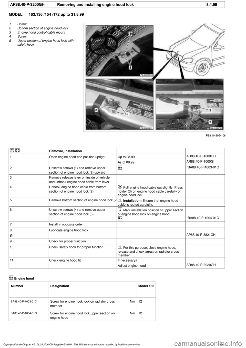
P88.40-2054-06
1
Screw
2
Bottom section of engine hood lock
3
Engine hood control cable mount
4
Screw
5
Upper section of engine hood lock with
safety hook
Removal, installation
1
Open engine hood and position upright
Up to 08.99
AR88.40-P-1000GH
As of 09.99
AR88.40-P-1000GI
2
Unscrew screws (1) and remove upper
section of engine hood lock (2) upward
*BA88.40-P-1003-01C
3
Remove release lever on inside of vehicle
and unhook engine hood cable from lever
4
Unhook engine hood cable from bottom
section of engine hood lock (2)
Pull engine hood cable out slightly. Press
holder (3) on engine hood cable carefully off
engine hood lock.
5
Remove bottom section of engine hood lock (2)
Installation:
Ensure that engine hood
cable is routed carefully.
6
Unscrew screws (4) and remove upper
section of engine hood lock (5)
Mark installation position of upper section
of engine hood lock on engine hood.
*BA88.40-P-1004-01C
7
Install in opposite order
8
Lubricate engine hood lock
e
AP88.40-P-8821GH
9
Check for proper function
10
Check safety hook for proper function
For this purpose, close engine hood,
release and check arrest on radiator cross
member
11
Check engine hood fit
If necessary
#
Adjust engine hood
AR88.40-P-3020GH
Engine hood
Number
Designation
Model 163
BA88.40-P-1003-01C
Screw for engine hook lock on radiator cross
member
Nm
12
BA88.40-P-1004-01C
Screw for engine hood lock upper section on
engine hood
Nm
12
Copyright DaimlerChrysler AG 09.05.2006 CD-Ausgabe G/10/04 . This WIS print-out will not be recorde
d by Modification services.
Page 1
Page 3209 of 4133
AR88.40-P-3000GH
Remove/install engine hood
25.3.97
MODEL
163.113 /128 /136 /154 /157 /172 /174 /175
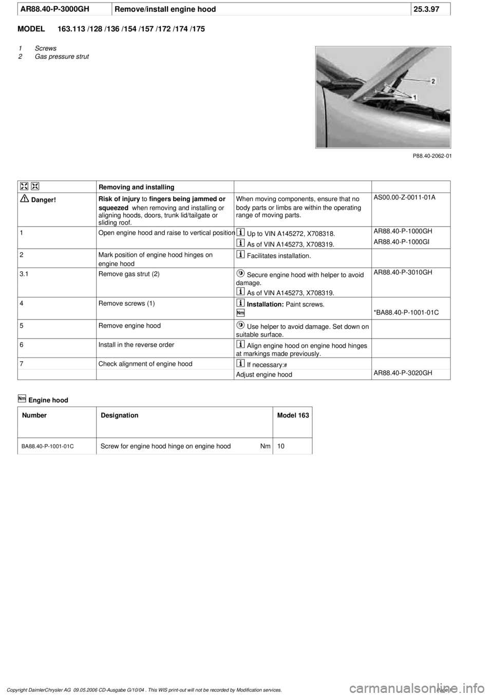
P88.40-2062-01
1
Screws
2
Gas pressure strut
Removing and installing
Danger!
Risk of injury
to
fingers being jammed or
squeezed
when removing and installing or
aligning hoods, doors, trunk lid/tailgate or
sliding roof.
When moving components, ensure that no
body parts or limbs are within the operating
range of moving parts.
AS00.00-Z-0011-01A
1
Open engine hood and raise to vertical position
Up to VIN A145272, X708318.
AR88.40-P-1000GH
As of VIN A145273, X708319.
AR88.40-P-1000GI
2
Mark position of engine hood hinges on
engine hood
Facilitates installation.
3.1
Remove gas strut (2)
Secure engine hood with helper to avoid
damage.
AR88.40-P-3010GH
As of VIN A145273, X708319.
4
Remove screws (1)
Installation:
Paint screws.
*BA88.40-P-1001-01C
5
Remove engine hood
Use helper to avoid damage. Set down on
suitable surface.
6
Install in the reverse order
Align engine hood on engine hood hinges
at markings made previously.
7
Check alignment of engine hood
If necessary:
#
Adjust engine hood
AR88.40-P-3020GH
Engine hood
Number
Designation
Model 163
BA88.40-P-1001-01C
Screw for engine hood hinge on engine hood
Nm
10
Copyright DaimlerChrysler AG 09.05.2006 CD-Ausgabe G/10/04 . This WIS print-out will not be recorde
d by Modification services.
Page 1
Page 3211 of 4133
AR88.40-P-3010GH
Remove/install gas-operated strut on engine hood
6.4.99
MODEL
163.136 /154 /172 #A as of 145273,
163.136 /154 /172 #X as of 708319,
163.113 /128 /157 /174 /175
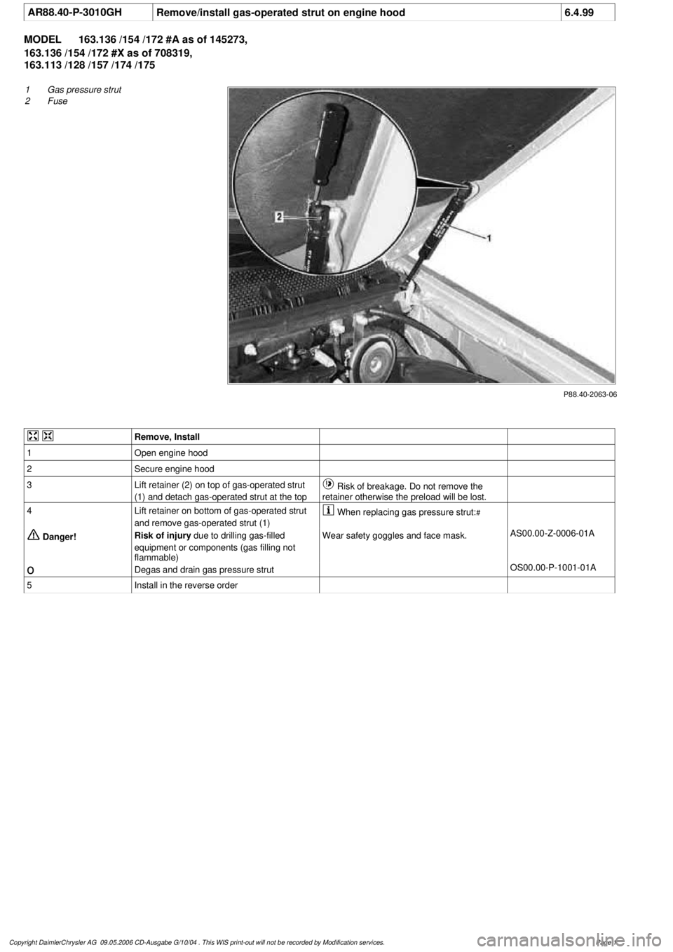
P88.40-2063-06
1
Gas pressure strut
2
Fuse
Remove, Install
1
Open engine hood
2
Secure engine hood
3
Lift retainer (2) on top of gas-operated strut
(1) and detach gas-operated strut at the top
Risk of breakage. Do not remove the
retainer otherwise the preload will be lost.
4
Lift retainer on bottom of gas-operated strut
and remove gas-operated strut (1)
When replacing gas pressure strut:
#
Danger!
Risk of injury
due to drilling gas-filled
equipment or components (gas filling not
flammable)
Wear safety goggles and face mask.
AS00.00-Z-0006-01A
o
Degas and drain gas pressure strut
OS00.00-P-1001-01A
5
Install in the reverse order
Copyright DaimlerChrysler AG 09.05.2006 CD-Ausgabe G/10/04 . This WIS print-out will not be recorde
d by Modification services.
Page 1
Page 3236 of 4133
Fig. 9: Replacing Intake Air Dust Filter
Courtesy of MERCEDES-BENZ OF NORTH AMERICA.
RECEIVER-DRIER
Removal & Installation
1. Discharge A/C system, using approved refrigerant recovery/recycling equipment. Remove headlight
units. Remove headlight units. Remove upper frame crossmember, release hood release control cable and
remove crossmember. See Fig. 6
.
2. Remove bolts from receiver-drier refrigerant lines. See Fig. 5
. Disconnect refrigerant lines from receiver-
drier. Plug exposed openings to protect A/C system from debris and moisture. Discard "O" rings. Loosen
receiver-drier clamp bolt. Remove receiver-drier. To install, reverse removal procedure.
3. When installing a new receiver-drier, add 0.34 ounce of NEW refrigerant oil to receiver-drier. Use NEW
"O" rings. Tighten refrigerant line bolts to specification. See TORQUE SPECIFICATIONS
.
TORQUE SPECIFICATIONS
TORQUE SPECIFICATIONS
WIRING DIAGRAMS
ApplicationFt. Lbs. (N.m)
Compressor Mounting Bolts15 (20)
Refrigerant Line-To-Compressor Bolt15 (20)
Refrigerant Line-To-Condenser Bolt15 (20)
Steering Column Bolt15 (20)
Steering Column Nut13 (18)
INCH Lbs. (N.m)
Expansion Valve Self-Locking Nut89 (10)
Refrigerant Line-To-Receiver-Drier Bolt89 (10)
2001 Mercedes-Benz ML320
2000-01 MANUAL A/C-HEATER SYSTEMS ML 320, ML 430 & ML 55
me
Saturday, October 02, 2010 3:25:10 PMPage 25 © 2006 Mitchell Repair Information Company, LLC.
Page 3752 of 4133
AR46.20-P-0600GH
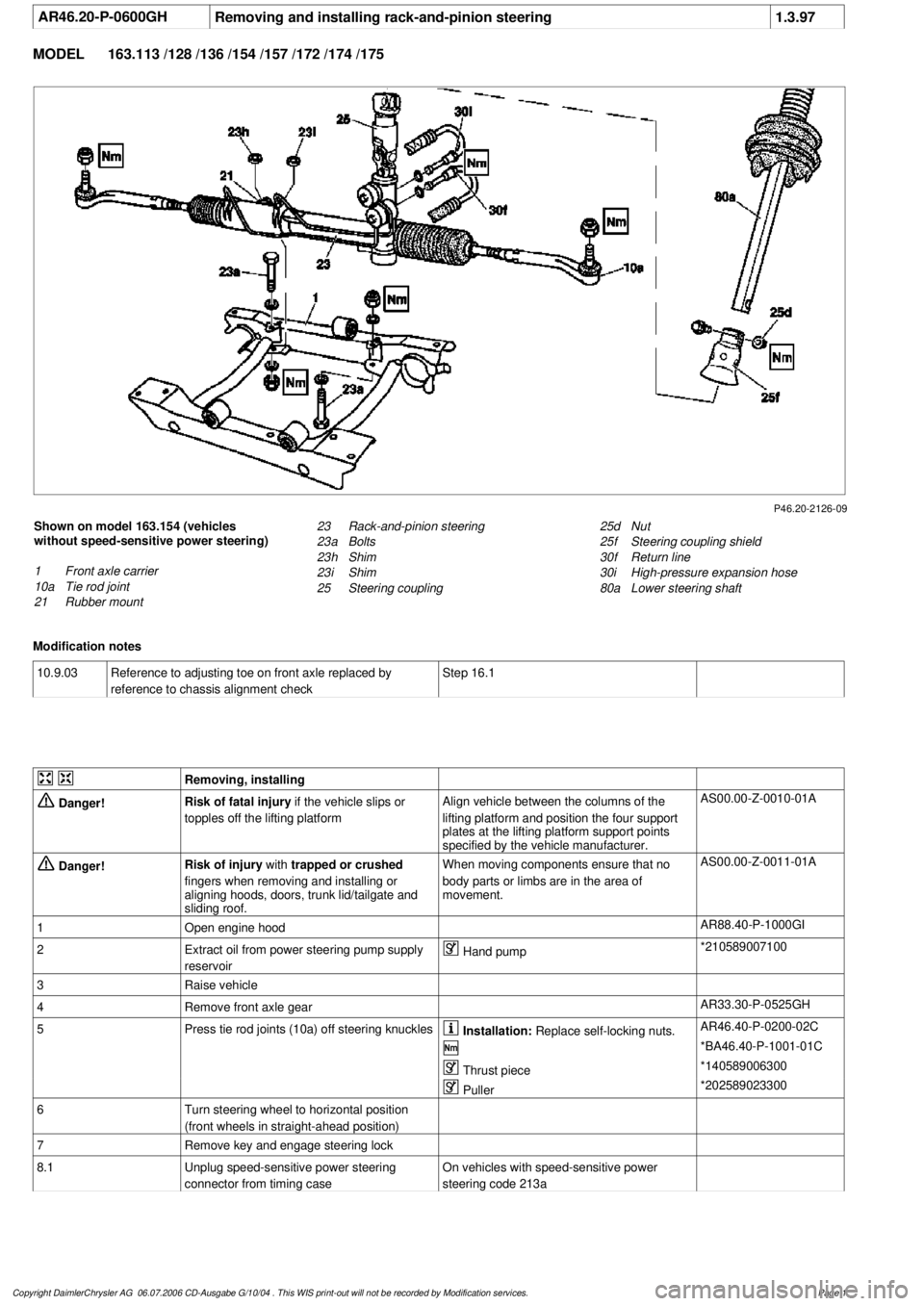
Removing and installing rack-and-pinion steering
1.3.97
MODEL
163.113 /128 /136 /154 /157 /172 /174 /175
P46.20-2126-09
Shown on model 163.154 (vehicles
without speed-sensitive power steering)
1
Front axle carrier
10a
Tie rod joint
21
Rubber mount
25d
Nut
25f
Steering coupling shield
30f
Return line
30i
High-pressure expansion hose
80a
Lower steering shaft
23
Rack-and-pinion steering
23a
Bolts
23h
Shim
23i
Shim
25
Steering coupling
Modification notes
10.9.03
Reference to adjusting toe on front axle replaced by
reference to chassis alignment check
Step 16.1
Removing, installing
Danger!
Risk of fatal injury
if the vehicle slips or
topples off the lifting platform
Align vehicle between the columns of the
lifting platform and position the four support
plates
at the lifting platform support points
specified by the vehicle manufacturer.
AS00.00-Z-0010-01A
Danger!
Risk of injury
with
trapped or crushed
fingers when removing and installing or
aligning hoods, doors, trunk lid/tailgate and
sliding roof.
When moving components ensure that no
body parts or limbs are in the area of
movement.
AS00.00-Z-0011-01A
1
Open engine hood
AR88.40-P-1000GI
2
Extract oil from power steering pump supply
reservoir
Hand pump
*210589007100
3
Raise vehicle
4
Remove front axle gear
AR33.30-P-0525GH
5
Press tie rod joints (10a) off steering knuckles
Installation:
Replace self-locking nuts.
AR46.40-P-0200-02C
*BA46.40-P-1001-01C
Thrust piece
*140589006300
Puller
*202589023300
6
Turn steering wheel to horizontal position
(front wheels in straight-ahead position)
7
Remove key and engage steering lock
8.1
Unplug speed-sensitive power steering
connector from timing case
On vehicles with speed-sensitive power
steering code 213a
Copyright DaimlerChrysler AG 06.07.2006 CD-Ausgabe G/10/04 . This WIS print-out will not be recorde
d by Modification services.
Page 1
Page 3759 of 4133
AR20.40-P-5000M
Remove/install electric fan
24.8.99
ENGINE
612.963 in MODEL 163.113
P20.40-2015-06
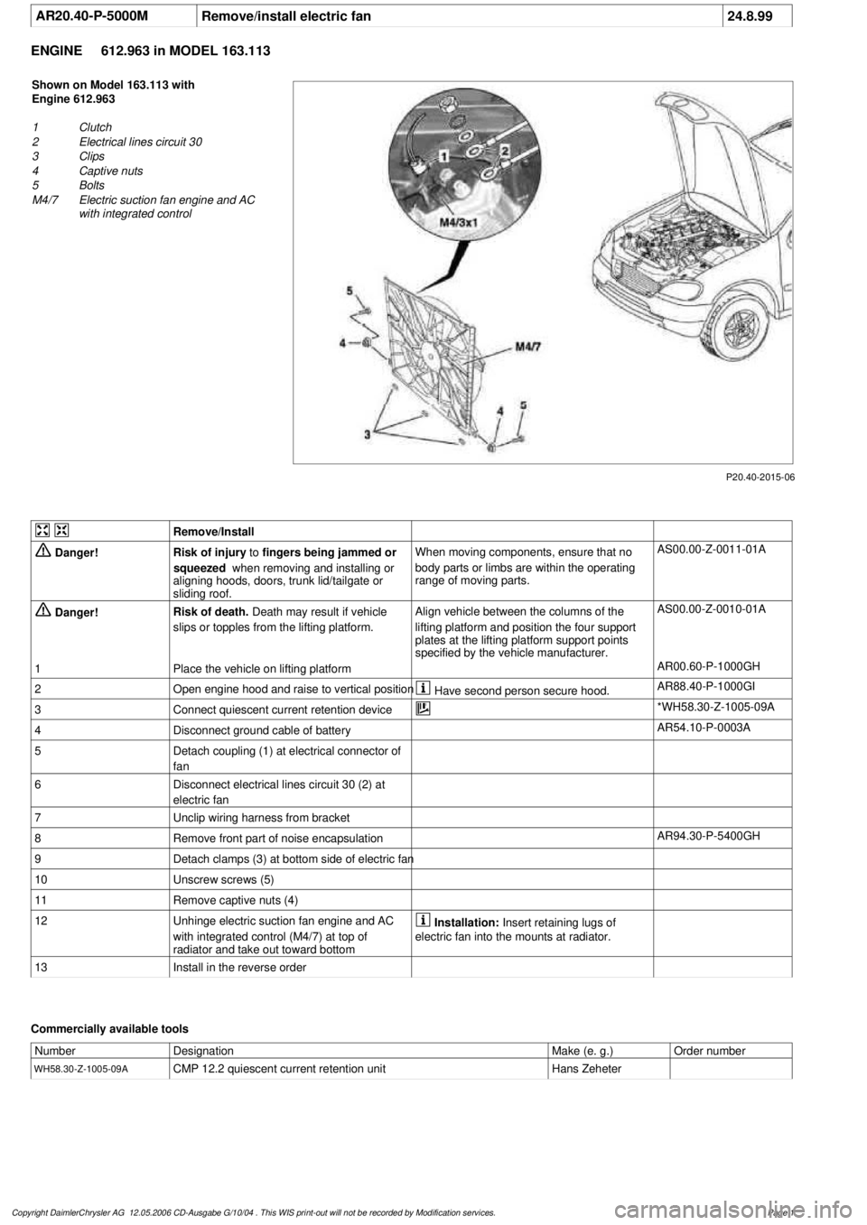
Shown on Model 163.113 with
Engine 612.963
1
Clutch
2
Electrical lines circuit 30
3
Clips
4
Captive nuts
5
Bolts
M4/7
Electric suction fan engine and AC
with integrated control
Remove/Install
Danger!
Risk of injury
to
fingers being jammed or
squeezed
when removing and installing or
aligning hoods, doors, trunk lid/tailgate or
sliding roof.
When moving components, ensure that no
body parts or limbs are within the operating
range of moving parts.
AS00.00-Z-0011-01A
Danger!
Risk of death.
Death may result if vehicle
slips or topples from the lifting platform.
Align vehicle between the columns of the
lifting platform and position the four support
plates
at the lifting platform support points
specified by the vehicle manufacturer.
AS00.00-Z-0010-01A
1
Place the vehicle on lifting platform
AR00.60-P-1000GH
2
Open engine hood and raise to vertical position
Have second person secure hood.
AR88.40-P-1000GI
3
Connect quiescent current retention device
*WH58.30-Z-1005-09A
4
Disconnect ground cable of battery
AR54.10-P-0003A
5
Detach coupling (1) at electrical connector of
fan
6
Disconnect electrical lines circuit 30 (2) at
electric fan
7
Unclip wiring harness from bracket
8
Remove front part of noise encapsulation
AR94.30-P-5400GH
9
Detach clamps (3) at bottom side of electric fan
10
Unscrew screws (5)
11
Remove captive nuts (4)
12
Unhinge electric suction fan engine and AC
with integrated control (M4/7) at top of
radiator and take out toward bottom
Installation:
Insert retaining lugs of
electric fan into the mounts at radiator.
13
Install in the reverse order
Commercially available tools
Number
Designation
Make (e. g.)
Order number
WH58.30-Z-1005-09A
CMP 12.2 quiescent current retention unit
Hans Zeheter
Copyright DaimlerChrysler AG 12.05.2006 CD-Ausgabe G/10/04 . This WIS print-out will not be recorde
d by Modification services.
Page 1
Page 3761 of 4133

Danger!
Risk of injury
to skin and eyes suffering
scalding from contact with hot coolant spray.
Risk of poisoning
from swallowing coolant.
Do not open cooling system unless coolant
temperature is below 90 °C. Open cap slowly
and release the pressure. Do not pour coolant
into beverage bottles.
Wear protective gloves, protective clothing
and eye protection.
AS20.00-Z-0001-01A
1
Open engine hood and raise to vertical position
Have second person secure hood.
AR88.40-P-1000GI
2
Connect no load current retention unit
*WH58.30-Z-1005-09A
3
Disconnect battery ground cable
AR54.10-P-0003A
4
Remove trim panel of cylinder head cover
AR01.20-P-5014-02B
*BA01.20-P-1002-01A
*BA01.20-P-1003-01A
5
Remove bottom part of noise encapsulation
at front
AR94.30-P-5400GH
6
Remove electric fan (1)
Remove toward bottom.
AR20.40-P-5000M
7
Drain coolant
At radiator.
AR20.00-P-1142M
Notes on coolant
All engines
AH20.00-N-2080-01A
8
Remove charge air cooler (110/2)
AR09.41-P-6817MM
9.1
Attach guard plate for radiator/condenser
With automatic air conditioning, code
581a and AC system or Tempmatic USA,
code 580.
Attach additional AC condenser in the
vehicle.
y
Guard plate for radiator/condenser
Engine 606 in model 124,
Engine 606.961 in model 140,
Engine 112, 113, 604, 605, 611.960 in
MODEL 202,
Engine 602.983, 612.966 in MODEL 461,
Engine 628.962, 612.965, 606.964, 112.945,
113.962/ 982 in MODEL 463,
Engine 111, 112, 611.962, 612.962 in model
203,
Engines 112, 113, 611.961, 612.961, 613.961
in MODEL 210,
Engine 112 in model 170,
Engine 112 in MODEL 220,
Engine 113 in MODEL 211, 215, 220,
Engine 112 in MODEL 208,
Engine 112, 612.963, 628.963 in MODEL 163,
Engine 112.923 /943, 113.961 in MODEL 129,
Engine 137, 275 in MODEL 215, 220,
Engine 613.960, 628.960 in MODEL 220,
Engine 113.992 in model 230.474,
Engine 271 in model 209, 203,
Engine 285.950 in model 240.078 /178,
Engine 612.967 in model 209.316,
Engine 648 in model 220
Engine 112.951 in model 639.601/603/
605/701/703/705/801/803/805
Engine 646.983/984 in model 639.601/
603/605/701/703/705/801/803/805
Engine 646.982 in model
639.601/603/605/701/703/705
WF58.50-P-0110-01A
10
Remove seal rail (11)
11
Extract steering oil from reservoir
Hand pump
*210589007100
12.1
Disconnect power steering oil line (return line
radiator
!
power steering pump supply
reservoir) (18)
Seal connections.
Installation:
Install new sealing rings.
*BA46.30-P-1012-01A
Clamp
*000589543700
Set of stop plugs
*129589009100
12.2
Disconnect power steering oil line (feed line of
steering gear
!
radiator) (19)
Clamp
*000589543700
Set of stop plugs
*129589009100
Hexagon socket wrench
*WH58.30-Z-1001-06A
Hexagon socket wrench
*WH58.30-Z-1002-06A
Copyright DaimlerChrysler AG 12.05.2006 CD-Ausgabe G/10/04 . This WIS print-out will not be recorde
d by Modification services.
Page 2
Page 3771 of 4133
AR20.00-P-1250B
Remove oil from cooling and heating system
22.7.97
ENGINE
611.960 in MODEL 202.134 /193 /194 /133
ENGINE
611.961 in MODEL 210.006 /206 /007 /606
ENGINE
611.962 in MODEL 203.006 /004 /206 /204 /706
ENGINE
612.961 in MODEL 210.616 /216 /016
ENGINE
612.962 in MODEL 203.016 /216
ENGINE
612.963 in MODEL 163.113
ENGINE
613.960 in MODEL 220.026
ENGINE
613.961 in MODEL 210.026 /226
ENGINE
628.960 in MODEL 220.028 /128
ENGINE
628.961 in MODEL 211.028
ENGINE
628.963 in MODEL 163.128
ENGINE
646.951 in MODEL 211.004
ENGINE
646.961 in MODEL 211.006 /206 /606
ENGINE
647.961 in MODEL 211.016 /216 /616
ENGINE
648.961 in MODEL 211.023 /026 /223 /226
ENGINE
612.967 in MODEL 209.316
ENGINE
612.990 in MODEL 203.018 /218 /718
ENGINE
646.962 in MODEL 203.007 /207 /707
ENGINE
646.963 in MODEL 203.008 /208 /708
P20.00-2078-06
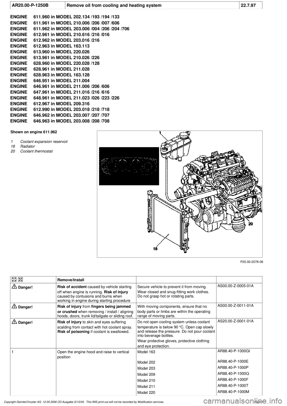
Shown on engine 611.962
1
Coolant expansion reservoir
18
Radiator
20
Coolant thermostat
Remove/Install
Danger!
Risk of accident
caused by vehicle starting
off when engine is running.
Risk of injury
caused by contusions and burns when
working in engine during starting procedure
Secure vehicle to prevent it from moving.
Wear closed and snug-fitting work clothes.
Do not grasp hot or rotating parts.
AS00.00-Z-0005-01A
Danger!
Risk of injury
from
fingers being jammed
or crushed
when removing / install / aligning
hoods, doors, trunk lid/tailgate or sliding roof.
With moving components, ensure that no
body parts or limbs are within the operating
range of moving parts.
AS00.00-Z-0011-01A
Danger!
Risk of injury
to skin and eyes suffering
scalding from contact with hot coolant spray.
Risk of poisoning
if coolant is swallowed.
Do not open cooling system unless coolant
temperature is below 90 °C. Open cap slowly
and release the pressure. Do not pour coolant
into beverage bottles.
Wear protective gloves, protective clothing
and eye protection.
AS20.00-Z-0001-01A
1
Open the engine hood and raise to vertical
position
Model 163
AR88.40-P-1000GI
Model 202
AR88.40-P-1000E
Model 203
AR88.40-P-1000P
Model 209
AR88.40-P-1000Q
Model 210
AR88.40-P-1000F
Model 211
AR88.40-P-1000T
Model 220
AR88.40-P-1000M
Copyright DaimlerChrysler AG 12.05.2006 CD-Ausgabe G/10/04 . This WIS print-out will not be recorde
d by Modification services.
Page 1
Page 3884 of 4133
Verify ground connection integrity between engine, body, battery and generator. Check for damaged wiring
harnesses and/or switches. Check fo r a broken or partially broken wire inside insulation, which could cause
system malfunction but prove good in a continuity/vol tage check with system disconnected. Ensure any
aftermarket electronic e quipment is properly installed. If fault is found, repair as necessary. If no fault is found,
check for conditions that might cause an intermittent situation.
SERVICE PRECAUTIONS
BATTERY DISCONNECT/CONNECT
Disconnect/Connect Procedures
1. Turn ignition off. Open engine hood. After opening ve hicle wait at least 4 minutes before disconnecting
battery or alarm wi ll be triggered.
2. Disconnect negative battery cable (1) and insulate cable lug to prevent unwanted contact with ground
point (W16/4). See Fig. 1
.
3. To connect, reverse disconnect procedur e. Tighten nut (5) to specification. See TORQUE
SPECIFICATIONS .
4. Perform basic programming, read Diagnostic Tr ouble Code (DTC) memory and erase DTCs from
memory. See BASIC PROGRAMMING
and RETRIEVING & ERASING DIAGNOSTIC
TROUBLE CODES .
NOTE: Numbers and letters in text refe
r to numbers and letters in figures.
2001 Mercedes-Benz ML320
2001-04 STARTING & CHARGING SYSTEMS Starters - 163 Chassis
me
Saturday, October 02, 2010 3:19:47 PMPage 2 © 2006 Mitchell Repair Information Company, LLC.