maintenance MERCEDES-BENZ ML320 1997 Complete Manual PDF
[x] Cancel search | Manufacturer: MERCEDES-BENZ, Model Year: 1997, Model line: ML320, Model: MERCEDES-BENZ ML320 1997Pages: 4133, PDF Size: 88.89 MB
Page 3876 of 4133

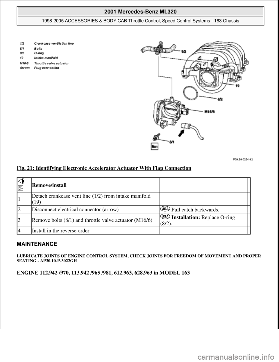
Fig. 21: Identifying Electronic Accelerator Actuator With Flap Connection
MAINTENANCE
LUBRICATE JOINTS OF ENGINE CONTROL SYSTEM, CHECK JOINTS FOR FREEDOM OF MOVEMENT AND PROPER
SEATING - AP30.10-P-3022GH
ENGINE 112.942 /970, 113.942 /965 /981, 612.963, 628.963 in MODEL 163
Remove/install
1Detach crankcase vent line (1/2) from intake manifold
(19)
2Disconnect electrical connector (arrow) Pull catch backwards.
3Remove bolts (8/1) and throttle valve actuator (M16/6) Installation: Replace O-ring
(8/2).
4Install in the reverse order
2001 Mercedes-Benz ML320
1998-2005 ACCESSORIES & BODY CAB Throttle Control, Speed Control Systems - 163 Chassis
me
Saturday, October 02, 2010 3:36:28 PMPage 36 © 2006 Mitchell Repair Information Company, LLC.
Page 3935 of 4133

Rear axle shock absorber
Wheel location
REMOVAL & INSTALLATION
INSTALLING PINCH NUT ON REAR STABILIZER BAR CONNECTING ROD BOLT - SM32.35-P-0001A
MODEL 163.154 #A as of 000001 up to 014254
Vehicles within the Effective Serial Number Range, must have the following work performed during next
scheduled maintenance or service. Install pinch nut to ensure proper tightening torque of rear stabilizer bar
mounting.
Damage code for warranty/goodwill claim: 32 920 07
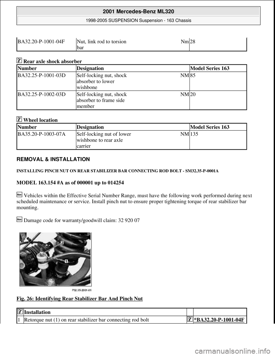
Fig. 26: Identifying Rear Stabilizer Bar And Pinch Nut
BA32.20-P-1001-04FNut, link rod to torsion
barNm28
NumberDesignationModel Series 163
BA32.25-P-1001-03DSelf-locking nut, shock
absorber to lower
wishboneNM85
BA32.25-P-1002-03DSelf-locking nut, shock
absorber to frame side
memberNM20
NumberDesignationModel Series 163
BA35.20-P-1003-07ASelf-locking nut of lower
wishbone to rear axle
carrierNM135
Installation
1Retorque nut (1) on rear stabilizer bar connecting rod bolt*BA32.20-P-1001-04F
2001 Mercedes-Benz ML320
1998-2005 SUSPENSION Suspension - 163 Chassis
me
Saturday, October 02, 2010 3:37:36 PMPage 27 © 2006 Mitchell Repair Information Company, LLC.
Page 3990 of 4133

8
Install spacer ring (2) and screw on union nut
(1) as far as the stop.
Counterhold valve body (3) using
installation tool for tire pressure monitor or pin
4
2 mm (4) in drill hole (arrow).
Installation tool for tire pressure monitor
*WH58.30-Z-1040-06A
9
Tighten union nut (1).
Secure valve body (2) using installation
tool for tire pressure monitor or pin
4
2 mm
(4), to prevent it from turning
After tightening, pull installation tool for
tire pressure monitor or pin
4
2 mm (4) out of
valve body (3). Danger of damage to tire.
Union nut to valve body
*BA40.15-P-1001-01A
Installation tool for tire pressure monitor
*WH58.30-Z-1040-06A
10
Press RPM wheel sensor gently into drop
center of rim and tighten bolt (5).
Internal torx bolt, wheel sensor to valve
body
*BA40.15-P-1002-01A
11
Note ID code (b) of new TPM wheel sensor.
It is advisable to record the code in the
owner's manual or maintenance booklet.
Initialization
12
Teach in new TPM wheel sensor in TPM
control unit using STAR DIAGNOSIS.
Diagnosis system STAR DIAGNOSIS
*WE58.40-Z-1013-06A
13
Activate the tire pressure monitoring system
Model 211
AR54.30-P-1000-02RAT
Model 230
AR54.30-P-1000-02RAR
Model 240
AR54.30-P-1000-02RAH
n
Tire pressure monitor (TPM), activation
Model 210
GF40.15-P-0001-02A
Model 215, 220 up to 30.9.00
GF40.15-P-0001-02B
Model 215, 220 as of 01.10.00 up to 31.05.01
GF40.15-P-0001-02C
Models 215, 220 as of 01.06.01 up to 31.08.02
GF40.15-P-0001-02D
Model 215, 220 as of 01.09.02
GF40.15-P-0001-02E
Tire pressure monitoring
Number
Designation
Model
210, 211,
215, 220,
230, 240
BA40.15-P-1001-01A
Union nut to valve body
Nm
4
BA40.15-P-1002-01A
Bolt, wheel sensor to valve body
Nm
4
Commercially available tools
(see Workshop Equipment Manual)
Number
Designation
Make (e. g.)
Order number
WH58.30-Z-1040-06A
Installation tool for tire pressure control
Alligator Ventilfabrik
GmbH
Postfach 1120
D-89526 Giengen
232540
Workshop equipment/MB testers
(see Workshop Equipment Manual)
WE58.40-Z-1013-06A
STAR DIAGNOSIS Compact diagnosis system for passenger cars, order number 6511 1801 00
Copyright DaimlerChrysler AG 06.07.2006 CD-Ausgabe G/10/04 . This WIS print-out will not be recorde
d by Modification services.
Page 2