wiring MERCEDES-BENZ ML320 1997 Complete Manual PDF
[x] Cancel search | Manufacturer: MERCEDES-BENZ, Model Year: 1997, Model line: ML320, Model: MERCEDES-BENZ ML320 1997Pages: 4133, PDF Size: 88.89 MB
Page 1759 of 4133
INSTALLING AUXILIARY CABLE HARNESS ON SIDE WALL TAILLAMP - AR82.10-P-4920-01GH
Models 163.154/174 as of VINA289565 to VIN A371934, model 163.175 up to VIN A371934 with USA
version code 494a
1. Insert plug (1) of auxiliary cable harness (2) in socket (3) of side-marker lamp.
2. Insert the plug on the other end of the wiring harness in the free connection pins in the opening (4) of the
lamp support (5).
The brown line (ground) should be on the outside. Ensure that the plugs are completely pushed onto
the connection pins.
3. Seal the lines and opening (4) with a thermoplastic adhesive gun.
Give the adhesive sufficient time to dr
y before installing the taillamp.
distance of the cover to
the bumper is even.
5Unhook left front
headlamp unit (E1) or
right front headlamp unit
(E2) from the hole (arrow
B) using drift (4) and pull
forwards
6Disconnect headlamp
harness connector (X24)
7Remove headlamp unit
toward front
8Install in the reverse order
9Perform function check
10Check and correct
headlamp adjustment
Check and correct
headlamp adjustment AP82.10-P-8260GH
2001 Mercedes-Benz ML320
1998-2005 ACCESSORIES & BODY, CAB Electrical System - Body - 163 Chassis
me
Saturday, October 02, 2010 3:30:09 PMPage 264 © 2006 Mitchell Repair Information Company, LLC.
Page 1761 of 4133
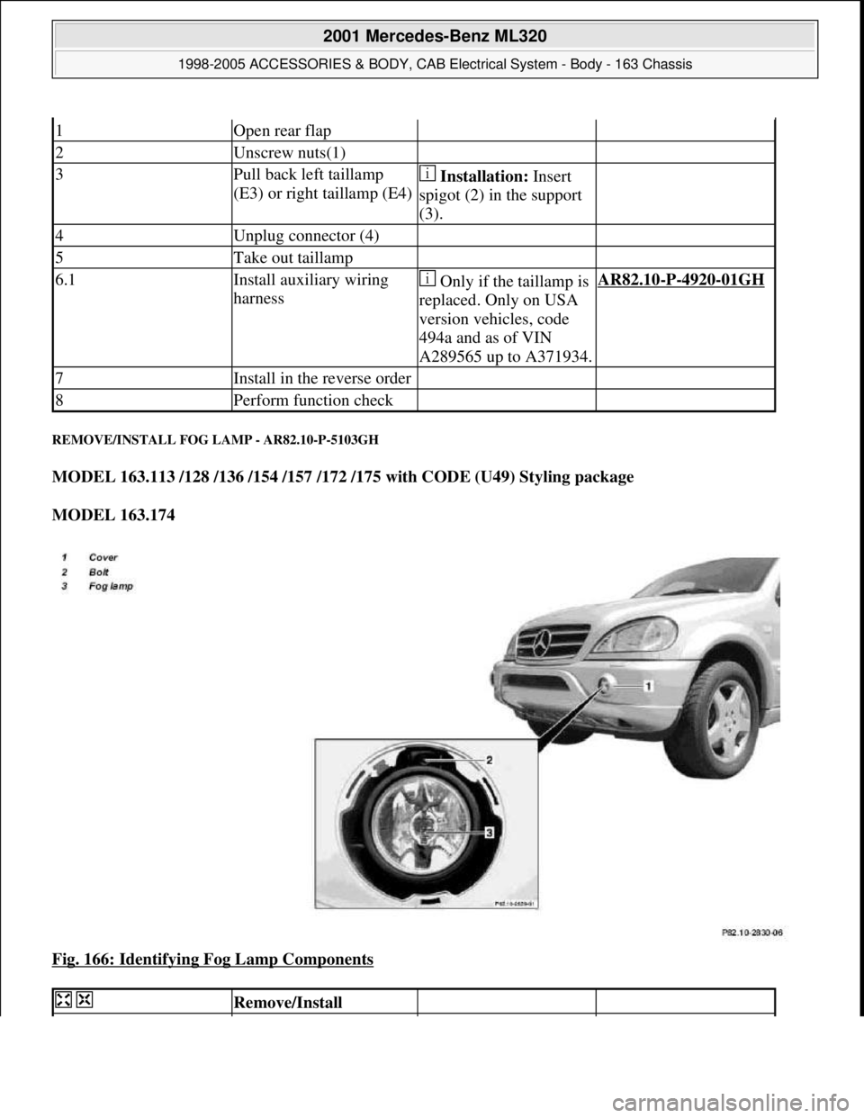
REMOVE/INSTALL FOG LAMP - AR82.10-P-5103GH
MODEL 163.113 /128 /136 /154 /157 /172 /175 with CODE (U49) Styling package
MODEL 163.174
Fig. 166: Identifying Fog Lamp Components
1Open rear flap
2Unscrew nuts(1)
3Pull back left taillamp
(E3) or right taillamp (E4) Installation: Insert
spigot (2) in the support
(3).
4Unplug connector (4)
5Take out taillamp
6.1Install auxiliary wiring
harness Only if the taillamp is
replaced. Only on USA
version vehicles, code
494a and as of VIN
A289565 up to A371934.AR82.10-P-4920-01GH
7Install in the reverse order
8Perform function check
Remove/Install
2001 Mercedes-Benz ML320
1998-2005 ACCESSORIES & BODY, CAB Electrical System - Body - 163 Chassis
me
Saturday, October 02, 2010 3:30:09 PMPage 266 © 2006 Mitchell Repair Information Company, LLC.
Page 1780 of 4133
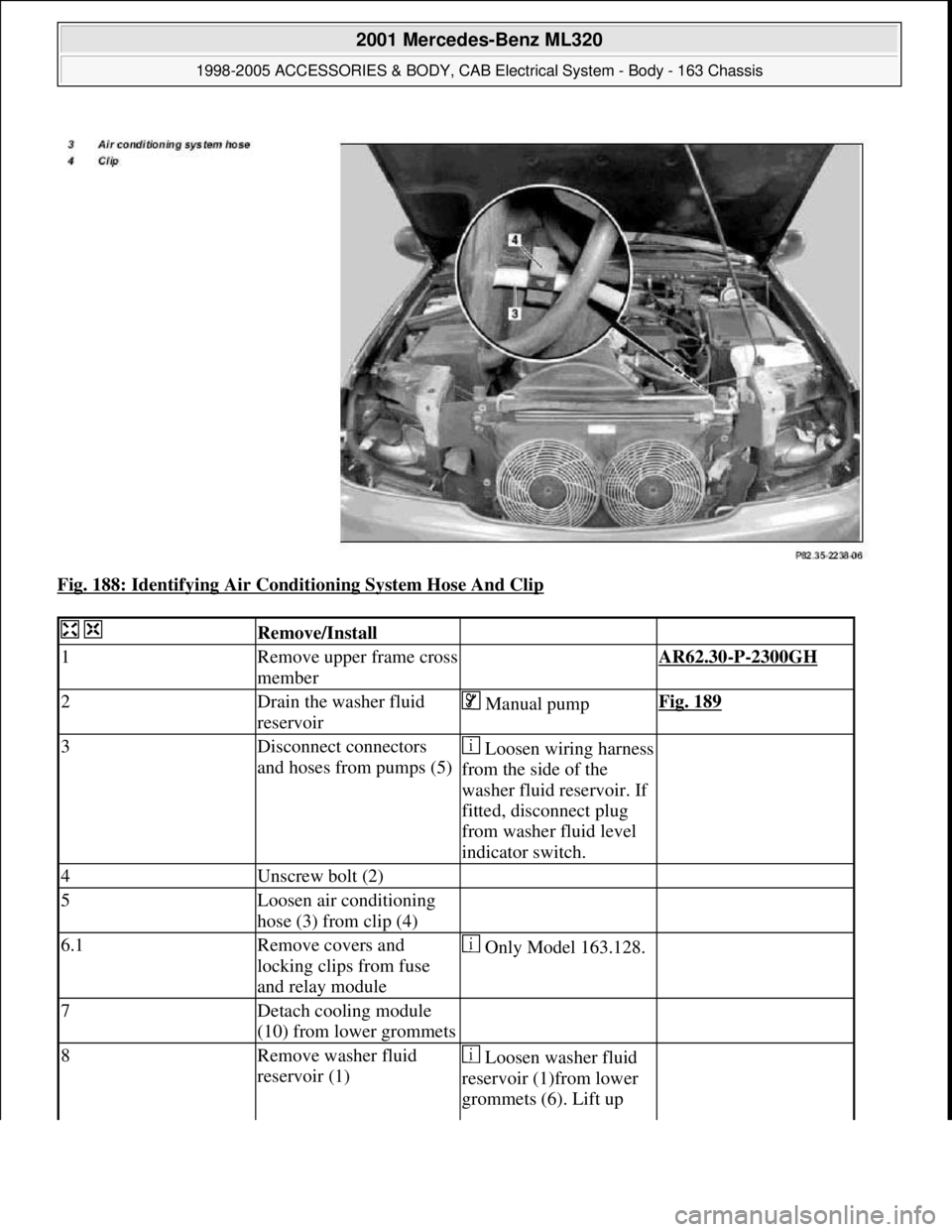
Fig. 188: Identifying Air Conditioning System Hose And Clip
Remove/Install
1Remove upper frame cross
member AR62.30-P-2300GH
2Drain the washer fluid
reservoir Manual pumpFig. 189
3Disconnect connectors
and hoses from pumps (5)Loosen wiring harness
from the side of the
washer fluid reservoir. If
fitted, disconnect plug
from washer fluid level
indicator switch.
4Unscrew bolt (2)
5Loosen air conditioning
hose (3) from clip (4)
6.1Remove covers and
locking clips from fuse
and relay module Only Model 163.128.
7Detach cooling module
(10) from lower grommets
8Remove washer fluid
reservoir (1) Loosen washer fluid
reservoir (1)from lower
grommets (6). Lift up
2001 Mercedes-Benz ML320
1998-2005 ACCESSORIES & BODY, CAB Electrical System - Body - 163 Chassis
me
Saturday, October 02, 2010 3:30:09 PMPage 285 © 2006 Mitchell Repair Information Company, LLC.
Page 1788 of 4133
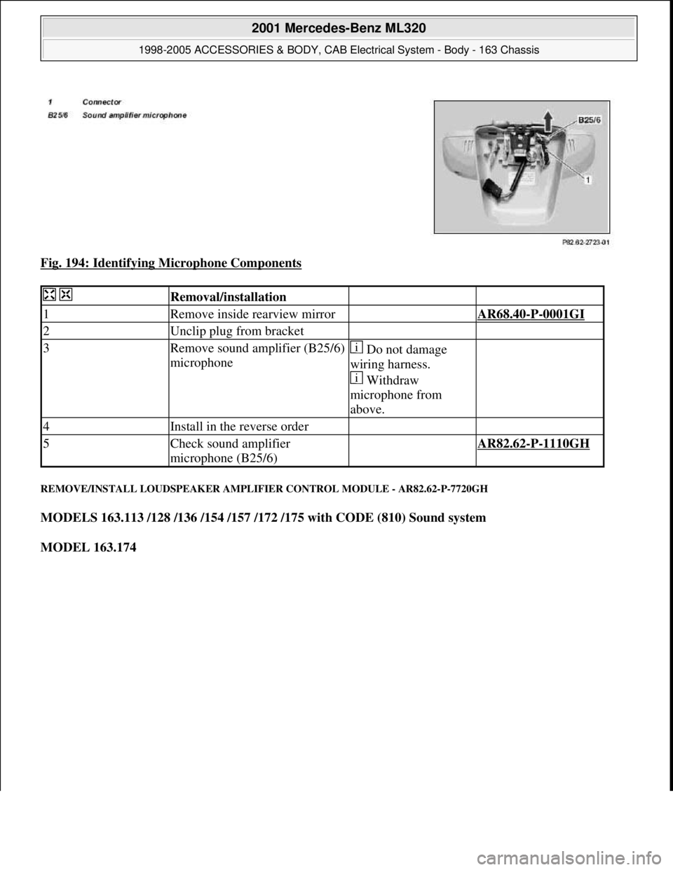
Fig. 194: Identifying Microphone Components
REMOVE/INSTALL LOUDSPEAKER AMPLIFIER CONTROL MODULE - AR82.62-P-7720GH
MODELS 163.113 /128 /136 /154 /157 /172 /175 with CODE (810) Sound system
MODEL 163.174
Removal/installation
1Remove inside rearview mirror AR68.40-P-0001GI
2Unclip plug from bracket
3Remove sound amplifier (B25/6)
microphone Do not damage
wiring harness.
Withdraw
microphone from
above.
4Install in the reverse order
5Check sound amplifier
microphone (B25/6) AR82.62-P-1110GH
2001 Mercedes-Benz ML320
1998-2005 ACCESSORIES & BODY, CAB Electrical System - Body - 163 Chassis
me
Saturday, October 02, 2010 3:30:09 PMPage 293 © 2006 Mitchell Repair Information Company, LLC.
Page 1796 of 4133
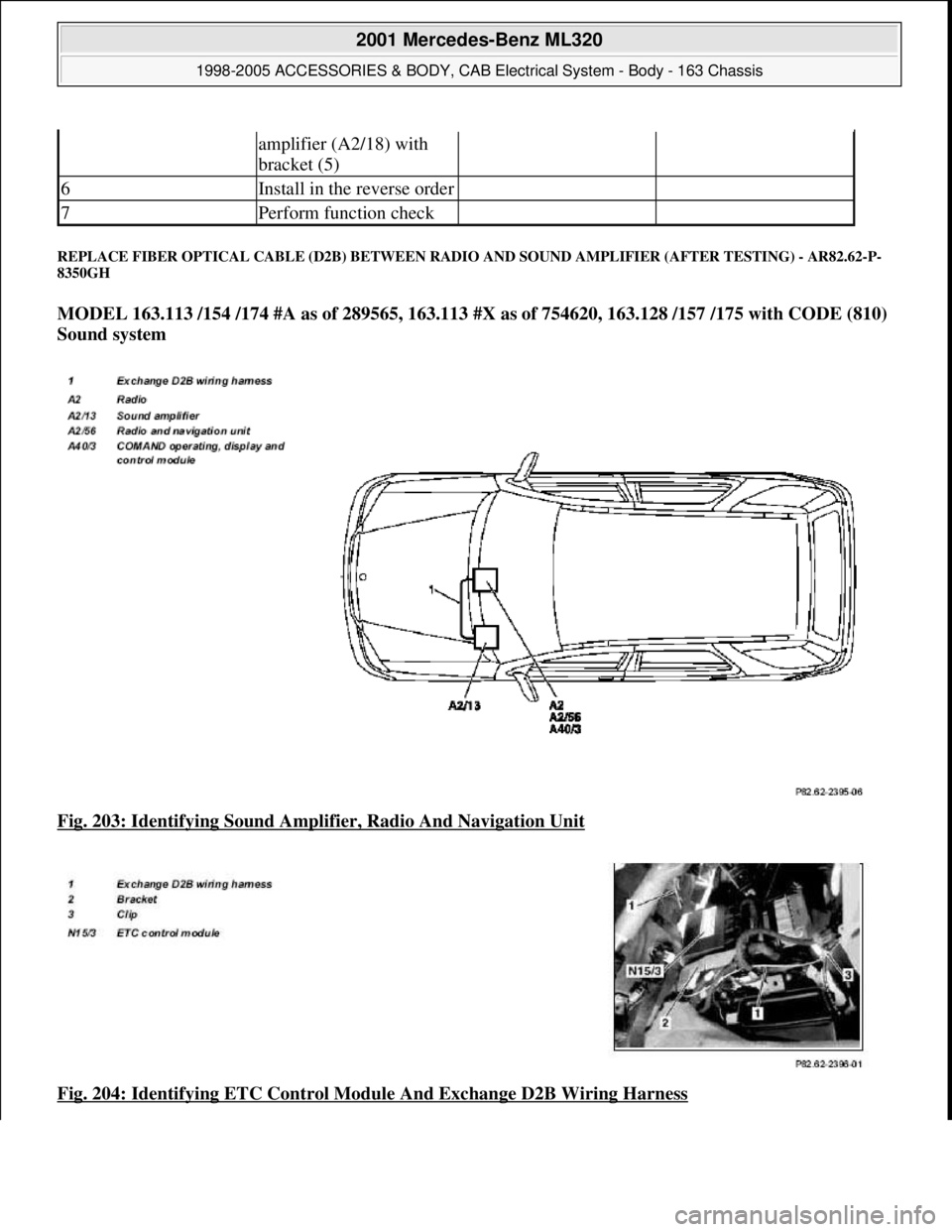
REPLACE FIBER OPTICAL CA BLE (D2B) BETWEEN RADIO AND SOUND AMPLIFIER (AFTER TESTING) - AR82.62-P-
8350GH
MODEL 163.113 /154 /174 #A as of 289565, 163.113 #X as of 754620, 163.128 /157 /175 with CODE (810)
Sound system
Fig. 203: Identifying Sound Amplif ier, Radio And Navigation Unit
Fig. 204: Identifying ETC Control Modul e And Exchange D2B Wiring Harness
amplifier (A2/18) with
bracket (5)
6Install in the reverse order
7Perform function check
2001 Mercedes-Benz ML320
1998-2005 ACCESSORIES & BODY, CAB Electr ical System - Body - 163 Chassis
me
Saturday, October 02, 2010 3:30:10 PMPage 301 © 2006 Mitchell Repair Information Company, LLC.
Page 1797 of 4133
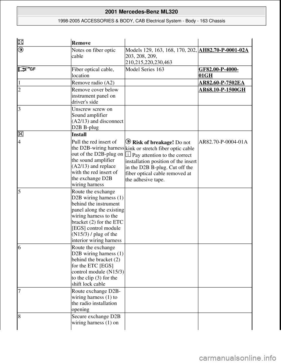
Remove
Notes on fiber optic
cableModels 129, 163, 168, 170, 202,
203, 208, 209,
210,215,220,230,463AH82.70-P-0001-02A
Fiber optical cable,
locationModel Series 163GF82.00-P-4000-
01GH
1Remove radio (A2) AR82.60-P-7502EA
2Remove cover below
instrument panel on
driver's side AR68.10-P-1500GH
3Unscrew screw on
Sound amplifier
(A2/13) and disconnect
D2B B-plug
Install
4Pull the red insert of
the D2B-wiring harness
out of the D2B-plug on
the sound amplifier
(A2/13) and replace
with the red insert of
the exchange D2B
wiring harness Risk of breakage! Do not
kink or stretch fiber optic cable
Pay attention to the correct
installation position of the insert
in the D2B B-plug. Cut off the
fiber optical cable removed at
the adhesive tape.AR82.70-P-0004-01A
5Route the exchange
D2B wiring harness (1)
behind the instrument
panel along the existing
wiring harness to the
bracket (2) for the ETC
[EGS] control module
(N15/3) / plug of the
interior wiring harness
6Route the exchange
D2B wiring harness (1)
behind the bracket (2)
for the ETC [EGS]
control module (N15/3)
to the clip (3) for the
shift lock cable
7Route exchange D2B-
wiring harness (1) to
the radio installation
opening
8Secure exchange D2B
wiring harness (1) on
2001 Mercedes-Benz ML320
1998-2005 ACCESSORIES & BODY, CAB Electrical System - Body - 163 Chassis
me
Saturday, October 02, 2010 3:30:10 PMPage 302 © 2006 Mitchell Repair Information Company, LLC.
Page 1798 of 4133
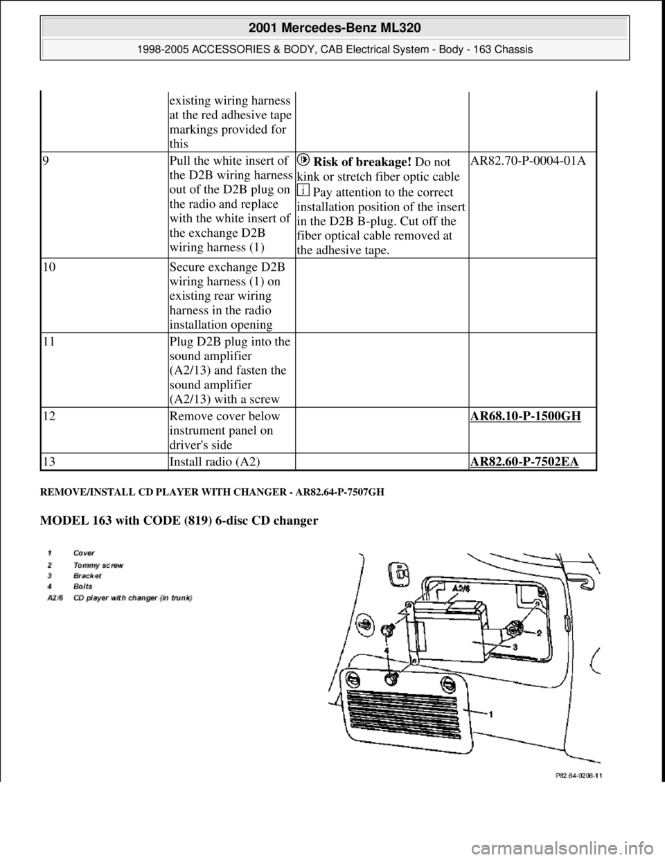
REMOVE/INSTALL CD PLAYER WITH CHANGER - AR82.64-P-7507GH
MODEL 163 with CODE (819) 6-disc CD changer
existing wiring harness
at the red adhesive tape
markings provided for
this
9Pull the white insert of
the D2B wiring harness
out of the D2B plug on
the radio and replace
with the white insert of
the exchange D2B
wiring harness (1) Risk of breakage! Do not
kink or stretch fiber optic cable
Pay attention to the correct
installation position of the insert
in the D2B B-plug. Cut off the
fiber optical cable removed at
the adhesive tape.AR82.70-P-0004-01A
10Secure exchange D2B
wiring harness (1) on
existing rear wiring
harness in the radio
installation opening
11Plug D2B plug into the
sound amplifier
(A2/13) and fasten the
sound amplifier
(A2/13) with a screw
12Remove cover below
instrument panel on
driver's side AR68.10-P-1500GH
13Install radio (A2) AR82.60-P-7502EA
2001 Mercedes-Benz ML320
1998-2005 ACCESSORIES & BODY, CAB Electrical System - Body - 163 Chassis
me
Saturday, October 02, 2010 3:30:10 PMPage 303 © 2006 Mitchell Repair Information Company, LLC.
Page 1801 of 4133
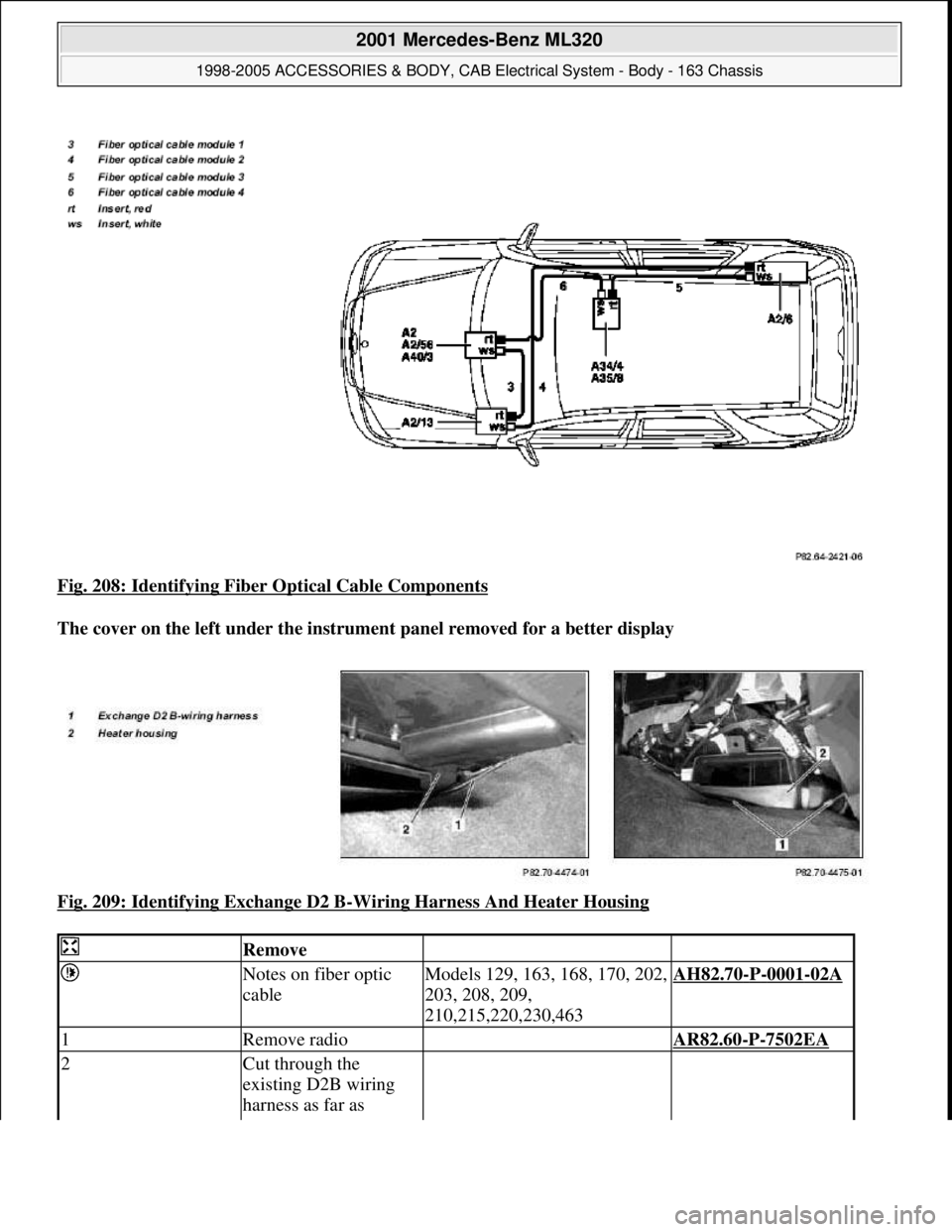
Fig. 208: Identifying Fiber Optical Cable Components
The cover on the left under the instrume nt panel removed for a better display
Fig. 209: Identifying Exchange D2 B
-Wiring Harness And Heater Housing
Remove
Notes on fiber optic
cableModels 129, 163, 168, 170, 202,
203, 208, 209,
210,215,220,230,463AH82.70-P-0001-02A
1Remove radio AR82.60-P-7502EA
2Cut through the
existing D2B wiring
harness as far as
2001 Mercedes-Benz ML320
1998-2005 ACCESSORIES & BODY, CAB Electr ical System - Body - 163 Chassis
me
Saturday, October 02, 2010 3:30:10 PMPage 306 © 2006 Mitchell Repair Information Company, LLC.
Page 1802 of 4133
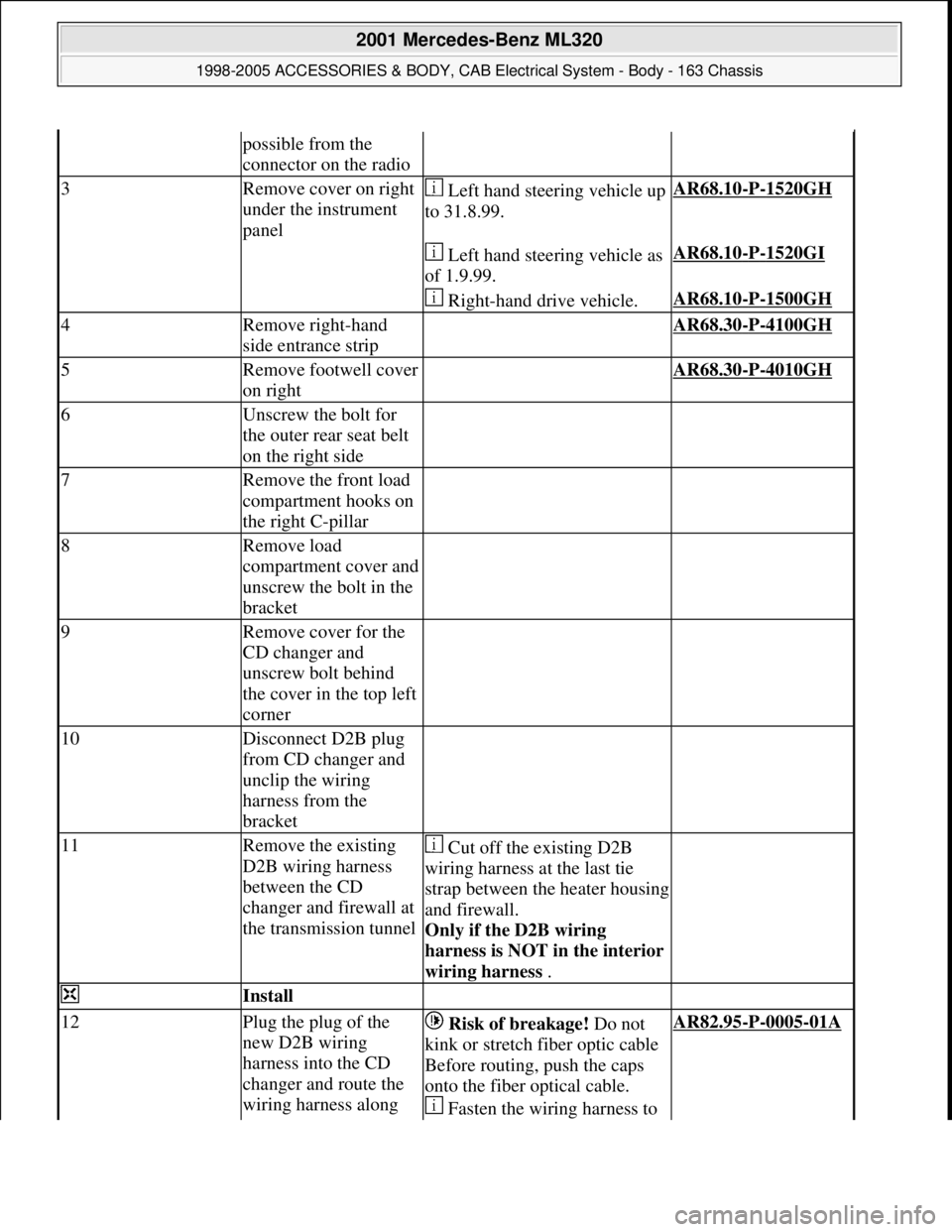
possible from the
connector on the radio
3Remove cover on right
under the instrument
panel Left hand steering vehicle up
to 31.8.99.AR68.10-P-1520GH
Left hand steering vehicle as
of 1.9.99.AR68.10-P-1520GI
Right-hand drive vehicle.AR68.10-P-1500GH
4Remove right-hand
side entrance strip AR68.30-P-4100GH
5Remove footwell cover
on right AR68.30-P-4010GH
6Unscrew the bolt for
the outer rear seat belt
on the right side
7Remove the front load
compartment hooks on
the right C-pillar
8Remove load
compartment cover and
unscrew the bolt in the
bracket
9Remove cover for the
CD changer and
unscrew bolt behind
the cover in the top left
corner
10Disconnect D2B plug
from CD changer and
unclip the wiring
harness from the
bracket
11Remove the existing
D2B wiring harness
between the CD
changer and firewall at
the transmission tunnel Cut off the existing D2B
wiring harness at the last tie
strap between the heater housing
and firewall.
Only if the D2B wiring
harness is NOT in the interior
wiring harness .
Install
12Plug the plug of the
new D2B wiring
harness into the CD
changer and route the
wiring harness along Risk of breakage! Do not
kink or stretch fiber optic cable
Before routing, push the caps
onto the fiber optical cable.
Fasten the wiring harness to AR82.95-P-0005-01A
2001 Mercedes-Benz ML320
1998-2005 ACCESSORIES & BODY, CAB Electrical System - Body - 163 Chassis
me
Saturday, October 02, 2010 3:30:10 PMPage 307 © 2006 Mitchell Repair Information Company, LLC.
Page 1803 of 4133
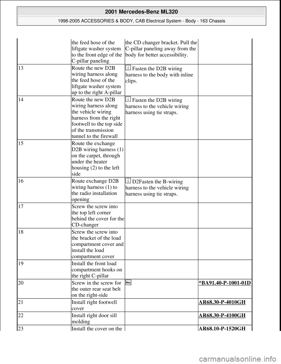
the feed hose of the
liftgate washer system
to the front edge of the
C-pillar panelingthe CD changer bracket. Pull the
C-pillar paneling away from the
body for better accessibility.
13Route the new D2B
wiring harness along
the feed hose of the
liftgate washer system
up to the right A-pillar Fasten the D2B wiring
harness to the body with inline
clips.
14Route the new D2B
wiring harness along
the vehicle wiring
harness from the right
footwell to the top side
of the transmission
tunnel to the firewall Fasten the D2B wiring
harness to the vehicle wiring
harness using tie straps.
15Route the exchange
D2B wiring harness (1)
on the carpet, through
under the heater
housing (2) to the left
side
16Route exchange D2B
wiring harness (1) to
the radio installation
opening D2Fasten the B-wiring
harness to the vehicle wiring
harness using tie straps.
17Screw the screw into
the top left corner
behind the cover for the
CD-changer
18Screw the screw into
the bracket of the load
compartment cover and
install the load
compartment cover
19Install the front load
compartment hooks on
the right C-pillar
20Screw in the screw for
the outer rear seat belt
on the right-side *BA91.40-P-1001-01D
21Install right footwell
cover AR68.30-P-4010GH
22Install right door sill
molding AR68.30-P-4100GH
23Install the cover on the AR68.10-P-1520GH
2001 Mercedes-Benz ML320
1998-2005 ACCESSORIES & BODY, CAB Electrical System - Body - 163 Chassis
me
Saturday, October 02, 2010 3:30:10 PMPage 308 © 2006 Mitchell Repair Information Company, LLC.