612.963 in MODEL 163.113 MERCEDES-BENZ ML320 1997 Complete Repair Manual
[x] Cancel search | Manufacturer: MERCEDES-BENZ, Model Year: 1997, Model line: ML320, Model: MERCEDES-BENZ ML320 1997Pages: 4133, PDF Size: 88.89 MB
Page 1210 of 4133
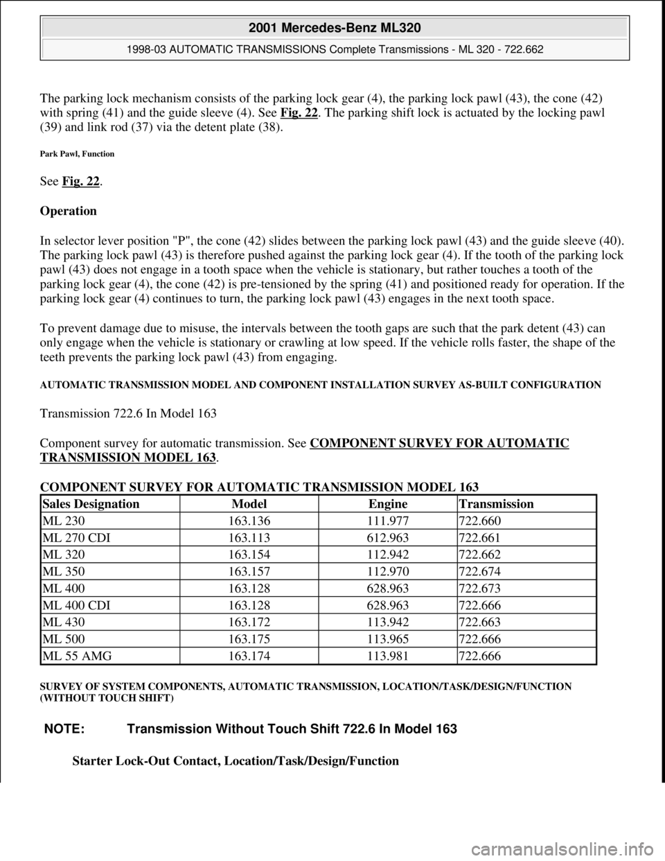
The parking lock mechanism consists of the parking lock gear (4), the parking lock pawl (43), the cone (42)
with spring (41) and the guide sleeve (4). See Fig. 22
. The parking shift lock is actuated by the locking pawl
(39) and link rod (37) via the detent plate (38).
Park Pawl, Function
See Fig. 22.
Operation
In selector lever position "P", the cone (42) slides between the parking lock pawl (43) and the guide sleeve (40).
The parking lock pawl (43) is therefore pushed against the parking lock gear (4). If the tooth of the parking lock
pawl (43) does not engage in a tooth space when the vehicle is stationary, but rather touches a tooth of the
parking lock gear (4), the cone (42) is pre-tensioned by the spring (41) and positioned ready for operation. If the
parking lock gear (4) continues to turn, the parking lock pawl (43) engages in the next tooth space.
To prevent damage due to misuse, the intervals between the tooth gaps are such that the park detent (43) can
only engage when the vehicle is stationary or crawling at low speed. If the vehicle rolls faster, the shape of the
teeth prevents the parking lock pawl (43) from engaging.
AUTOMATIC TRANSMISSION MODEL AND COMPONENT INSTALLATION SURVEY AS-BUILT CONFIGURATION
Transmission 722.6 In Model 163
Component survey for automatic transmission. See COMPONENT SURVEY FOR AUTOMATIC
TRANSMISSION MODEL 163.
COMPONENT SURVEY FOR AUTOMATIC TRANSMISSION MODEL 163
SURVEY OF SYSTEM COMPONENTS, AUTOMATIC TRANSMISSION, LOCATION/TASK/DESIGN/FUNCTION
(WITHOUT TOUCH SHIFT)
Starter Lock-Out Contact, Location/Task/Design/Function
Sales DesignationModelEngineTransmission
ML 230163.136111.977722.660
ML 270 CDI163.113612.963722.661
ML 320163.154112.942722.662
ML 350163.157112.970722.674
ML 400163.128628.963722.673
ML 400 CDI163.128628.963722.666
ML 430163.172113.942722.663
ML 500163.175113.965722.666
ML 55 AMG163.174113.981722.666
NOTE: Transmission Without Touch Shift 722.6 In Model 163
2001 Mercedes-Benz ML320
1998-03 AUTOMATIC TRANSMISSIONS Complete Transmissions - ML 320 - 722.662
me
Saturday, October 02, 2010 3:15:26 PMPage 41 © 2006 Mitchell Repair Information Company, LLC.
Page 1468 of 4133
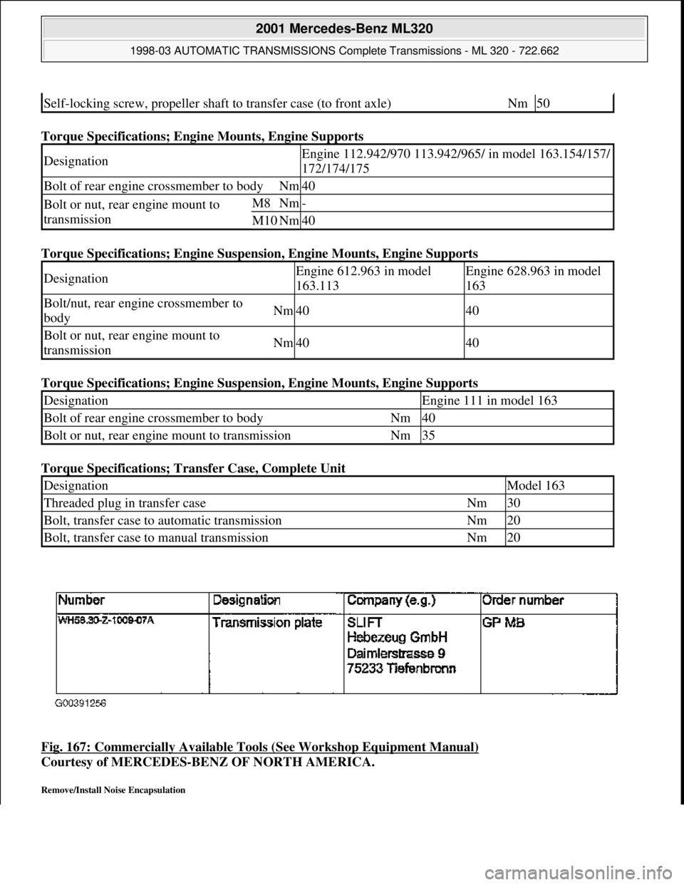
Torque Specifications; Engine Mounts, Engine Supports
Torque Specifications; Engine Suspension, Engine Mounts, Engine Supports
Torque Specifications; Engine Suspension, Engine Mounts, Engine Supports
Torque Specifications; Transfer Case, Complete Unit
Fig. 167: Commercially Available Tools (See Workshop Equipment Manual)
Courtesy of MERCEDES-BENZ OF NORTH AMERICA.
Remove/Install Noise Encapsulation
Self-locking screw, propeller shaft to transfer case (to front axle)Nm50
DesignationEngine 112.942/970 113.942/965/ in model 163.154/157/
172/174/175
Bolt of rear engine crossmember to bodyNm40
Bolt or nut, rear engine mount to
transmissionM8Nm-
M10Nm40
DesignationEngine 612.963 in model
163.113Engine 628.963 in model
163
Bolt/nut, rear engine crossmember to
bodyNm4040
Bolt or nut, rear engine mount to
transmissionNm4040
DesignationEngine 111 in model 163
Bolt of rear engine crossmember to bodyNm40
Bolt or nut, rear engine mount to transmissionNm35
DesignationModel 163
Threaded plug in transfer caseNm30
Bolt, transfer case to automatic transmissionNm20
Bolt, transfer case to manual transmissionNm20
2001 Mercedes-Benz ML320
1998-03 AUTOMATIC TRANSMISSIONS Complete Transmissions - ML 320 - 722.662
me
Saturday, October 02, 2010 3:15:30 PMPage 299 © 2006 Mitchell Repair Information Company, LLC.
Page 2030 of 4133
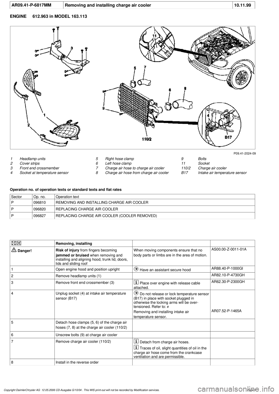
AR09.41-P-6817MM
Removing and installing charge air cooler
10.11.99
ENGINE
612.963 in MODEL 163.113
P09.41-2024-09
1
Headlamp units
2
Cover strips
3
Front end crossmember
4
Socket at temperature sensor
9
Bolts
11
Socket
110/2
Charge air cooler
B17
Intake air temperature sensor
5
Right hose clamp
6
Left hose clamp
7
Charge air hose to charge air cooler
8
Charge air hose from charge air cooler
Operation no. of operation texts or standard texts and flat rates
Sector
Op. no.
Operation text
P
096810
REMOVING AND INSTALLING CHARGE AIR COOLER
P
096820
REPLACING CHARGE AIR COOLER
P
096827
REPLACING CHARGE AIR COOLER (COOLER REMOVED)
Removing, installing
Danger!
Risk of injury
from fingers becoming
jammed or bruised
when removing and
installing and aligning hood, trunk lid, doors,
lids and sliding roof
When moving components ensure that no
body parts or limbs are in the area of motion.
AS00.00-Z-0011-01A
1
Open engine hood and position upright
Have an assistant secure hood
AR88.40-P-1000GI
2
Remove headlamp units (1)
AR82.10-P-4730GH
3
Remove front end crossmember (3)
Place over engine with release cable
attached.
AR62.30-P-2300GH
4
Unplug socket (4) at intake air temperature
sensor (B17)
Do not release or lock temperature sensor
(B17) in place with socket plugged in
otherwise the locking arms will be over-
tensioned. Refer to:
#
Removing and installing intake air
temperature sensor.
AR07.52-P-1465A
5
Detach hose clamps (5, 6) of the charge air
hoses (7, 8) at the charge air cooler (110/2)
6
Unscrew bolts (9) at charge air cooler
7
Remove charge air cooler (110/2)
Detach from charge air hoses.
Traces of oil, slight quantities of oil in the
charge air hose come from the crankcase
ventilation and are permissible.
8
Install in the reverse order
Copyright DaimlerChrysler AG 12.05.2006 CD-Ausgabe G/10/04 . This WIS print-out will not be recorde
d by Modification services.
Page 1
Page 2032 of 4133
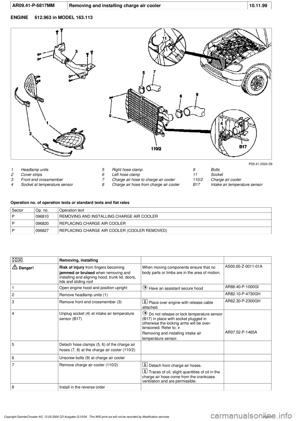
AR09.41-P-6817MM
Removing and installing charge air cooler
10.11.99
ENGINE
612.963 in MODEL 163.113
P09.41-2024-09
1
Headlamp units
2
Cover strips
3
Front end crossmember
4
Socket at temperature sensor
9
Bolts
11
Socket
110/2
Charge air cooler
B17
Intake air temperature sensor
5
Right hose clamp
6
Left hose clamp
7
Charge air hose to charge air cooler
8
Charge air hose from charge air cooler
Operation no. of operation texts or standard texts and flat rates
Sector
Op. no.
Operation text
P
096810
REMOVING AND INSTALLING CHARGE AIR COOLER
P
096820
REPLACING CHARGE AIR COOLER
P
096827
REPLACING CHARGE AIR COOLER (COOLER REMOVED)
Removing, installing
Danger!
Risk of injury
from fingers becoming
jammed or bruised
when removing and
installing and aligning hood, trunk lid, doors,
lids and sliding roof
When moving components ensure that no
body parts or limbs are in the area of motion.
AS00.00-Z-0011-01A
1
Open engine hood and position upright
Have an assistant secure hood
AR88.40-P-1000GI
2
Remove headlamp units (1)
AR82.10-P-4730GH
3
Remove front end crossmember (3)
Place over engine with release cable
attached.
AR62.30-P-2300GH
4
Unplug socket (4) at intake air temperature
sensor (B17)
Do not release or lock temperature sensor
(B17) in place with socket plugged in
otherwise the locking arms will be over-
tensioned. Refer to:
#
Removing and installing intake air
temperature sensor.
AR07.52-P-1465A
5
Detach hose clamps (5, 6) of the charge air
hoses (7, 8) at the charge air cooler (110/2)
6
Unscrew bolts (9) at charge air cooler
7
Remove charge air cooler (110/2)
Detach from charge air hoses.
Traces of oil, slight quantities of oil in the
charge air hose come from the crankcase
ventilation and are permissible.
8
Install in the reverse order
Copyright DaimlerChrysler AG 12.05.2006 CD-Ausgabe G/10/04 . This WIS print-out will not be recorde
d by Modification services.
Page 1
Page 2068 of 4133
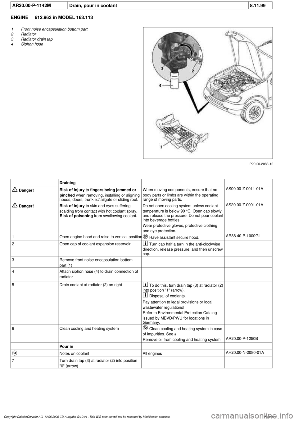
AR20.00-P-1142M
Drain, pour in coolant
8.11.99
ENGINE
612.963 in MODEL 163.113
P20.20-2083-12
1
Front noise encapsulation bottom part
2
Radiator
3
Radiator drain tap
4
Siphon hose
Draining
Danger!
Risk of injury
to
fingers being jammed or
pinched
when removing, installing or aligning
hoods, doors, trunk lid/tailgate or sliding roof.
When moving components, ensure that no
body parts or limbs are within the operating
range of moving parts.
AS00.00-Z-0011-01A
Danger!
Risk of injury
to skin and eyes suffering
scalding from contact with hot coolant spray.
Risk of poisoning
from swallowing coolant.
Do not open cooling system unless coolant
temperature is below 90 °C. Open cap slowly
and release the pressure. Do not pour coolant
into beverage bottles.
Wear protective gloves, protective clothing
and eye protection.
AS20.00-Z-0001-01A
1
Open engine hood and raise to vertical position
Have assistant secure hood.
AR88.40-P-1000GI
2
Open cap of coolant expansion reservoir
Turn cap half a turn in the anti-clockwise
direction, release pressure, and then unscrew
cap.
3
Remove front noise encapsulation bottom
part (1)
4
Attach siphon hose (4) to drain connection of
radiator
5
Drain coolant at radiator (2) on right
To do this, turn drain tap (3) at radiator (2)
into position "1" (arrow).
Disposal of coolants.
Pay attention to legal provisions or local
wastewater regulations!
Refer to Environmental Protection Catalog
issued by MBVD/PWU for locations in
Germany.
6
Clean cooling and heating system
Clean cooling and heating system in case
of impurities. See
#
Remove oil from cooling and heating system.
AR20.00-P-1250B
Pour in
Notes on coolant
All engines
AH20.00-N-2080-01A
7
Turn drain tap (3) at radiator (2) into position
"0" (arrow)
Copyright DaimlerChrysler AG 12.05.2006 CD-Ausgabe G/10/04 . This WIS print-out will not be recorde
d by Modification services.
Page 1
Page 2069 of 4133

Danger!
Risk of accident
caused by vehicle starting
off by itself when engine is running.
Risk of
injury
caused by contusions and burns when
working in engine during starting procedure
Secure vehicle to prevent it from moving.
Wear closed and snug-fitting work clothes.
Do not grasp hot or rotating parts.
AS00.00-Z-0005-01A
8
Pour in coolant
Warm up engine by running at moderate
revs. Top up coolant constantly at coolant
expansion reservoir. Close coolant expansion
tank once
coolant temperature is 60-70 °C.
*BF20.00-P-1001-02E
Note on coolant level
Model 124, 129, 140, 163.113, 168, 170, 202,
208, 210, 220, 463
AH20.00-P-1142-01A
9
Inspect cooling system for leaks
AR20.00-P-1010HA
Cooling system
Number
Designation
Engine
612.963
BF20.00-P-1001-02E
Cooling system
Total capacity
Liter
Y
11.0
Filling capacity of anticorrosion/
antifreeze agent down to
-37 °C
Liter
Y
5.5
Filling capacity of anticorrosion/
antifreeze up to -45 °C
Liter
Y
6.25
Specifications for Operating
Fluids
SheetBB00.40-P-0310-01A
SheetBB00.40-P-0325-00A
Copyright DaimlerChrysler AG 12.05.2006 CD-Ausgabe G/10/04 . This WIS print-out will not be recorde
d by Modification services.
Page 2
Page 2075 of 4133
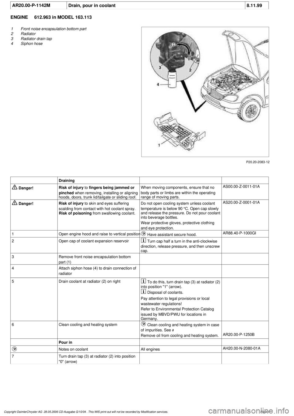
AR20.00-P-1142M
Drain, pour in coolant
8.11.99
ENGINE
612.963 in MODEL 163.113
P20.20-2083-12
1
Front noise encapsulation bottom part
2
Radiator
3
Radiator drain tap
4
Siphon hose
Draining
Danger!
Risk of injury
to
fingers being jammed or
pinched
when removing, installing or aligning
hoods, doors, trunk lid/tailgate or sliding roof.
When moving components, ensure that no
body parts or limbs are within the operating
range of moving parts.
AS00.00-Z-0011-01A
Danger!
Risk of injury
to skin and eyes suffering
scalding from contact with hot coolant spray.
Risk of poisoning
from swallowing coolant.
Do not open cooling system unless coolant
temperature is below 90 °C. Open cap slowly
and release the pressure. Do not pour coolant
into beverage bottles.
Wear protective gloves, protective clothing
and eye protection.
AS20.00-Z-0001-01A
1
Open engine hood and raise to vertical position
Have assistant secure hood.
AR88.40-P-1000GI
2
Open cap of coolant expansion reservoir
Turn cap half a turn in the anti-clockwise
direction, release pressure, and then unscrew
cap.
3
Remove front noise encapsulation bottom
part (1)
4
Attach siphon hose (4) to drain connection of
radiator
5
Drain coolant at radiator (2) on right
To do this, turn drain tap (3) at radiator (2)
into position "1" (arrow).
Disposal of coolants.
Pay attention to legal provisions or local
wastewater regulations!
Refer to Environmental Protection Catalog
issued by MBVD/PWU for locations in
Germany.
6
Clean cooling and heating system
Clean cooling and heating system in case
of impurities. See
#
Remove oil from cooling and heating system.
AR20.00-P-1250B
Pour in
Notes on coolant
All engines
AH20.00-N-2080-01A
7
Turn drain tap (3) at radiator (2) into position
"0" (arrow)
Copyright DaimlerChrysler AG 28.05.2006 CD-Ausgabe G/10/04 . This WIS print-out will not be recorde
d by Modification services.
Page 1
Page 2076 of 4133

Danger!
Risk of accident
caused by vehicle starting
off by itself when engine is running.
Risk of
injury
caused by contusions and burns when
working in engine during starting procedure
Secure vehicle to prevent it from moving.
Wear closed and snug-fitting work clothes.
Do not grasp hot or rotating parts.
AS00.00-Z-0005-01A
8
Pour in coolant
Warm up engine by running at moderate
revs. Top up coolant constantly at coolant
expansion reservoir. Close coolant expansion
tank once
coolant temperature is 60-70 °C.
*BF20.00-P-1001-02E
Note on coolant level
Model 124, 129, 140, 163.113, 168, 170, 202,
208, 210, 220, 463
AH20.00-P-1142-01A
9
Inspect cooling system for leaks
AR20.00-P-1010HA
Cooling system
Number
Designation
Engine
612.963
BF20.00-P-1001-02E
Cooling system
Total capacity
Liter
Y
11.0
Filling capacity of anticorrosion/
antifreeze agent down to
-37 °C
Liter
Y
5.5
Filling capacity of anticorrosion/
antifreeze up to -45 °C
Liter
Y
6.25
Specifications for Operating
Fluids
SheetBB00.40-P-0310-01A
SheetBB00.40-P-0325-00A
Copyright DaimlerChrysler AG 28.05.2006 CD-Ausgabe G/10/04 . This WIS print-out will not be recorde
d by Modification services.
Page 2
Page 2133 of 4133
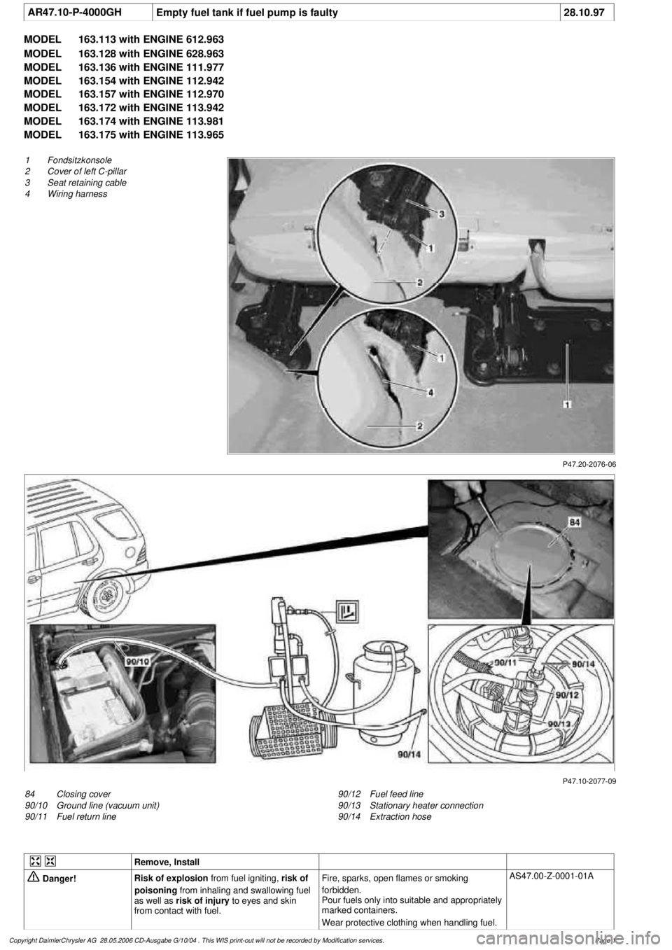
AR47.10-P-4000GH
Empty fuel tank if fuel pump is faulty
28.10.97
MODEL
163.113 with ENGINE 612.963
MODEL
163.128 with ENGINE 628.963
MODEL
163.136 with ENGINE 111.977
MODEL
163.154 with ENGINE 112.942
MODEL
163.157 with ENGINE 112.970
MODEL
163.172 with ENGINE 113.942
MODEL
163.174 with ENGINE 113.981
MODEL
163.175 with ENGINE 113.965
P47.20-2076-06
1
Fondsitzkonsole
2
Cover of left C-pillar
3
Seat retaining cable
4
Wiring harness
P47.10-2077-09
84
Closing cover
90/10
Ground line (vacuum unit)
90/11
Fuel return line
90/12
Fuel feed line
90/13
Stationary heater connection
90/14
Extraction hose
Remove, Install
Danger!
Risk of explosion
from fuel igniting,
risk of
poisoning
from inhaling and swallowing fuel
as well as
risk of injury
to eyes and skin
from contact with fuel.
Fire, sparks, open flames or smoking
forbidden.
Pour fuels only into suitable and appropriately
marked containers.
Wear protective clothing when handling fuel.
AS47.00-Z-0001-01A
Copyright DaimlerChrysler AG 28.05.2006 CD-Ausgabe G/10/04 . This WIS print-out will not be recorde
d by Modification services.
Page 1
Page 2229 of 4133
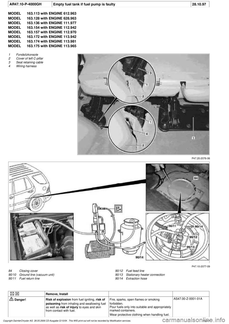
AR47.10-P-4000GH
Empty fuel tank if fuel pump is faulty
28.10.97
MODEL
163.113 with ENGINE 612.963
MODEL
163.128 with ENGINE 628.963
MODEL
163.136 with ENGINE 111.977
MODEL
163.154 with ENGINE 112.942
MODEL
163.157 with ENGINE 112.970
MODEL
163.172 with ENGINE 113.942
MODEL
163.174 with ENGINE 113.981
MODEL
163.175 with ENGINE 113.965
P47.20-2076-06
1
Fondsitzkonsole
2
Cover of left C-pillar
3
Seat retaining cable
4
Wiring harness
P47.10-2077-09
84
Closing cover
90/10
Ground line (vacuum unit)
90/11
Fuel return line
90/12
Fuel feed line
90/13
Stationary heater connection
90/14
Extraction hose
Remove, Install
Danger!
Risk of explosion
from fuel igniting,
risk of
poisoning
from inhaling and swallowing fuel
as well as
risk of injury
to eyes and skin
from contact with fuel.
Fire, sparks, open flames or smoking
forbidden.
Pour fuels only into suitable and appropriately
marked containers.
Wear protective clothing when handling fuel.
AS47.00-Z-0001-01A
Copyright DaimlerChrysler AG 28.05.2006 CD-Ausgabe G/10/04 . This WIS print-out will not be recorde
d by Modification services.
Page 1