run flat MERCEDES-BENZ ML320 1997 Complete Repair Manual
[x] Cancel search | Manufacturer: MERCEDES-BENZ, Model Year: 1997, Model line: ML320, Model: MERCEDES-BENZ ML320 1997Pages: 4133, PDF Size: 88.89 MB
Page 299 of 4133
249 Tires, Wheels
Te ch n ica l
data Instruments
and controlsOperation DrivingInstrument
cluster displayPractical hintsCar care Index Inflating the space-saver tire (ML 55 AMG only)
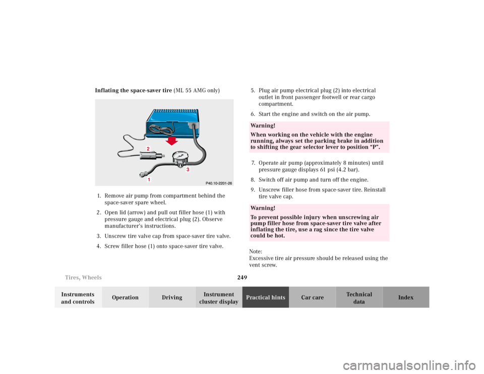
1. Remove air pump from compartment behind the
space-saver spare wheel.
2. Open lid (arrow) and pull out filler hose (1) with
pressure gauge and electrical plug (2). Observe
manufacturer’s instructions.
3. Unscrew tire valve cap from space-saver tire valve.
4. Screw filler hose (1) onto space-saver tire valve.5. Plug air pump electrical plug (2) into electrical
outlet in front passenger footwell or rear cargo
compartment.
6. Start the engine and switch on the air pump.
7. Operate air pump (approximately 8 minutes) until
pressure gauge displays 61 psi (4.2 bar).
8. Switch off air pump and turn off the engine.
9. Unscrew filler hose from space-saver tire. Reinstall
tire valve cap.
Note:
Excessive tire air pressure should be released using the
vent screw.
3
12
Wa r n i n g !
When working on the vehicle with the engine
running, always set the parking brake in addition
to shifting the gear selector lever to position “P”.Wa r n i n g !
To prevent possible injury when unscrewing air
pump filler hose from space-saver tire valve after
inflating the tire, use a rag since the tire valve
could be hot.
Page 360 of 4133
310 Index
Te ch n ica l
data Instruments
and controlsOperation DrivingInstrument
cluster displayPractical hints Car careIndex
Tires
Driving instructions ................................................. 177
Rims and tires ...........................................................288
Rotating wheels ......................................................... 241
Tire inflation pressure .............................................250
Tire replacement .......................................................240
Winter driving instructions .................................... 180
Tow-away alarm ................................................................ 36
Switching off ................................................................ 36
Towing the vehicle .........................................................255
Stranded vehicle .......................................................259
Transmission selector lever, manually unlocking 259
Trailer operation ............................................................ 198
Trailer towing ................................................................. 190
Transmission .................................................................. 165
Transmission control - LOW RANGE mode ...............209
Transmission fluid level ...............................................234
Transmission selector lever, manually unlocking ....259
Traveling abroad ............................................................ 182
Trip computer ................................................................... 83
Trip odometer ................................................................... 80
Trunk ................................................................................. 34
Opening ........................................................................ 28
Trunk lamp ...................................................................... 111Turn signal failure ........................................................... 91
Turn signal lamp, side .................................................. 266
Turn signals ......................................................................90
UUnlocking the vehicle ...................................................... 27VVanity mirrors ................................................................ 113
Vehicle jack .................................................................... 237
Vehicle keys ......................................................................24
Ve h i c l e t o o l s
Screwdriver ............................................................... 237WWarranty coverage ........................................................ 284
Washing the vehicle ..................................................... 280
What you should know at the gas station .................. 212
Wheel bolt wrench ........................................................ 237
Wheels ............................................................................ 240
Changing wheels ...................................................... 245
Page 716 of 4133
249
Tires, Wheels
Te ch n ica l
data
Instruments
and controls Operation Driving
Instrument
cluster display Practical hints
Car care Index
Inflating the space-saver tire
(ML 55 AMG only)
1. Remove air pump from compartment behind the space-saver spare wheel.
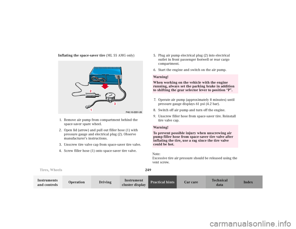
2. Open lid (arrow) and pull out filler hose (1) with pressure gauge and electrical plug (2). Observe
manufacturer’s instructions.
3. Unscrew tire valve cap from space-saver tire valve.
4. Screw filler hose (1) onto space-saver tire valve. 5. Plug air pump electrical plug (2) into electrical
outlet in front passenger footwell or rear cargo
compartment.
6. Start the engine and switch on the air pump.
7. Operate air pump (approximately 8 minutes) until pressure gauge displays 61 psi (4.2 bar).
8. Switch off air pump and turn off the engine.
9. Unscrew filler hose from space-saver tire. Reinstall tire valve cap.
Note:
Excessive tire air pressure should be released using the
vent screw.
3
12
Wa r n i n g !
When working on the vehicle with the engine
running, always set the parking brake in addition
to shifting the gear selector lever to position “P”.Wa r n i n g !
To prevent possible injury when unscrewing air
pump filler hose from space-saver tire valve after
inflating the tire, use a rag since the tire valve
could be hot.
Page 777 of 4133
310
Index
Te ch n ica l
data
Instruments
and controls Operation Driving
Instrument
cluster display Practical hints Car care
Index
Tires Driving instructions ................................................. 177
Rims and tires ...........................................................288
Rotating wheels ......................................................... 241
Tire inflation pressure .............................................250
Tire replacement .......................................................240
Winter driving instructions .................................... 180
Tow-away alarm ................................................................ 36 Switching off ................................................................ 36
Towing the vehicle .........................................................255
Stranded vehicle .......................................................259
Transmission selector lever, manually unlocking 259
Trailer operation ............................................................ 198
Trailer towing ................................................................. 190
Transmission .................................................................. 165
Transmission control - LOW RANGE mode ...............209
Transmission fluid level ...............................................234
Transmission selector lever, manually unlocking ....259
Traveling abroad ............................................................ 182
Trip computer ................................................................... 83
Trip odometer ................................................................... 80
Trunk ................................................................................. 34
Opening ........................................................................ 28
Trunk lamp ...................................................................... 111 Turn signal failure ........................................................... 91
Turn signal lamp, side .................................................. 266
Turn signals ......................................................................90
UUnlocking the vehicle ...................................................... 27VVanity mirrors ................................................................ 113
Vehicle jack .................................................................... 237
Vehicle keys ......................................................................24
Ve h i c l e t o o l s
Screwdriver ............................................................... 237WWarranty coverage ........................................................ 284
Washing the vehicle ..................................................... 280
What you should know at the gas station .................. 212
Wheel bolt wrench ........................................................ 237
Wheels ............................................................................ 240 Changing wheels ...................................................... 245
Page 1840 of 4133
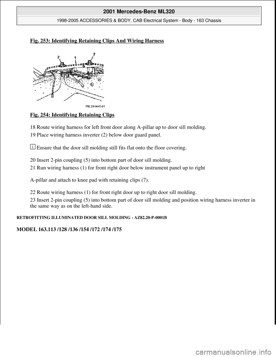
Fig. 253: Identifying Retaining Clips And Wiring Harness
Fig. 254: Identifying Retaining Clips
18 Route wiring harness for left front door along A-pillar up to door sill molding.
19 Place wiring harness inverter (2) below door guard panel.
Ensure that the door sill molding still fits flat onto the floor covering.
20 Insert 2-pin coupling (5) into bottom part of door sill molding.
21 Run wiring harness (1) for front right door below instrument panel up to right
A-pillar and attach to knee pad with retaining clips (7).
22 Route wiring harness (1) for front right door up to right door sill molding.
23 Insert 2-pin coupling (5) into bottom part of door sill molding and position wiring harness inverter in
the same way as on the left-hand side.
RETROFITTING ILLUMINATED DOOR SILL MOLDING - AZ82.20-P-0001B
MODEL 163.113 /128 /136 /154 /172 /174 /175
2001 Mercedes-Benz ML320
1998-2005 ACCESSORIES & BODY, CAB Electrical System - Body - 163 Chassis
me
Saturday, October 02, 2010 3:30:11 PMPage 345 © 2006 Mitchell Repair Information Company, LLC.
Page 2030 of 4133
AR09.41-P-6817MM
Removing and installing charge air cooler
10.11.99
ENGINE
612.963 in MODEL 163.113
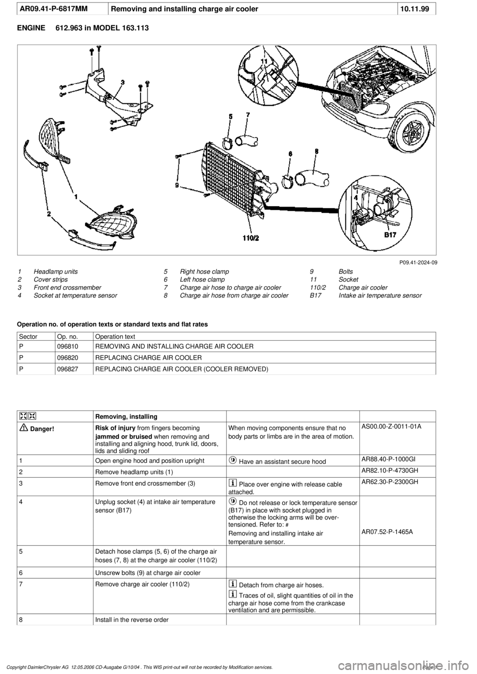
P09.41-2024-09
1
Headlamp units
2
Cover strips
3
Front end crossmember
4
Socket at temperature sensor
9
Bolts
11
Socket
110/2
Charge air cooler
B17
Intake air temperature sensor
5
Right hose clamp
6
Left hose clamp
7
Charge air hose to charge air cooler
8
Charge air hose from charge air cooler
Operation no. of operation texts or standard texts and flat rates
Sector
Op. no.
Operation text
P
096810
REMOVING AND INSTALLING CHARGE AIR COOLER
P
096820
REPLACING CHARGE AIR COOLER
P
096827
REPLACING CHARGE AIR COOLER (COOLER REMOVED)
Removing, installing
Danger!
Risk of injury
from fingers becoming
jammed or bruised
when removing and
installing and aligning hood, trunk lid, doors,
lids and sliding roof
When moving components ensure that no
body parts or limbs are in the area of motion.
AS00.00-Z-0011-01A
1
Open engine hood and position upright
Have an assistant secure hood
AR88.40-P-1000GI
2
Remove headlamp units (1)
AR82.10-P-4730GH
3
Remove front end crossmember (3)
Place over engine with release cable
attached.
AR62.30-P-2300GH
4
Unplug socket (4) at intake air temperature
sensor (B17)
Do not release or lock temperature sensor
(B17) in place with socket plugged in
otherwise the locking arms will be over-
tensioned. Refer to:
#
Removing and installing intake air
temperature sensor.
AR07.52-P-1465A
5
Detach hose clamps (5, 6) of the charge air
hoses (7, 8) at the charge air cooler (110/2)
6
Unscrew bolts (9) at charge air cooler
7
Remove charge air cooler (110/2)
Detach from charge air hoses.
Traces of oil, slight quantities of oil in the
charge air hose come from the crankcase
ventilation and are permissible.
8
Install in the reverse order
Copyright DaimlerChrysler AG 12.05.2006 CD-Ausgabe G/10/04 . This WIS print-out will not be recorde
d by Modification services.
Page 1
Page 2032 of 4133
AR09.41-P-6817MM
Removing and installing charge air cooler
10.11.99
ENGINE
612.963 in MODEL 163.113
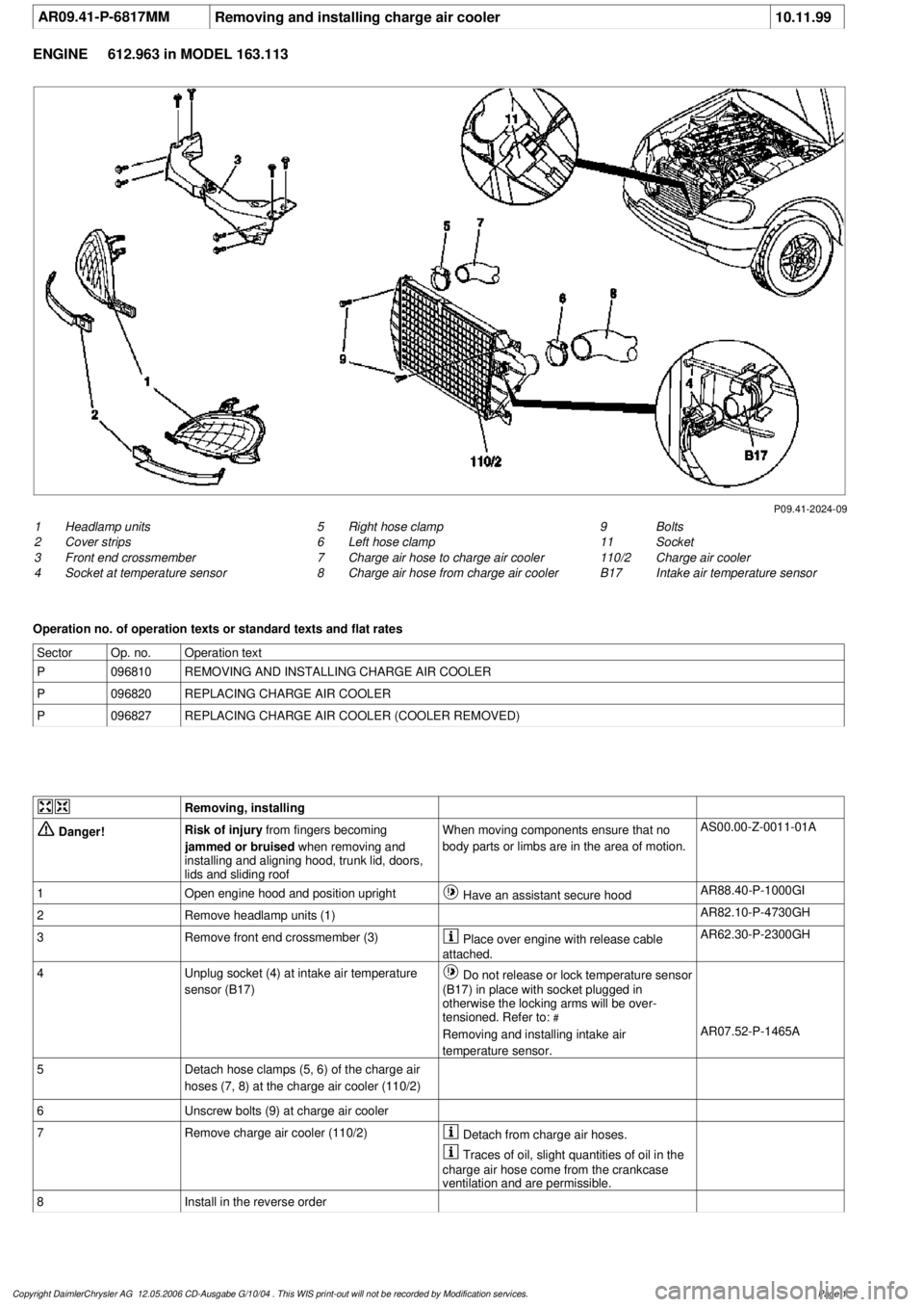
P09.41-2024-09
1
Headlamp units
2
Cover strips
3
Front end crossmember
4
Socket at temperature sensor
9
Bolts
11
Socket
110/2
Charge air cooler
B17
Intake air temperature sensor
5
Right hose clamp
6
Left hose clamp
7
Charge air hose to charge air cooler
8
Charge air hose from charge air cooler
Operation no. of operation texts or standard texts and flat rates
Sector
Op. no.
Operation text
P
096810
REMOVING AND INSTALLING CHARGE AIR COOLER
P
096820
REPLACING CHARGE AIR COOLER
P
096827
REPLACING CHARGE AIR COOLER (COOLER REMOVED)
Removing, installing
Danger!
Risk of injury
from fingers becoming
jammed or bruised
when removing and
installing and aligning hood, trunk lid, doors,
lids and sliding roof
When moving components ensure that no
body parts or limbs are in the area of motion.
AS00.00-Z-0011-01A
1
Open engine hood and position upright
Have an assistant secure hood
AR88.40-P-1000GI
2
Remove headlamp units (1)
AR82.10-P-4730GH
3
Remove front end crossmember (3)
Place over engine with release cable
attached.
AR62.30-P-2300GH
4
Unplug socket (4) at intake air temperature
sensor (B17)
Do not release or lock temperature sensor
(B17) in place with socket plugged in
otherwise the locking arms will be over-
tensioned. Refer to:
#
Removing and installing intake air
temperature sensor.
AR07.52-P-1465A
5
Detach hose clamps (5, 6) of the charge air
hoses (7, 8) at the charge air cooler (110/2)
6
Unscrew bolts (9) at charge air cooler
7
Remove charge air cooler (110/2)
Detach from charge air hoses.
Traces of oil, slight quantities of oil in the
charge air hose come from the crankcase
ventilation and are permissible.
8
Install in the reverse order
Copyright DaimlerChrysler AG 12.05.2006 CD-Ausgabe G/10/04 . This WIS print-out will not be recorde
d by Modification services.
Page 1
Page 2089 of 4133

29
Slacken cylinder head bolts (21) in stages,
unscrew
Loosen cylinder head bolts according to
loosening schematic only after engine has
cooled down to prevent cylinder head from
distorting.
AR01.30-P-5800-09B
Installation:
Observe tightening pattern
and tightening instructions of cylinder head
bolts.
Oil thread and head contact surface of
cylinder head bolts.
AR01.30-P-5800-07B
Screwdriver insert
*000589031000
Screwdriver insert
*000589041000
*BA01.30-P-1001-01D
30
Remove cylinder head
Installation:
On Engine 112/113 observe
porous points in the left and right cylinder
head. If porous points are present, sealant
must be applied to the cylinder head gasket.
Notes on application of sealant to cylinder
head gasket.
Engine 112, 113
AH01.30-P-1000-04VA
The sealant must be applied within
10 minutes.
Loctite 5900 sealant.
*BR00.45-Z-1015-01A
31
Inspect version of cylinder head gasket
Assignment of cylinder head gasket
Information for assigning the cylinder head
gaskets
Engine 112, 113
AH01.30-P-1000-06V
32
Check cylinder head bolts (21)
AR01.30-P-5800-03B
*BE01.30-P-1001-04B
33
Clean sealing surfaces, inspect for cracks,
shrink holes and flatness, clean threaded
holes.
Pay attention to dowel sleeves (26) for
locating the cylinder head.
Sealing surfaces of crankcase and
cylinder head are provided with an 0.8 mm
thick silicone layer during series production.
At the time of repair installation, silicone
sealant is applied to the sealing area only in
case of any shrink holes.
The sealant must be applied within
10 minutes.
Loctite 5900 sealant.
*BR00.45-Z-1015-01A
34
Install in the reverse order
Danger!
Risk of accident
caused by vehicle starting
off by itself when engine is running.
Risk of
injury
caused by contusions and burns when
working in engine during starting procedure
Secure vehicle to prevent it from moving.
Wear closed and snug-fitting work clothes.
Do not grasp hot or rotating parts.
AS00.00-Z-0005-01A
35
Run engine and inspect for leaks
36
Inspect cooling system for leaks
Warm up engine to operating temperature
and then inspect cooling system or leaks.
AR20.00-P-1010HA
37
Read out and erase fault memory
Stored faults which can result from cables
being disconnected or from simulation during
removal and installation or test work, have to
be processed and erased in the fault
memories after completing the work:
#
Diagnosis Manual Volume 2 Index 0:
Connecting and using test equipment.
Cylinder head/cylinder head bolts
Number
Designation
Engine
112.910/911/912/
913/914/915/
916/917/920/
921/922/923/
940/941/942/
943/944/945/
946/947/949/
951/953/954/
955/960/961/
970/972/973/975
Engine
113.940/941/
942/943/944/
945/946/948/
960/961/962/
963/965/966/
967/968/969/
980/981/982/
984/986/987/
988/990/991/
992/993
BE01.30-P-1001-04B
Cylinder head bolt
Thread diameter
M
1111
Length (L) when new
mm
141.5141.5
Length (L)
mm
T
144.5
T
144.5
Copyright DaimlerChrysler AG 20.05.2006 CD-Ausgabe G/10/04 . This WIS print-out will not be recorde
d by Modification services.
Page 5
Page 2097 of 4133

29
Slacken cylinder head bolts (21) in stages,
unscrew
Loosen cylinder head bolts according to
loosening schematic only after engine has
cooled down to prevent cylinder head from
distorting.
AR01.30-P-5800-09B
Installation:
Observe tightening pattern
and tightening instructions of cylinder head
bolts.
Oil thread and head contact surface of
cylinder head bolts.
AR01.30-P-5800-07B
Screwdriver insert
*000589031000
Screwdriver insert
*000589041000
*BA01.30-P-1001-01D
30
Remove cylinder head
Installation:
On Engine 112/113 observe
porous points in the left and right cylinder
head. If porous points are present, sealant
must be applied to the cylinder head gasket.
Notes on application of sealant to cylinder
head gasket.
Engine 112, 113
AH01.30-P-1000-04VA
The sealant must be applied within
10 minutes.
Loctite 5900 sealant.
*BR00.45-Z-1015-01A
31
Inspect version of cylinder head gasket
Assignment of cylinder head gasket
Information for assigning the cylinder head
gaskets
Engine 112, 113
AH01.30-P-1000-06V
32
Check cylinder head bolts (21)
AR01.30-P-5800-03B
*BE01.30-P-1001-04B
33
Clean sealing surfaces, inspect for cracks,
shrink holes and flatness, clean threaded
holes.
Pay attention to dowel sleeves (26) for
locating the cylinder head.
Sealing surfaces of crankcase and
cylinder head are provided with an 0.8 mm
thick silicone layer during series production.
At the time of repair installation, silicone
sealant is applied to the sealing area only in
case of any shrink holes.
The sealant must be applied within
10 minutes.
Loctite 5900 sealant.
*BR00.45-Z-1015-01A
34
Install in the reverse order
Danger!
Risk of accident
caused by vehicle starting
off by itself when engine is running.
Risk of
injury
caused by contusions and burns when
working in engine during starting procedure
Secure vehicle to prevent it from moving.
Wear closed and snug-fitting work clothes.
Do not grasp hot or rotating parts.
AS00.00-Z-0005-01A
35
Run engine and inspect for leaks
36
Inspect cooling system for leaks
Warm up engine to operating temperature
and then inspect cooling system or leaks.
AR20.00-P-1010HA
37
Read out and erase fault memory
Stored faults which can result from cables
being disconnected or from simulation during
removal and installation or test work, have to
be processed and erased in the fault
memories after completing the work:
#
Diagnosis Manual Volume 2 Index 0:
Connecting and using test equipment.
Cylinder head/cylinder head bolts
Number
Designation
Engine
112.910/911/912/
913/914/915/
916/917/920/
921/922/923/
940/941/942/
943/944/945/
946/947/949/
951/953/954/
955/960/961/
970/972/973/975
Engine
113.940/941/
942/943/944/
945/946/948/
960/961/962/
963/965/966/
967/968/969/
980/981/982/
984/986/987/
988/990/991/
992/993
BE01.30-P-1001-04B
Cylinder head bolt
Thread diameter
M
1111
Length (L) when new
mm
141.5141.5
Length (L)
mm
T
144.5
T
144.5
Copyright DaimlerChrysler AG 20.05.2006 CD-Ausgabe G/10/04 . This WIS print-out will not be recorde
d by Modification services.
Page 5
Page 2591 of 4133
AR47.20-P-1070M
Removing and installing fuel full-flow filter
24.8.99
ENGINE
612.963 in MODEL 163.113
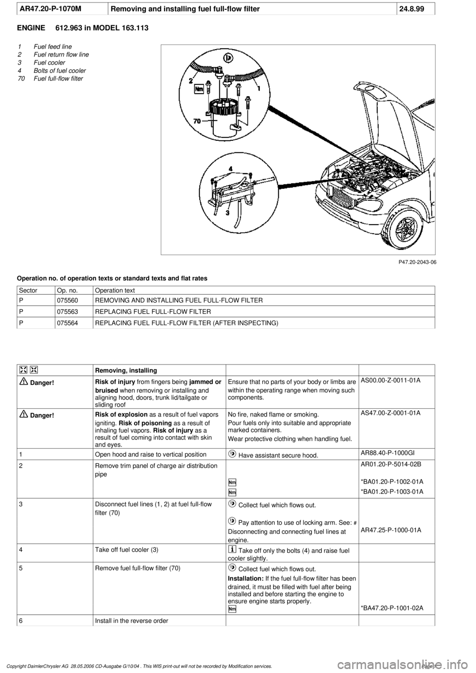
P47.20-2043-06
1
Fuel feed line
2
Fuel return flow line
3
Fuel cooler
4
Bolts of fuel cooler
70
Fuel full-flow filter
Operation no. of operation texts or standard texts and flat rates
Sector
Op. no.
Operation text
P
075560
REMOVING AND INSTALLING FUEL FULL-FLOW FILTER
P
075563
REPLACING FUEL FULL-FLOW FILTER
P
075564
REPLACING FUEL FULL-FLOW FILTER (AFTER INSPECTING)
Removing, installing
Danger!
Risk of injury
from fingers being
jammed or
bruised
when removing or installing and
aligning hood, doors, trunk lid/tailgate or
sliding roof
Ensure that no parts of your body or limbs are
within the operating range when moving such
components.
AS00.00-Z-0011-01A
Danger!
Risk of explosion
as a result of fuel vapors
igniting.
Risk of poisoning
as a result of
inhaling fuel vapors.
Risk of injury
as a
result of fuel coming into contact with skin
and eyes.
No fire, naked flame or smoking.
Pour fuels only into suitable and appropriate
marked containers.
Wear protective clothing when handling fuel.
AS47.00-Z-0001-01A
1
Open hood and raise to vertical position
Have assistant secure hood.
AR88.40-P-1000GI
2
Remove trim panel of charge air distribution
pipe
AR01.20-P-5014-02B
*BA01.20-P-1002-01A
*BA01.20-P-1003-01A
3
Disconnect fuel lines (1, 2) at fuel full-flow
filter (70)
Collect fuel which flows out.
Pay attention to use of locking arm. See:
#
Disconnecting and connecting fuel lines at
engine.
AR47.25-P-1000-01A
4
Take off fuel cooler (3)
Take off only the bolts (4) and raise fuel
cooler slightly.
5
Remove fuel full-flow filter (70)
Collect fuel which flows out.
Installation:
If the fuel full-flow filter has been
drained, it must be filled with fuel after being
installed and before starting the engine to
ensure engine starts properly.
*BA47.20-P-1001-02A
6
Install in the reverse order
Copyright DaimlerChrysler AG 28.05.2006 CD-Ausgabe G/10/04 . This WIS print-out will not be recorde
d by Modification services.
Page 1