engine coolant MERCEDES-BENZ ML350 1997 Complete Repair Manual
[x] Cancel search | Manufacturer: MERCEDES-BENZ, Model Year: 1997, Model line: ML350, Model: MERCEDES-BENZ ML350 1997Pages: 4133, PDF Size: 88.89 MB
Page 3771 of 4133
AR20.00-P-1250B
Remove oil from cooling and heating system
22.7.97
ENGINE
611.960 in MODEL 202.134 /193 /194 /133
ENGINE
611.961 in MODEL 210.006 /206 /007 /606
ENGINE
611.962 in MODEL 203.006 /004 /206 /204 /706
ENGINE
612.961 in MODEL 210.616 /216 /016
ENGINE
612.962 in MODEL 203.016 /216
ENGINE
612.963 in MODEL 163.113
ENGINE
613.960 in MODEL 220.026
ENGINE
613.961 in MODEL 210.026 /226
ENGINE
628.960 in MODEL 220.028 /128
ENGINE
628.961 in MODEL 211.028
ENGINE
628.963 in MODEL 163.128
ENGINE
646.951 in MODEL 211.004
ENGINE
646.961 in MODEL 211.006 /206 /606
ENGINE
647.961 in MODEL 211.016 /216 /616
ENGINE
648.961 in MODEL 211.023 /026 /223 /226
ENGINE
612.967 in MODEL 209.316
ENGINE
612.990 in MODEL 203.018 /218 /718
ENGINE
646.962 in MODEL 203.007 /207 /707
ENGINE
646.963 in MODEL 203.008 /208 /708
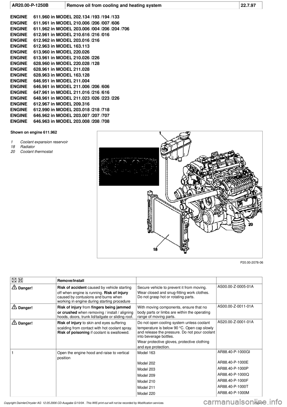
P20.00-2078-06
Shown on engine 611.962
1
Coolant expansion reservoir
18
Radiator
20
Coolant thermostat
Remove/Install
Danger!
Risk of accident
caused by vehicle starting
off when engine is running.
Risk of injury
caused by contusions and burns when
working in engine during starting procedure
Secure vehicle to prevent it from moving.
Wear closed and snug-fitting work clothes.
Do not grasp hot or rotating parts.
AS00.00-Z-0005-01A
Danger!
Risk of injury
from
fingers being jammed
or crushed
when removing / install / aligning
hoods, doors, trunk lid/tailgate or sliding roof.
With moving components, ensure that no
body parts or limbs are within the operating
range of moving parts.
AS00.00-Z-0011-01A
Danger!
Risk of injury
to skin and eyes suffering
scalding from contact with hot coolant spray.
Risk of poisoning
if coolant is swallowed.
Do not open cooling system unless coolant
temperature is below 90 °C. Open cap slowly
and release the pressure. Do not pour coolant
into beverage bottles.
Wear protective gloves, protective clothing
and eye protection.
AS20.00-Z-0001-01A
1
Open the engine hood and raise to vertical
position
Model 163
AR88.40-P-1000GI
Model 202
AR88.40-P-1000E
Model 203
AR88.40-P-1000P
Model 209
AR88.40-P-1000Q
Model 210
AR88.40-P-1000F
Model 211
AR88.40-P-1000T
Model 220
AR88.40-P-1000M
Copyright DaimlerChrysler AG 12.05.2006 CD-Ausgabe G/10/04 . This WIS print-out will not be recorde
d by Modification services.
Page 1
Page 3772 of 4133

2
Drain the coolant
Engine 611.960/961/962,
612.961/962/967/990, 613.960/961,
628.960/961/963, 646, 647, 648
AR20.00-P-1142HB
Engine 612.963
AR20.00-P-1142M
3
Remove coolant thermostat (20)
Engine 611, 612, 613, 646, 647, 648
AR20.10-P-2460PP
Engine 628.960/963
AR20.10-P-2460M
4
Mount the housing to remove oil and flush the
cooling/heating system
The housing may be used only for the
purpose of removing the oil, and must be
removed again after it has been rinsed.
Engine 611.960/961/962/ 612.961/962
/963/967/990, 613.960/961
*BA20.10-P-1005-01A
Engine 628.960/961/962/963
*BA20.10-P-1002-01F
Engine 646.962/963
*BA20.10-P-1002-01G
y
Housing for removing oil and flushing the
cooling/heating system
WF58.50-P-2000-01A
Cleaning
5
Set the heater control to full power
6
Set the auxiliary heater to full power
7
Fill the cooling/heating system with a rinsing
solution
Rinsing solution consisting of 5% cleaning
agent and 95% water.
*BF20.00-P-1001-02E
Cleaning agent
*BR00.45-Z-1001-04A
8
Warm up the engine to operating temperature
at moderate engine speed
While engine is running, hold operating
temperature at 80 °C for about 5 min.
9
Switch off engine and allow the cooling
system to
cool to about 50 °C
10
Drain the rinsing solution completely at the
drain plug of radiator (18)
Observe the environmental instructions of
the manufacturer of the cleaning agent.
11
Fill cooling system with fresh water
Pour fresh water into the coolant
expansion reservoir (1).
12
Warm up the engine to operating temperature
at moderate engine speed
While engine is running, hold the
operating temperature at 80 °C for about
5 min.
13
Drain the fresh water completely at the drain
plug of radiator (18)
Repeat the flushing process until all of the
rinsing solution has been removed.
14
Install in the reverse order
Coolant pump, coolant thermostat
Number
Designation
Engine
611.960/
961
Engine
611.962
Engine
612.961/
963
Engine
612.962/
967/990
BA20.10-P-1005-01A
Bolt of coolant thermostat housing to cylinder head
Nm
9999
Designation
Engine
613.960/
961
BA20.10-P-1005-01A
Bolt of coolant thermostat housing to cylinder head
Nm
9
Designation
Engine
628.960/961/962/
963
Copyright DaimlerChrysler AG 12.05.2006 CD-Ausgabe G/10/04 . This WIS print-out will not be recorde
d by Modification services.
Page 2
Page 3773 of 4133

BA20.10-P-1002-01F
Bolt of coolant thermostat housing to
crankcase
Nm
9
Designation
Engine
647, 648
Engine
646.951/
961
Engine
646.962/
963
BA20.10-P-1002-01G
Bolt of coolant thermostat housing to cylinder head
Nm
999
Designation
Engine
611.960
Engine
611.961
Engine
611.962
BF20.00-P-1001-02E
Cooling system
Total capacity
Liters
8.0
Y
10.3
Y
11.9
Capacity of anticorrosion/
antifreeze agent down to
-37 °C
Liters
4.0
Y
5.2
Y
6.0
Capacity of anticorrosion/
antifreeze agent down to
-45 °C
Liters
4.5
Y
5.7
Y
6.5
Specifications for Operating
Fluids
SheetBB00.40-P-0310-01ABB00.40-P-0310-01ABB00.40-P-0310-01A
SheetBB00.40-P-0325-00ABB00.40-P-0325-00ABB00.40-P-0325-00A
Cooling system
Number
Designation
Engine
612.961
Engine
612.962/ 967
Engine
612.963
BF20.00-P-1001-02E
Cooling system
Total capacity
Liters
Y
10.6
Y
12.4
Y
11.0
Capacity of anticorrosion/
antifreeze agent down to
-37 °C
Liters
Y
5.3
Y
6.2
Y
5.5
Capacity of anticorrosion/
antifreeze agent down to
-45 °C
Liters
Y
5.8
Y
6.8
Y
6.25
Specifications for Operating
Fluids
SheetBB00.40-P-0310-01ABB00.40-P-0310-01ABB00.40-P-0310-01A
SheetBB00.40-P-0325-00ABB00.40-P-0325-00ABB00.40-P-0325-00A
Cooling system
Number
Designation
Engine
613.960
Engine
613.961
Engine
628.960
BF20.00-P-1001-02E
Cooling system
Total capacity
Liters
Y
15.5
Y
11.2
Y
16.5
Capacity of anticorrosion/
antifreeze agent down to
-37 °C
Liters
Y
7.75
Y
5.6
Y
8.25
Capacity of anticorrosion/
antifreeze agent down to
-45 °C
Liters
Y
8.0
Y
6.2
Y
9.1
Specifications for Operating
Fluids
SheetBB00.40-P-0310-01ABB00.40-P-0310-01ABB00.40-P-0310-01A
SheetBB00.40-P-0325-00ABB00.40-P-0325-00ABB00.40-P-0325-00A
Copyright DaimlerChrysler AG 12.05.2006 CD-Ausgabe G/10/04 . This WIS print-out will not be recorde
d by Modification services.
Page 3
Page 3835 of 4133

SI18.00-P-0010A
Service Information: oil sludge
26.3.01
ENGINE
111 in MODELS 124, 163, 170, 202, 203, 208, 210
ENGINE
112 in MODELS 129, 163, 170, 202, 203, 208, 210, 220
ENGINE
112, 113 in MODEL 463
ENGINE
113 in MODELS 129, 163, 202, 208, 210, 215, 220
ENGINE
137 in MODEL 215, 220
ENGINE
166 in MODEL 168
Oil sludging in gasoline engines with ASSYST maintenance
system
Recently we have determined that time and time again oil
sludging occurs in gasoline engines with an ASSYST maintenance
system.
Oil sludging can lead to the following complaints:
D
engine oil consumption
D
engine smoke (white/blue)
D
influencing of oil level indicator
D
clogged oil filter, engine oil thickened like jelly
D
Check engine lamp illuminated
D
oil sludge visible during assembly job, e.g. in oil filter, in cylinder
head covers, condensation sludging
(engine 166) etc.
-----------------------------------------------------------------------------------------
The following list of causes may lead individually or as a combination
to engine oil sludging:
D
Crankcase ventilation inoperable, function orifices, bores,
passages in cylinder head cover, cylinder head, crankcase etc.
are mechanically sealed. A nonfunctioning crankcase
ventilation boosts loads on the engine oil through organic
nitrates. The risk of oil sludging increases.
The mechanical condition of the engine is always to be
checked, i.e. all engine oil drain orifices on the cylinder head
and crankcase and all crankcase ventilation ducts must be free
of obstacles. Crankcase breather lines may not be kinked.
Check the ventilation bores in the cylinder head covers.
-----------------------------------------------------------------------------------------
D
The engine oil used does not comply with the specifications in
Sheet 229.1 or 229.3 of the Specifications for Service Products.
The additive process, e.g. dirt-carrying capability, neutralization
capability and oxidation resistance as well as the quality of the
base stock influence sludging time.
Use of engine oils with best possible resistance to formation of
sludge, i.e. use only tested and approved engine oils (from
Sheet 229.1 or 229.3). The best protection is afforded by the
engine oils on Sheet 229.3, which fulfill more stringent
specifications with regard to preventing sludge and deposits
(see Sheet 221.0, page 11). These oils have a distinctly better
anti-sludge characteristic than other engine oils.
D
Sludging after adding a fuel or engine oil special additive.
Do not use fuel or engine oil special additives. More information
hereto is available on Sheet 219.0 of the Specifications for
Service products. Reference to customer not to use special
additives.
D
Engine oil change not performed according to ASSYST
specifications. At driven distances
exceeding > approx. 3000 km, engine oil sludging may occur.
-----------------------------------------------------------------------------------------
Comply with engine oil and filter change as under ASSYST
specifications. Observe remaining distance.
D
Fuel grade lies outside standard (regionally contingent). If
contaminated, deficient fuel is used, then engine oil sludging
may occur even where approved engine oil is used.
Operation with fuel, e.g. as under DIN EN 228. Clarify refueling
behavior of customer. If engine operation regional, is
temporarily possible with deficient oil only, then the startup
distance has to be individually reduced, i.e. the oil change
temporarily performed at an interval of, e.g. 10,000 km.
D
Radiator antifreeze penetration into engine oil, e.g. through an
internal engine leak (cylinder head gasket, casting porosity).
The engine oil sludges within a short period. The crankcase
ventilation clogs up and stops functioning. Condensation
sludging clogs up the oil separator cells
(engine 166).
Rectify coolant leakage. Clean all sludged engine parts, in
particular the crankcase ventilation parts. If the occurrence
repeats, and casting porosity is suspected, e.g. replace
crankcase.
-----------------------------------------------------------------------------------------
Copyright DaimlerChrysler AG 20.05.2006 CD-Ausgabe G/10/04 . This WIS print-out will not be recorde
d by Modification services.
Page 1
Page 3842 of 4133
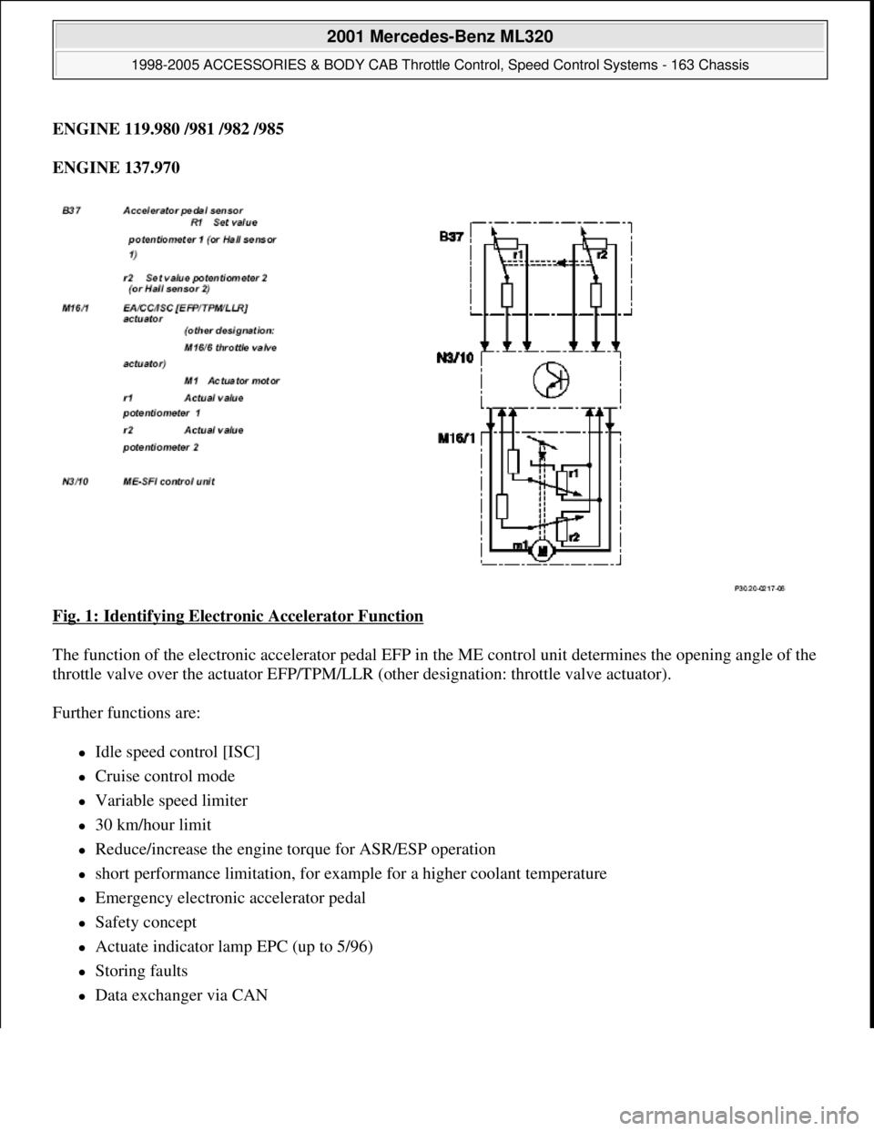
ENGINE 119.980 /981 /982 /985
ENGINE 137.970
Fig. 1: Identifying Electronic Accelerator Function
The function of the electronic accelerator pedal EFP in the ME control unit determines the opening angle of the
throttle valve over the actuator EFP/TPM/LLR (other designation: throttle valve actuator).
Further functions are:
Idle speed control [ISC]
Cruise control mode
Variable speed limiter
30 km/hour limit
Reduce/increase the engine torque for ASR/ESP operation
short performance limitation, for example for a higher coolant temperature
Emergency electronic accelerator pedal
Safety concept
Actuate indicator lamp EPC (up to 5/96)
Storing faults
Data exchanger via CAN
2001 Mercedes-Benz ML320
1998-2005 ACCESSORIES & BODY CAB Throttle Control, Speed Control Systems - 163 Chassis
me
Saturday, October 02, 2010 3:36:27 PMPage 2 © 2006 Mitchell Repair Information Company, LLC.
Page 3857 of 4133
different engine loads, e.g. power steering turned to full lock, engaging drive mode, switching on AC
compressor
different mixture, e.g. from activated charcoal canister if purging activated (depending on activated
charcoal charge)
Function
The actuator EFP/TPM/LLR (additional designation: throttle valve actuator) regulates the idling speed by
changing the throttle valve position. It is actuated by the ME-SFI control unit.
The ME-SFI control unit actuates the throttle valve motor (M16/1 m1) in line with the input signals received at
the ME-SFI control unit (N3/10).
Heating speed of the catalytic converter
In order to warm up the catalytic converter more rapidly to operating temperature, engine speed is increased in
the idle speed range to 1100 up to 1500 rpm for about 20 seconds after each starting procedure at coolant
temperatures of < 40 °C. When a Drive position is engaged, engine speed is immediately controlled to a lower
value.
Automatic transmission
When a drive position is engaged, a lower engine speed is controlled in order to reduce the creeping tendency o
f
the vehicle. The information "Drive position engaged/not engaged" is transmitted by the ETC control unit
(N15/3) over the CAN databus to the ME-SFI control unit.
Ignition angle
To assist the idle speed control, the ignition angle can be retarded by as much as 36° crank angle or advanced by
as much as 20° crank angle from the calculated specified value.
The control in the idle speed range by altering the ignition angle reacts more rapidly than altering the position o
f
the throttle valve.
The idling speed can be influenced with HHT or the STAR DIAGNOSIS.
AC compressor
In order to avoid engine speed dropping in the idle speed range when the AC compressor is engaged, the AC
push-button control unit (N19) or automatic air conditioning push-button control unit (N22) supplies a signal to
the ME-SFI control unit (as of approx. 6/96 over CAN) and the opening cross-section of the throttle valve is
enlarged.
When the air conditionin
g unit is switched on and the external temperature exceeds 35° C the idling speed on
2001 Mercedes-Benz ML320
1998-2005 ACCESSORIES & BODY CAB Throttle Control, Speed Control Systems - 163 Chassis
me
Saturday, October 02, 2010 3:36:27 PMPage 17 © 2006 Mitchell Repair Information Company, LLC.
Page 3858 of 4133
vehicles delivered from 6/00 is increased for the driving mode selected by about 100 rpm when the switch-on
threshold of about 900 rpm is exceeded. This increase is cancelled again when the external temperature drops
below 32° C.
Undervoltage
If the engine control unit detects an undervoltage the idling speed is increased until the ignition is switched off
for the driving mode selected by about 100 rpm.
If the control unit SBC reports an undervoltage to the engine control unit over CAN the idling speed for the
driving mode selected is increased to about 750 rpm.
Motor electronics control unit, location/task/
design/function GF07.61-P-
5000F
ME-SFI ignition system function GF15.12-P-
0001F
ECI ignition system functionEngine 137GF15.15-P-
3000L
Pedal value sensor, location/task/design/ function GF30.20-P-
4011L
Coolant temperature sensor, location/task/
design/function
Engine 119, 120GF07.04-P-
5026F
Engine 104, 111GF07.04-P-
5026G
Engine 112, 113, 137GF07.04-P-
5026A
Intake air temperature sensor, location/task/
design/function GF07.04-P-
2100F
ME fuel supply function
Engine 104, 111, 119, 120 in Model 129,
140, 170, 202, 208, 210GF07.61-P-
3004F
Engine 112, 113, 137 (except in Model
203, 209, 211)GF07.61-P-
3004A
Engine 112.91/94/95 203
Engine 112.91/94/95, 113.96 in Model
211
Engine 112.912/955, 113.968 in Model
209
GF07.61-P-
3004P
Crankshaft position sensor, location/task/
design/function GF07.04-P-
4116F
Electronic accelerator/cruise control/idle speed
control actuator location/task/design/function GF30.22-P-
4010F
Electronic accelerator pedal emergency running
mode functionEngine 120.98GF30.20-P-
4026F
Engine 104, 111, 112, 113, 119, 137GF30.20-P-
4026E
2001 Mercedes-Benz ML320
1998-2005 ACCESSORIES & BODY CAB Throttle Control, Speed Control Systems - 163 Chassis
me
Saturday, October 02, 2010 3:36:27 PMPage 18 © 2006 Mitchell Repair Information Company, LLC.
Page 3861 of 4133
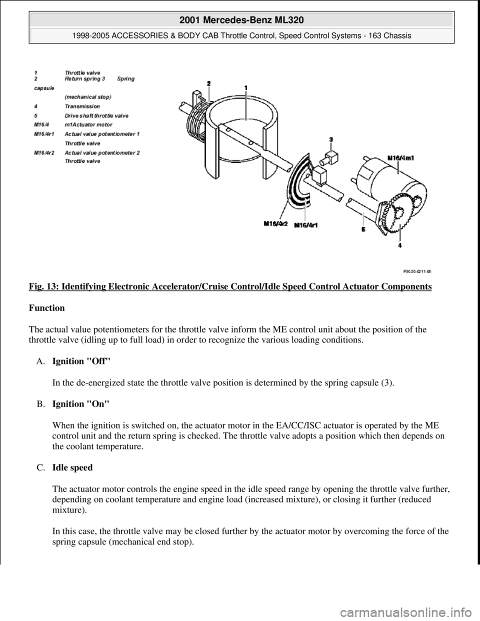
Fig. 13: Identifying Electronic Accelerator/Cruise Control/Idle Speed Control Actuator Components
Function
The actual value potentiometers for the throttle valve inform the ME control unit about the position of the
throttle valve (idling up to full load) in order to recognize the various loading conditions.
A.Ignition "Off"
In the de-energized state the throttle valve position is determined by the spring capsule (3).
B.Ignition "On"
When the ignition is switched on, the actuator motor in the EA/CC/ISC actuator is operated by the ME
control unit and the return spring is checked. The throttle valve adopts a position which then depends on
the coolant temperature.
C.Idle speed
The actuator motor controls the engine speed in the idle speed range by opening the throttle valve further,
depending on coolant temperature and engine load (increased mixture), or closing it further (reduced
mixture).
In this case, the throttle valve may be closed further by the actuator motor by overcoming the force of the
sprin
g capsule (mechanical end stop).
2001 Mercedes-Benz ML320
1998-2005 ACCESSORIES & BODY CAB Throttle Control, Speed Control Systems - 163 Chassis
me
Saturday, October 02, 2010 3:36:27 PMPage 21 © 2006 Mitchell Repair Information Company, LLC.
Page 3961 of 4133

AD54.30-P-5000-02A
Display instruments controlled via CAN
troubleshooting chart IC
The following display instruments or indicator lamps/ malfunction
indicator lamps receive their information from the traction system
control module (N47) via CAN data buses (an appropriate message
appears in the display on vehicles with multi-function display):
D
Total mileage recorder, trip odometer
D
Electronic speedometer
D
Low brake fluid level/parking brake indicator lamp (except model 163
parking brake indicator lamp only via CAN)
D
Brake pad wear indicator lamp
D
ABS MIL
D
ETS, ASR, ESP indicator lamp
D
ETS, ASR, ESP malfunction indicator lamp
Model 163 only:
The
"Low-Range"
indicator lamp receives its information from the
transfer case control module (N78) via CAN data buses.
The
"Fog lamps"
indicator lamp (only model 163 except
I
) receives
its information from the All-activity module (AAM, N10) via CAN data
buses.
Model 168 only:
The
" Gear indicator "
indicator lamp receives its information from the
gear recognition module (A61) or from automatic clutch control module
(N15/4) via CAN data buses.
The following display instruments or indicator lamps/
malfunction indicator lamps receive their information from the
injection system control module (N3) via CAN data buses (an
appropriate message appears in the display on vehicles with
multi-function display):
D
Tachometer
D
Low engine oil level lamp
D
Engine coolant temperature
D
Preglow indicator lamp (diesel only)
D
Vehicle speed warning
D
Vehicle speed limit warning
D
Severe leak warning (
I
only), the fuel reserve indicator lamp
(A1e4) flashes
D
Active Service System (ASSYST):
D
Oil condition
D
Oil level
D
Oil temperature
D
Mass volumetric efficiency (load moment)
D
Engine speed, engine coolant temperature
Copyright DaimlerChrysler AG 05.06.2006 CD-Ausgabe G/10/04 . This WIS print-out will not be recorde
d by Modification services.
Page 1
Page 3986 of 4133
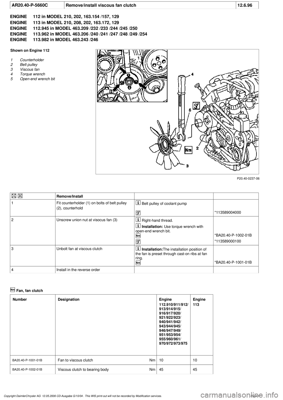
AR20.40-P-5660C
Remove/install viscous fan clutch
12.6.96
ENGINE
112 in MODEL 210, 202, 163.154 /157, 129
ENGINE
113 in MODEL 210, 208, 202, 163.172, 129
ENGINE
112.945 in MODEL 463.209 /232 /233 /244 /245 /250
ENGINE
113.962 in MODEL 463.206 /240 /241 /247 /248 /249 /254
ENGINE
113.982 in MODEL 463.243 /246
P20.40-0237-06
Shown on Engine 112
1
Counterholder
2
Belt pulley
3
Viscous fan
4
Torque wrench
5
Open-end wrench bit
Remove/Install
1
Fit counterholder (1) on bolts of belt pulley
(2), counterhold
Belt pulley of coolant pump
*113589004000
2
Unscrew union nut at visocus fan (3)
Right-hand thread.
Installation:
Use torque wrench with
open-end wrench bit.
*BA20.40-P-1002-01B
*113589000100
3
Unbolt fan at viscous clutch
Installation:
The installation position of
the fan is preset through cast-on ribs at fan
ring.
*BA20.40-P-1001-01B
4
Install in the reverse order
Fan, fan clutch
Number
Designation
Engine
112.910/911/912/
913/914/915/
916/917/920/
921/922/923/
940/941/942/
943/944/945/
946/947/949/
951/953/954/
955/960/961/
970/972/973/975
Engine
113
BA20.40-P-1001-01B
Fan to viscous clutch
Nm
1010
BA20.40-P-1002-01B
Viscous clutch to bearing body
Nm
4545
Copyright DaimlerChrysler AG 12.05.2006 CD-Ausgabe G/10/04 . This WIS print-out will not be recorde
d by Modification services.
Page 1