height adjustment MERCEDES-BENZ ML350 1997 Complete Owner's Manual
[x] Cancel search | Manufacturer: MERCEDES-BENZ, Model Year: 1997, Model line: ML350, Model: MERCEDES-BENZ ML350 1997Pages: 4133, PDF Size: 88.89 MB
Page 2496 of 4133
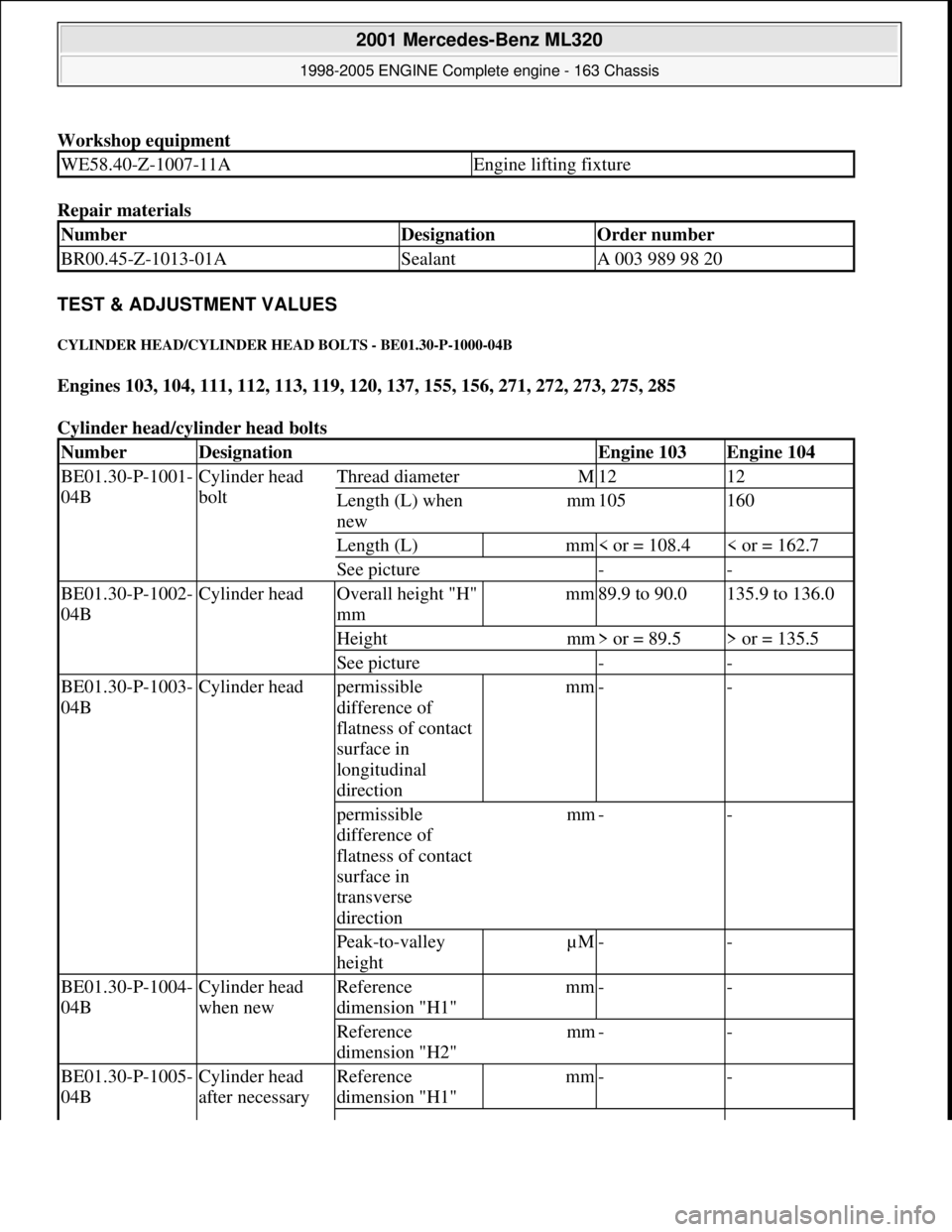
Workshop equipment
Repair materials
TEST & ADJUSTMENT VALUES
CYLINDER HEAD /CYLINDER HEAD BOLTS - BE01.30-P-1000-04B
Engines 103, 104, 111, 112, 113, 119, 120, 137, 155, 156, 271, 272, 273, 275, 285
Cylinder head/cyl inder head bolts
WE58.40-Z-1007-11AEngine lifting fixture
NumberDesignationOrder number
BR00.45-Z-1013-01ASealantA 003 989 98 20
NumberDesignationEngine 103Engine 104
BE01.30-P-1001-
04BCylinder head
boltThread diameterM1212
Length (L) when
newmm105160
Length (L)mm< or = 108.4< or = 162.7
See picture--
BE01.30-P-1002-
04BCylinder headOverall height "H"
mmmm89.9 to 90.0135.9 to 136.0
Heightmm> or = 89.5> or = 135.5
See picture--
BE01.30-P-1003-
04BCylinder headpermissible
difference of
flatness of contact
surface in
longitudinal
directionmm--
permissible
difference of
flatness of contact
surface in
transverse
directionmm--
Peak-to-valley
heightµM--
BE01.30-P-1004-
04BCylinder head
when newReference
dimension "H1"mm--
Reference
dimension "H2"mm--
BE01.30-P-1005-
04BCylinder head
after necessary Reference
dimension "H1"mm--
2001 Mercedes-Benz ML320
1998-2005 ENGINE Complete engine - 163 Chassis
me
Saturday, October 02, 2010 3:17:58 PMPage 140 © 2006 Mitchell Repair Information Company, LLC.
Page 3186 of 4133
AP82.10-P-8260GH
Check and correct headlamp adjustment
2.7.97
MODEL
163
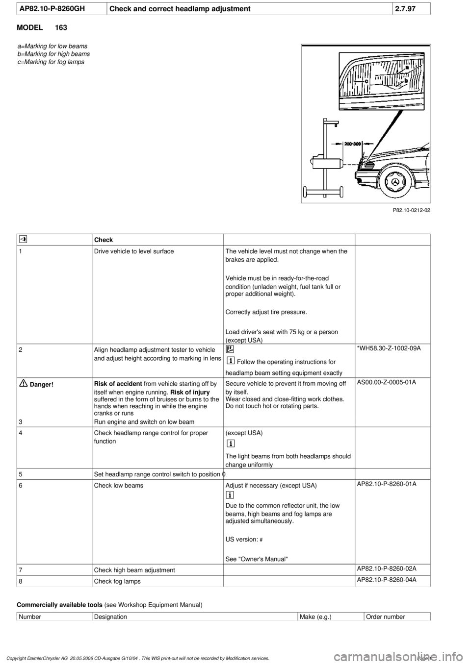
a=Marking for low beams
b=Marking for high beams
c=Marking for fog lamps
P82.10-0212-02
Check
1
Drive vehicle to level surface
The vehicle level must not change when the
brakes are applied.
Vehicle must be in ready-for-the-road
condition (unladen weight, fuel tank full or
proper additional weight).
Correctly adjust tire pressure.
Load driver's seat with 75 kg or a person
(except USA)
2
Align headlamp adjustment tester to vehicle
and adjust height according to marking in lens
Follow the operating instructions for
headlamp beam setting equipment exactly
*WH58.30-Z-1002-09A
Danger!
Risk of accident
from vehicle starting off by
itself when engine running.
Risk of injury
suffered in the form of bruises or burns to the
hands when reaching in while the engine
cranks or runs
Secure vehicle to prevent it from moving off
by itself.
Wear closed and close-fitting work clothes.
Do not touch hot or rotating parts.
AS00.00-Z-0005-01A
3
Run engine and switch on low beam
4
Check headlamp range control for proper
function
(except USA)
The light beams from both headlamps should
change uniformly
5
Set headlamp range control switch to position 0
6
Check low beams
Adjust if necessary (except USA)
AP82.10-P-8260-01A
Due to the common reflector unit, the low
beams, high beams and fog lamps are
adjusted simultaneously.
US version:
#
See "Owner's Manual"
7
Check high beam adjustment
AP82.10-P-8260-02A
8
Check fog lamps
AP82.10-P-8260-04A
Commercially available tools
(see Workshop Equipment Manual)
Number
Designation
Make (e.g.)
Order number
Copyright DaimlerChrysler AG 20.05.2006 CD-Ausgabe G/10/04 . This WIS print-out will not be recorde
d by Modification services.
Page 1
Page 3193 of 4133
AR88.40-P-3020GH
Adjust engine hood
8.4.99
MODEL
163.113 /128 /136 /154 /157 /172 /174 /175
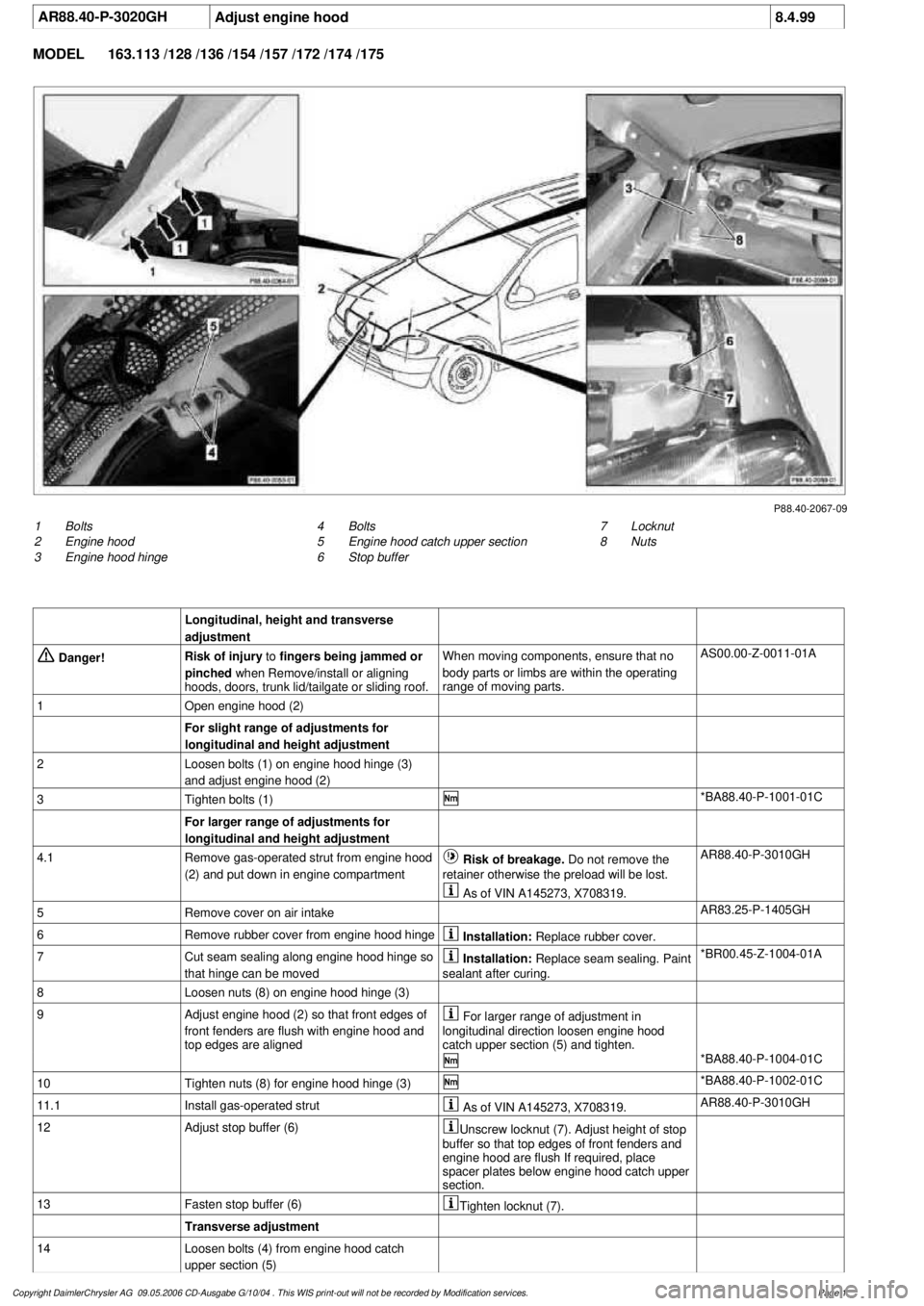
P88.40-2067-09
1
Bolts
2
Engine hood
3
Engine hood hinge
7
Locknut
8
Nuts
4
Bolts
5
Engine hood catch upper section
6
Stop buffer
Longitudinal, height and transverse
adjustment
Danger!
Risk of injury
to
fingers being jammed or
pinched
when Remove/install or aligning
hoods, doors, trunk lid/tailgate or sliding roof.
When moving components, ensure that no
body parts or limbs are within the operating
range of moving parts.
AS00.00-Z-0011-01A
1
Open engine hood (2)
For slight range of adjustments for
longitudinal and height adjustment
2
Loosen bolts (1) on engine hood hinge (3)
and adjust engine hood (2)
3
Tighten bolts (1)
*BA88.40-P-1001-01C
For larger range of adjustments for
longitudinal and height adjustment
4.1
Remove gas-operated strut from engine hood
(2) and put down in engine compartment
Risk of breakage. Do not remove the
retainer otherwise the preload will be lost.
AR88.40-P-3010GH
As of VIN A145273, X708319.
5
Remove cover on air intake
AR83.25-P-1405GH
6
Remove rubber cover from engine hood hinge
Installation:
Replace rubber cover.
7
Cut seam sealing along engine hood hinge so
that hinge can be moved
Installation:
Replace seam sealing. Paint
sealant after curing.
*BR00.45-Z-1004-01A
8
Loosen nuts (8) on engine hood hinge (3)
9
Adjust engine hood (2) so that front edges of
front fenders are flush with engine hood and
top edges are aligned
For larger range of adjustment in
longitudinal direction loosen engine hood
catch upper section (5) and tighten.
*BA88.40-P-1004-01C
10
Tighten nuts (8) for engine hood hinge (3)
*BA88.40-P-1002-01C
11.1
Install gas-operated strut
As of VIN A145273, X708319.
AR88.40-P-3010GH
12
Adjust stop buffer (6)
Unscrew locknut (7). Adjust height of stop
buffer so that top edges of front fenders and
engine hood are flush If required, place
spacer plates below engine hood catch upper
section.
13
Fasten stop buffer (6)
Tighten locknut (7).
Transverse adjustment
14
Loosen bolts (4) from engine hood catch
upper section (5)
Copyright DaimlerChrysler AG 09.05.2006 CD-Ausgabe G/10/04 . This WIS print-out will not be recorde
d by Modification services.
Page 1
Page 3195 of 4133
AR88.40-P-3020GH
Adjust engine hood
8.4.99
MODEL
163.113 /128 /136 /154 /157 /172 /174 /175
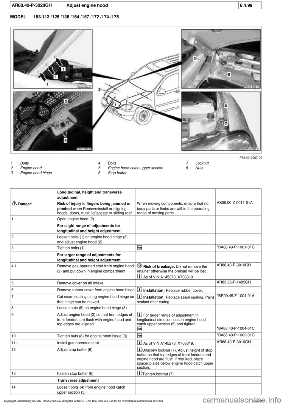
P88.40-2067-09
1
Bolts
2
Engine hood
3
Engine hood hinge
7
Locknut
8
Nuts
4
Bolts
5
Engine hood catch upper section
6
Stop buffer
Longitudinal, height and transverse
adjustment
Danger!
Risk of injury
to
fingers being jammed or
pinched
when Remove/install or aligning
hoods, doors, trunk lid/tailgate or sliding roof.
When moving components, ensure that no
body parts or limbs are within the operating
range of moving parts.
AS00.00-Z-0011-01A
1
Open engine hood (2)
For slight range of adjustments for
longitudinal and height adjustment
2
Loosen bolts (1) on engine hood hinge (3)
and adjust engine hood (2)
3
Tighten bolts (1)
*BA88.40-P-1001-01C
For larger range of adjustments for
longitudinal and height adjustment
4.1
Remove gas-operated strut from engine hood
(2) and put down in engine compartment
Risk of breakage. Do not remove the
retainer otherwise the preload will be lost.
AR88.40-P-3010GH
As of VIN A145273, X708319.
5
Remove cover on air intake
AR83.25-P-1405GH
6
Remove rubber cover from engine hood hinge
Installation:
Replace rubber cover.
7
Cut seam sealing along engine hood hinge so
that hinge can be moved
Installation:
Replace seam sealing. Paint
sealant after curing.
*BR00.45-Z-1004-01A
8
Loosen nuts (8) on engine hood hinge (3)
9
Adjust engine hood (2) so that front edges of
front fenders are flush with engine hood and
top edges are aligned
For larger range of adjustment in
longitudinal direction loosen engine hood
catch upper section (5) and tighten.
*BA88.40-P-1004-01C
10
Tighten nuts (8) for engine hood hinge (3)
*BA88.40-P-1002-01C
11.1
Install gas-operated strut
As of VIN A145273, X708319.
AR88.40-P-3010GH
12
Adjust stop buffer (6)
Unscrew locknut (7). Adjust height of stop
buffer so that top edges of front fenders and
engine hood are flush If required, place
spacer plates below engine hood catch upper
section.
13
Fasten stop buffer (6)
Tighten locknut (7).
Transverse adjustment
14
Loosen bolts (4) from engine hood catch
upper section (5)
Copyright DaimlerChrysler AG 09.05.2006 CD-Ausgabe G/10/04 . This WIS print-out will not be recorde
d by Modification services.
Page 1
Page 3510 of 4133
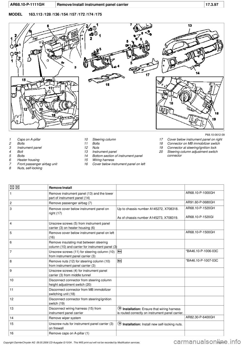
AR68.10-P-1111GH
Remove/install instrument panel carrier
17.3.97
MODEL
163.113 /128 /136 /154 /157 /172 /174 /175
P68.10-0612-09
1
Caps on A-pillar
2
Bolts
3
Instrument panel
4
Bolt
5
Bolts
6
Heater housing
7
Front passenger airbag unit
8
Nuts, self-locking
17
Cover below instrument panel on right
18
Connector on MB immobilizer switch
19
Connector at steering/ignition lock
20
Steering column adjustment switch
connector
10
Steering column
11
Bolts
12
Nuts
13
Instrument panel
14
Bottom section of instrument panel
15
Wiring harness
16
Cover below instrument panel on left
Remove/install
1
Remove instrument panel (13) and the lower
part of instrument panel (14)
AR68.10-P-1000GH
2
Remove passenger airbag (7)
AR91.60-P-0680GH
3
Remove cover below instrument panel on
right (17)
Up to chassis number A145272, X708318.
AR68.10-P-1520GH
As of chassis number A145273, X708319.
AR68.10-P-1520GI
4
Unscrew screws (5) from instrument panel
carrier (3) on heater housing (6)
5
Remove cover below instrument panel on left
(16)
AR68.10-P-1500GH
6
Remove insulating mat between steering
column (10) and carrier for instrument panel (3)
7
Unscrew screws (11) for steering column (10)
from instrument panel carrier (3)
*BA46.10-P-1006-03C
8
Remove nuts (12) for steering column (10)
from instrument panel carrier (3)
*BA46.10-P-1007-03C
9
Unscrew screws (4) for instrument panel
carrier (3) from middle tunnel
10
Disconnect connector from steering column
height adjustment switch (20)
11
Disconnect connector from MB immobilizer
switching unit (18)
12
Disconnect connector from steering/ignition
switch (19)
13
Disconnect wiring harness (15) from
instrument panel carrier
Installation:
Ensure that wiring harness
is routed correctly on instrument panel carrier.
14
Remove wiper system
AR82.30-P-6400GH
15
Unscrew nuts for instrument panel carrier (3)
on firewall
Installation:
Install new self-locking nuts.
16
Remove caps on A-pillar (1)
Copyright DaimlerChrysler AG 09.05.2006 CD-Ausgabe G/10/04 . This WIS print-out will not be recorde
d by Modification services.
Page 1
Page 3542 of 4133

Jacket tube
REMOVING AND INSTALLING CENTER AIR NOZZLE - AR68.10-P-1150GH
MODEL 163.113 /128 /136 /154 /157 /172 /174 /175
panel (3)
7Unscrew screws (11) for steering column
(10) from instrument panel carrier (3) *BA46.10-P-
1006-03C
8Remove nuts (12) for steering column (10)
from instrument panel carrier (3) *BA46.10-P-
1007-03C
9Unscrew screws (4) for instrument panel
carrier (3) from middle tunnel
10Disconnect connector from steering column
height adjustment switch (20)
11Disconnect connector from MB
immobilizer switching unit (18)
12Disconnect connector from steering/ignition
switch (19)
13Disconnect wiring harness (15) from
instrument panel carrier Installation:Ensure that wiring
harness is routed correctly on
instrument panel carrier.
14Remove wiper system AR82.30-P-
6400GH
15Unscrew nuts for instrument panel carrier
(3) on firewall Installation: Install new self-
locking nuts.
16Remove caps on A-pillar (1)
17Unscrew screws (2) for instrument panel
carrier (3) from A-pillar
18
Remove instrument panel carrier (3) and
take out of passenger compartment to side
through passenger doorBe careful not to damage center
console when removing and
installing.
19Install in the reverse order
NumberDesignationMODEL Series
163
BA46.10-P-1006-
03CScrew for jacket tube on upper instrument panel carrierNm20
BA46.10-P-1007-
03CJacket tube collar nut on instrument panel carrier at
bottomNm18
2001 Mercedes-Benz ML320
1998-2005 ACCESSORIES & BODY, CAB Interior Equipment - 163 Chassis
me
Saturday, October 02, 2010 3:35:21 PMPage 24 © 2006 Mitchell Repair Information Company, LLC.
Page 3789 of 4133
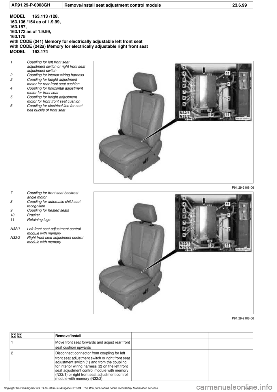
AR91.29-P-0008GH
Remove/install seat adjustment control module
23.6.99
MODEL
163.113 /128,
163.136 /154 as of 1.9.99,
163.157,
163.172 as of 1.9.99,
163.175
with CODE (241) Memory for electrically adjustable left front seat
with CODE (242a) Memory for electrically adjustable right front seat
MODEL
163.174
P91.29-2108-06
1
Coupling for left front seat
adjustment switch or right front seat
adjustment switch
2
Coupling for interior wiring harness
3
Coupling for height adjustment
motor for rear front seat cushion
4
Coupling for horizontal adjustment
motor for front seat
5
Coupling for height adjustment
motor for front front seat cushion
6
Coupling for electrical line for seat
belt buckle of front seat
P91.29-2108-06
7
Coupling for front seat backrest
angle motor
8
Coupling for automatic child seat
recognition
9
Coupling for heated seats
10
Bracket
11
Retaining lugs
N32/1
Left front seat adjustment control
module with memory
N32/2
Right front seat adjustment control
module with memory
Remove/Install
1
Move front seat forwards and adjust rear front
seat cushion upwards
2
Disconnect connector from coupling for left
front seat adjustment switch or right front seat
adjustment switch (1) and from the coupling
for interior wiring harness (2) on the left front
seat adjustment control module with memory
(N32/1) or right front seat adjustment control
module with memory (N32/2)
Copyright DaimlerChrysler AG 14.06.2006 CD-Ausgabe G/10/04 . This WIS print-out will not be recorde
d by Modification services.
Page 1
Page 3798 of 4133
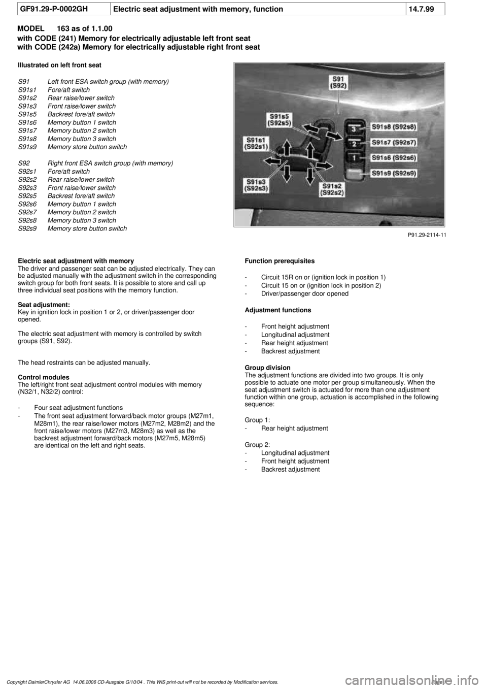
GF91.29-P-0002GH
Electric seat adjustment with memory, function
14.7.99
MODEL
163 as of 1.1.00
with CODE (241) Memory for electrically adjustable left front seat
with CODE (242a) Memory for electrically adjustable right front seat
P91.29-2114-11
Illustrated on left front seat
S91
Left front ESA switch group (with memory)
S91s1
Fore/aft switch
S91s2
Rear raise/lower switch
S91s3
Front raise/lower switch
S91s5
Backrest fore/aft switch
S91s6
Memory button 1 switch
S91s7
Memory button 2 switch
S91s8
Memory button 3 switch
S91s9
Memory store button switch
S92
Right front ESA switch group (with memory)
S92s1
Fore/aft switch
S92s2
Rear raise/lower switch
S92s3
Front raise/lower switch
S92s5
Backrest fore/aft switch
S92s6
Memory button 1 switch
S92s7
Memory button 2 switch
S92s8
Memory button 3 switch
S92s9
Memory store button switch
Electric seat adjustment with memory
The driver and passenger seat can be adjusted electrically. They can
be adjusted manually with the adjustment switch in the corresponding
switch group for both front seats. It is possible to store and call up
three individual seat positions with the memory function.
Seat adjustment:
Key in ignition lock in position 1 or 2, or driver/passenger door
opened.
The electric seat adjustment with memory is controlled by switch
groups (S91, S92).
The head restraints can be adjusted manually.
Control modules
The left/right front seat adjustment control modules with memory
(N32/1, N32/2) control:
-
Four seat adjustment functions
-
The front seat adjustment forward/back motor groups (M27m1,
M28m1), the rear raise/lower motors (M27m2, M28m2) and the
front raise/lower motors (M27m3, M28m3) as well as the
backrest adjustment forward/back motors (M27m5, M28m5)
are identical on the left and right seats.
Function prerequisites
-
Circuit 15R on or (ignition lock in position 1)
-
Circuit 15 on or (ignition lock in position 2)
-
Driver/passenger door opened
Adjustment functions
-
Front height adjustment
-
Longitudinal adjustment
-
Rear height adjustment
-
Backrest adjustment
Group division
The adjustment functions are divided into two groups. It is only
possible to actuate one motor per group simultaneously. When the
seat adjustment switch is actuated for more than one adjustment
function within one group, actuation is accomplished in the following
sequence:
Group 1:
-
Rear height adjustment
Group 2:
-
Longitudinal adjustment
-
Front height adjustment
-
Backrest adjustment
Copyright DaimlerChrysler AG 14.06.2006 CD-Ausgabe G/10/04 . This WIS print-out will not be recorde
d by Modification services.
Page 1
Page 3801 of 4133
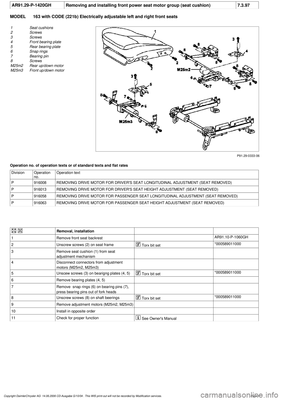
AR91.29-P-1420GH
Removing and installing front power seat motor group (seat cushion)
7.3.97
MODEL
163 with CODE (221b) Electrically adjustable left and right front seats
P91.29-0333-06
1
Seat cushions
2
Screws
3
Screws
4
Front bearing plate
5
Rear bearing plate
6
Snap rings
7
Bearing pin
8
Screws
M25m2
Rear up/down motor
M25m3
Front up/down motor
Operation no. of operation texts or of standard texts and flat rates
Division
Operation
no.
Operation text
P
916008
REMOVING DRIVE MOTOR FOR DRIVER'S SEAT LONGITUDINAL ADJUSTMENT (SEAT REMOVED)
P
916013
REMOVING DRIVE MOTOR FOR DRIVER'S SEAT HEIGHT ADJUSTMENT (SEAT REMOVED)
P
916058
REMOVING DRIVE MOTOR FOR PASSENGER SEAT LONGITUDINAL ADJUSTMENT (SEAT REMOVED)
P
916063
REMOVING DRIVE MOTOR FOR PASSENGER SEAT HEIGHT ADJUSTMENT (SEAT REMOVED)
Removal, installation
1
Remove front seat backrest
AR91.10-P-1060GH
2
Unscrew screws (2) on seat frame
Torx bit set
*000589011000
3
Remove seat cushion (1) from seat
adjustment mechanism
4
Disconnect connectors from adjustment
motors (M25m2, M25m3)
5
Unscew screws (3) on bearigng plates (4, 5)
Torx bit set
*000589011000
6
Remove bearing plates (4, 5)
7
Remove snap rings (6) on bearing pins (7),
press bearing pins out of fork heads
8
Unscrew screws (8) on shaft beerings
Torx bit set
*000589011000
9
Remove adjustment motors (M25m2, M25m3)
10
Install in opposite order
11
Check for proper function
See Owner's Manual
Copyright DaimlerChrysler AG 14.06.2006 CD-Ausgabe G/10/04 . This WIS print-out will not be recorde
d by Modification services.
Page 1
Page 3803 of 4133
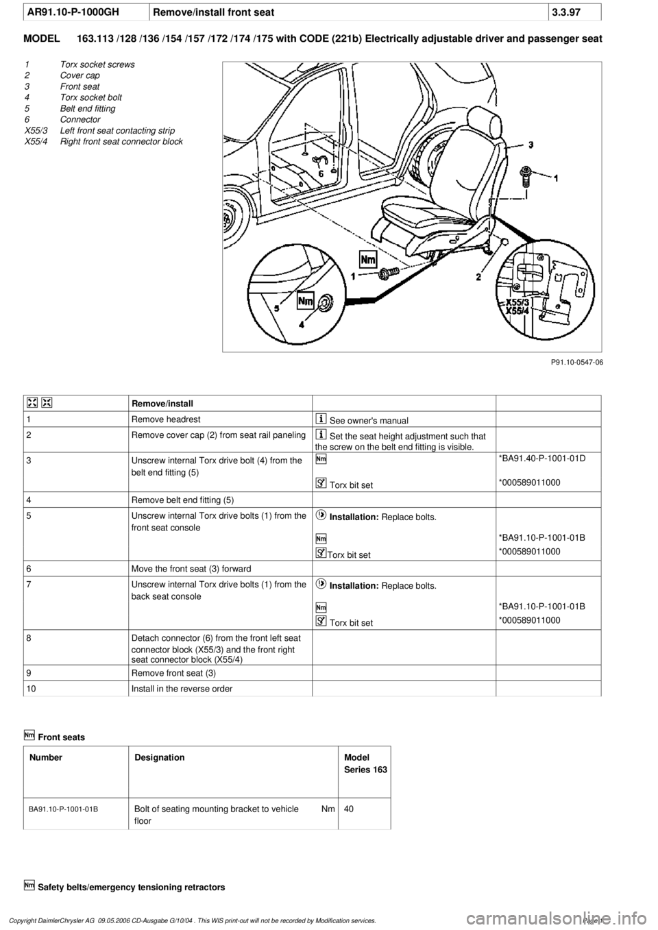
AR91.10-P-1000GH
Remove/install front seat
3.3.97
MODEL
163.113 /128 /136 /154 /157 /172 /174 /175 with CODE (221b) Electrically adjustable driver and passe
nger seat
P91.10-0547-06
1
Torx socket screws
2
Cover cap
3
Front seat
4
Torx socket bolt
5
Belt end fitting
6
Connector
X55/3
Left front seat contacting strip
X55/4
Right front seat connector block
Remove/install
1
Remove headrest
See owner's manual
2
Remove cover cap (2) from seat rail paneling
Set the seat height adjustment such that
the screw on the belt end fitting is visible.
3
Unscrew internal Torx drive bolt (4) from the
belt end fitting (5)
*BA91.40-P-1001-01D
Torx bit set
*000589011000
4
Remove belt end fitting (5)
5
Unscrew internal Torx drive bolts (1) from the
front seat console
Installation:
Replace bolts.
*BA91.10-P-1001-01B
Torx bit set
*000589011000
6
Move the front seat (3) forward
7
Unscrew internal Torx drive bolts (1) from the
back seat console
Installation:
Replace bolts.
*BA91.10-P-1001-01B
Torx bit set
*000589011000
8
Detach connector (6) from the front left seat
connector block (X55/3) and the front right
seat connector block (X55/4)
9
Remove front seat (3)
10
Install in the reverse order
Front seats
Number
Designation
Model
Series 163
BA91.10-P-1001-01BBolt of seating mounting bracket to vehicle
floor
Nm
40
Safety belts/emergency tensioning retractors
Copyright DaimlerChrysler AG 09.05.2006 CD-Ausgabe G/10/04 . This WIS print-out will not be recorde
d by Modification services.
Page 1